Sign In
Upload
Download
Table of Contents
Contents
Add to my manuals
Delete from my manuals
Share
URL of this page:
HTML Link:
Bookmark this page
Add
Manual will be automatically added to "My Manuals"
Print this page
×
Bookmark added
×
Added to my manuals
Manuals
Brands
Dru Manuals
Indoor Fireplace
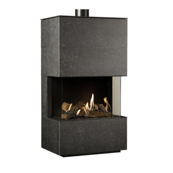
Lugo 70
Installation manual
Dru Lugo 70 Installation Manual
G20/g25/g25.3 natural gas
Hide thumbs
1
Table Of Contents
2
3
4
5
6
7
8
9
10
11
12
13
14
15
16
17
18
19
20
21
22
23
24
25
26
27
28
29
30
31
32
33
34
35
36
37
38
39
40
41
42
43
44
page
of
44
Go
/
44
Contents
Table of Contents
Bookmarks
Table of Contents
Table of Contents
1 Introduction
2 CE Declaration
3 Safety
General
Regulations
Precautions / Safety Instructions at Installation
Principle of Ignition Cycle
4 Removing the Packaging
5 Installation
Type of Gas
Gas Connection
Electric Connection
Placing the Appliance
Placing a Built-In Appliance
Placing the Chimney Breast
Placing the Control Hatch
Connection to Existing Chimney
Placing Concentric System
Additional Instructions
Suspended Placement of Appliance
Platform
Mantel Iron
Glass Panes
Setting the Appliance
Wood Set
6 Control
Remote Controls
Alternative Controls
7 Final Inspection
Gastightness
Gas Pressure/Line-Pressure
Ignition Main Burner
Flame Picture
8 Maintenance
Parts
9 Delivery
10 Malfunctions
Appendix 1 Malfunctions
Error Messages
Appendix 2 Tables
Appendix 3 Figures
Advertisement
Quick Links
1
Remote Controls
2
Appendix 3 Figures
Download this manual
Lugo 70
Lugo 80
G20/G25/G25.3 Natural gas
Installation manual (UK/IE)
Store this document in a safe place
UK
Table of
Contents
Previous
Page
Next
Page
1
2
3
4
5
Advertisement
Table of Contents
Need help?
Do you have a question about the Lugo 70 and is the answer not in the manual?
Ask a question
Questions and answers
Related Manuals for Dru Lugo 70
Indoor Fireplace Dru Lugo 80 Installation Manual
G20/g25/g25.3 natural gas (44 pages)
Indoor Fireplace Dru Largo Tunnel Instructions For Installation Manual
Decorative gas heating appliance (24 pages)
Indoor Fireplace Dru G25 Installation Manual
(36 pages)
Indoor Fireplace Dru Lugo 70 RCH Installation Manual
(44 pages)
Indoor Fireplace Dru Lugo 80 RCH Instruction Manual
(44 pages)
Indoor Fireplace Dru Romano Installation And Operation Instructions Manual
Dru romano natural gas fire instructions for installation and operations (19 pages)
Indoor Fireplace Dru Apollo 100 Instructions For Installation Manual
Version with a set of logs (60 pages)
Indoor Fireplace Dru Metro 130 Tunnel Instructions For Installation Manual
Decorative gas heating appliance (28 pages)
Indoor Fireplace Dru Trio G20 Instructions For Installation Manual
Freestanding atmospheric gas heating appliance (20 pages)
Indoor Fireplace Dru Metro 100 XT Tunnel Instructions For Installation Manual
(28 pages)
Indoor Fireplace Dru Spirit Instructions For Installation And Operation Manual
(20 pages)
Indoor Fireplace Dru Metro 100 XT-3 Installation Manual
Atmospheric gas-fired heating appliance (52 pages)
Indoor Fireplace Dru DIABLO Instructions For Installation And Operation Manual
(40 pages)
Indoor Fireplace Dru DIABLO (PROPAAN) Instructions For Installation And Operation Manual
(32 pages)
Indoor Fireplace Dru G25 Installation Manual
Diablo natural gas indoor fireplace (36 pages)
Indoor Fireplace Dru CONCERTO CF Installation And Operation Manual
(40 pages)
This manual is also suitable for:
Lugo 80
Table of Contents
Print
Rename the bookmark
Delete bookmark?
Delete from my manuals?
Login
Sign In
OR
Sign in with Facebook
Sign in with Google
Upload manual
Upload from disk
Upload from URL


Need help?
Do you have a question about the Lugo 70 and is the answer not in the manual?
Questions and answers