Table of Contents
Advertisement
Quick Links
Download this manual
See also:
Installation Manual
Advertisement
Table of Contents

Related Manuals for Dru Largo Tunnel


Summary of Contents for Dru Largo Tunnel
- Page 1 Largo - Largo Tunnel Instructions for installation (GB / IE) Please retain this document carefully...
-
Page 2: Table Of Contents
Spare parts Foreword As manufacturer of gas heating appliances, DRU develops and produces products to meet the highest possible quality, performance and safety requirements. As a result of which the user is able to enjoy using your appliance for years to come. -
Page 3: Introduction
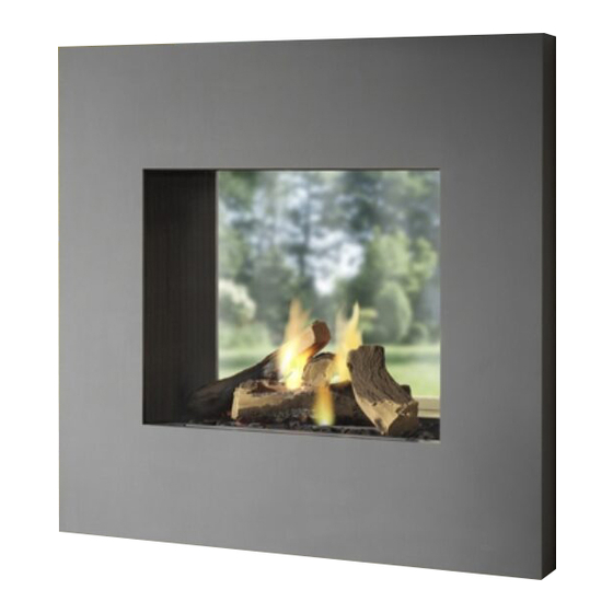
The appliance is available in two models, the Largo and the Largo Tunnel. The Largo is a ‘standard’ gas fi re and should always be installed against a wall. The Largo Tunnel is just that, a ‘tunnel fi re’ with both a front and back window. -
Page 4: Instructions
Annex 1 / Table 4 specifi es the components you should have once everything has been unpacked. ➠ Contact DRU Service if after unpacking the appliance you do not have all the components; ➠ Dispose of the packaging in an appropriate manner. -
Page 5: Positioning The Appliance
- Allow for the depth of the appliance (see Fig. 2 (Largo: minimum of 450 mm; Largo Tunnel: minimum of 470 mm); - Allow for the build-in height; this will depend on the height of the adjustable feet (see Fig. 1 ➠... -
Page 6: Flue Gas Discharge / Combustion Air Supply System
If necessary, you can also use an existing discharge channel (see section 6.5.4). N.B. - Only use the concentric system supplied by DRU (Ø100 / Ø150 mm). This system was tested in com- bination with the appliance; DRU cannot guarantee Fig. - Page 7 A R G O I N S T R U C T I O N F O R I N S TA L L AT I O N 6.5.2.2 Installing the concentric system To install the concentric system commence as follows: ➠...
- Page 8 L A R G O I N S T R U C T I O N F O R I N S TA L L AT I O N Examples To clarify, we will give 2 examples to determine the allowability of a concentric system and the conditions for setting the appliance.
-
Page 9: Building The Chimney Breast
- protecting the gas control block and hoses from cement and plaster. !Tip The vents should preferably be created in both sides of the chimney breast: you could use DRU ventilation elements. ➠ Check that the concentric system has been installed correctly;... -
Page 10: Installing The Control Box
L A R G O I N S T R U C T I O N F O R I N S TA L L AT I O N 6.7 Installing the control box The control box is to be installed as low as possible. The control box contains various components such as the type plate, the gas control block, and the receiver for the remote control. - Page 11 A R G O I N S T R U C T I O N F O R I N S TA L L AT I O N 6.8.2 Air inlet guides The air inlet guides are located at the bottom (side) of the tray surrounding the burners (see Fig.
- Page 12 L A R G O I N S T R U C T I O N F O R I N S TA L L AT I O N Photo 4 Photo 5 Photo 6...
-
Page 13: Arranging The Logs
A R G O I N S T R U C T I O N F O R I N S TA L L AT I O N Photo 7 Photo 8 6.9 Arranging the logs The appliance is supplied with a set of logs. The log set consists of vermiculite (see Photo 2), chippings (see... -
Page 14: Glass Window
L A R G O I N S T R U C T I O N F O R I N S TA L L AT I O N !Tip The burn marks on the logs will help you identify them. ➠... - Page 15 A R G O I N S T R U C T I O N F O R I N S TA L L AT I O N Photo 9a Photo 12a Photo 12b Photo 9b Photo 12c Photo 12d Photo 10 Photo 11 Photo 12e...
-
Page 16: Wireless Remote Control
L A R G O I N S T R U C T I O N F O R I N S TA L L AT I O N Photo 13 Photo 14 Wireless remote control See Chapter 4 of the User Manual, ‘Remote Control’, for details of how to operate the system. The remote system consists of a remote control system and a receiver. -
Page 17: Final Inspection
A R G O I N S T R U C T I O N F O R I N S TA L L AT I O N Photo 15 Photo 16 Final inspection To ensure the appliance is working correctly and safely, check the following before use: 8.1 Gastightness N.B. -
Page 18: Flame Effect
L A R G O I N S T R U C T I O N F O R I N S TA L L AT I O N If the main burner does not ignite, then: ➠ Check that button A on the gas control block is set to ON; ➠... -
Page 19: Troubleshooting
A R G O I N S T R U C T I O N F O R I N S TA L L AT I O N 11. Troubleshooting A number of faults which could occur, their possible causes and solutions are shown in the table below: Table 3: Troubleshooting Problem Possible cause... - Page 20 L A R G O I N S T R U C T I O N F O R I N S TA L L AT I O N G. Pilot burner is burning but 1. Thermocouple is not working 1.1 Measure the voltage with a digital multi- the magnetic valve closes meter, set to mV range, by connecting the...
-
Page 21: Annex 1 Components Supplied
Penlight battery (AA type) 923100 Pressure coupling 15 mm x G3/8” 149234 Annex 2 Technical data The technical data for the Largo/ Largo Tunnel are given in the table below. Table 5: Technical data Type C11/C31 Gas type Burner pressure... - Page 22 L A R G O Notes ........................................... . .
- Page 23 L A R G O Notes ........................................... . .
- Page 24 DRU Verwarming B.V. The Netherlands Postbus 1021, NL-6920 BA Duiven Ratio 8, NL-6921 RW Duiven...
Need help?
Do you have a question about the Largo Tunnel and is the answer not in the manual?
Questions and answers