Table of Contents
Advertisement
Quick Links
IMPORTANT:
THESE INSTRUCTIONS ARE TO
REMAIN WITH THE
HOMEOWNER
FOR YOUR SAFETY
WARNING:
If the information in this
manual is not followed exactly, a fi re or
explosion may result causing property
damage, personal injury or loss of life.
-- Do not store or use gasoline or other
fl ammable vapours and liquids in the
vicinity of this or any other appliance.
-- WHAT TO DO IF YOU SMELL GAS
• Do not try to light any appliance.
• Do not touch any electrical switch; do
not use any phone in your building.
• Immediately call your gas supplier
from a neighbour's phone. Follow
the gas supplier's instructions.
• If you cannot reach your gas supplier,
call the fi re department.
--Installation and service must be performed
by a qualifi ed installer, service agency or
the gas supplier.
This appliance may be installed in an
aftermarket permanently located, manu-
factured home (USA only) or mobile home,
where not prohibited by local codes.
This appliance is only for use with the
type of gas indicated on the rating plate.
This appliance is not convertible for use
with other gases, unless a certifi ed kit is
used.
050505-36
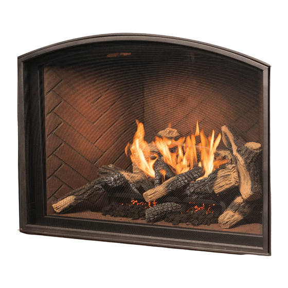
TC36 AR
DIRECT VENT FIREPLACE
INSTALLATION
AND OPERATING
INSTRUCTIONS
36ARB2
MODEL
SERIES B
MODULAR
5056.428091
Advertisement
Table of Contents

Related Manuals for Town & Country Fireplaces TC36 AR


Summary of Contents for Town & Country Fireplaces TC36 AR
- Page 1 MODEL This appliance may be installed in an aftermarket permanently located, manu- TC36 AR factured home (USA only) or mobile home, SERIES B where not prohibited by local codes. MODULAR...
-
Page 2: Table Of Contents
Contents CAUTION ......................3 SAFETY ........................ 3 INSTALLATION REQUIREMENTS ............... 5 TOP STANDOFFS ....................5 LOCATING THE FIREPLACE ................5 FRAMING AND FINISHING .................. 6 HEARTH EXTENSION ..................8 CONTROL BOX ....................8 VENTING ......................10 WALL TERMINATION VENTING ................ 10 ROOF TERMINATION VENTING ............... -
Page 3: Caution
CAUTION SAFETY FOR YOUR SAFETY - Do not install or operate your Town Due to high temperatures, this gas appliance should and Country fi replace without fi rst reading and understanding be located out of traffi c and away from furniture and this manual. - Page 4 Fig. # 2 COMBUSTIBLE FRAMING AND FINISH WALL ABOVE STANDOFFS STEEL FRAMING MAY USE COMBUSTIBLE FACING MATERIAL IN THIS AREA STANDOFFS NON-COMBUSTIBLE NON-COMBUSTIBLE ZONE. FINISH MATERIAL DO NOT INSTALL ANY SEE FIG #7 COMBUSTIBLE MATERIAL, ELECTRICAL WIRING OR GAS PLUMBING IN THIS AREA.
-
Page 5: Installation Requirements
INSTALLATION REQUIREMENTS TOP STANDOFFS The Town & Country Fireplace installation and venting The top standoffs are shipped loose inside the fi replace and must conform to the current CAN/CGA-B149 installation must be installed on top of the fi replace as shown in fi g. #4. code (in Canada) or the current National Fuel Gas Code, Do this once the fi replace is on site and in position. -
Page 6: Framing And Finishing
the fi replace is in its fi nal position. Secure the steel frame to the framing brackets on each side of the unit. Ensure that FRAMING AND FINISHING the studs are set back far enough to allow for thickness of fi nishing surface. - Page 7 Fig. # 8 NON-COMBUSTIBLE RECESSED CONCRETE BOARD Fig. # 7 INSTALLATION DETAIL DETAIL CONCRETE BOARD NON-COMBUSTIBLE CONCRETE MASONRY TYPE BOARD MATERIAL STEEL STUDS 6" Concrete board (or other non- combustible material) must extend 12" above and 4 1/2" to the sides of the framing edges.
-
Page 8: Hearth Extension
CONTROL BOX Fig. # 10 MANUAL MILLIVOLT VALVE CONTROL The gas control system is housed in a control box remote of PILOT DOOR AND the fi replace. Flexible conduits attach the control box to the FLAME BATTERY SPARK FRAME fi replace and house all the plumbing and wiring to the burner. INDICATOR IGNITER This unique design allows the control box to be mounted in... - Page 9 CONTROL BOX LOCATION AND Fig. # 12 FRAMING DETAIL 4 1/4" CAUTION: - A 2 foot service access clearance is recom- 12" mended in front of the control box. - If recessed into a masonry wall, allow for control door and frame removal. - If fl ush mounted on a masonry wall, allow for conduit to exit out the bottom of control box.
-
Page 10: Venting
VENTING WALL TERMINATION VENTING Before installing venting for this unit, the installer should read Exterior wall opening: these instructions to insure that the proper vent confi guration Determine the exact position of the fi replace so that the vent has been selected. pipe is centred (if possible) between two building framing Use only Town and Country Termination kits #: members. - Page 11 Fig. # 14 WALL THIMBLE AND VENT MUST NOT PROTRUDE BEYOND SIDING Wall thimble: Where a vent pipe passes through a combustible wall, a wall thimble/shield must be used to retain insulation and maintain proper clearances. The wall thimble may be cut to length for various wall thicknesses up to 12"...
- Page 12 Vent pipe: Wall vent terminal: Install vent pipe through the wall thimble and attach to fl ue 1) Engage the 8" vent collar with the vent pipe and slide outlet collar on top of the fi replace. Secure all joints with screws terminal into place.
- Page 13 WALL TERMINATION Fig. # 17 VENTING CHART Pipe length Minimum rise Pipe length Maximum run Maximum 68 1/2” 24” 18" 74 1/2” 30” 76" 80 1/2” 36” 11' 2 1/8" 86 1/2” 42” 92 1/2” 48” 20’ 10 1/4” For other rise/run combinations see chart below 24"...
- Page 14 ROOF TERMINATION Fig. # 18 VENTING CHART Pipe length Minimum rise Pipe length Maximum run Maximum 68 1/2” 24” 26 5/16" 74 1/2” 30” 84 3/8" 80 1/2” 36” 11' 10 1/2" 86 1/2” 42” 16' 8 1/2" 92 1/2” 48”...
-
Page 15: Roof Termination Venting
ROOF TERMINATION VENTING Fig. # 20 Ceiling opening: 1) Determine the exact position of the fi replace so that the 14 1/2" vent pipe is centered (if possible) between two building framing members. Lay out the vent system path, minimiz- ing the number of elbows and length of vent. - Page 16 Roof vent terminal: 1) Place the roof fl ashing over top of the vent pipe and nail securely to the roof using roofi ng nails, top and sides UNDER shingles, lower end OVER shingles to provide a watershed. Make weather tight by sealing with a roofi ng compound (see Fig.
-
Page 17: Vent Terminal Clearance
VENT TERMINAL VENT TERMINAL MINIMUM Fig. # 22a CLEARANCE CLEARANCES TO ADJACENT STRUCTURES Minimum clearances to the vent terminal must be maintained as shown in fi gure #22a & b. Measure clearances to the nearest edge of termination hood. 36" (91.5 cm) 24"... -
Page 18: Insulated Collar Shield
VENT PIPE SEALANT Fig. #23 APPROVED "HIGH TEMP." SELF-ADHESIVE ALUMINUM TAPE VENT PIPE INSULATED COLLAR SHIELD MUST (Included) BE USED. SEE SECTION BELOW VENT PIPE SEALANT Fig. #24 INSULATION All outer joints of the vent pipe must be sealed with the ap- COVER (2 pcs.) proved "High Temp."... -
Page 19: Vent Restrictor Adjustment
VENT RESTRICTOR ADJUSTMENT Fig. # 26 WALL AND ROOF The vent restrictor is located on the underside of the fi rebox TERMINATION top. The unit leaves the factory with the vent restrictor wide open. The restrictor is built into the appliance for secondary RESTRICTOR air fl ow adjustment. -
Page 20: Gas Supply
GAS SUPPLY Caution: The gas line should be installed by a qualifi ed service person in accordance with all building codes. This Recommended Thermostat Wire Size section is intended as a guide for qualifi ed technicians installing this appliance. Consult local and/or national Wire Size Max. -
Page 21: Window Frame Removal
WINDOW FRAME REMOVAL Fig # 29 UPPER FIREBOX SHIELD Warning: Turn off the fi replace, and allow ample time for the unit to cool before proceeding. Caution: The ceramic glass is very fragile, and should be handled with care. The window frame is held in place by two spring-loaded latches and are operated by a removable handle. -
Page 22: Firebox Panels Installation
FIREBOX PANELS INSTALLATION Fig. #32 ADJUSTABLE "V" BRACKET (HERRINGBONE ....TCPN.7566) (TUSCAN ........ TCPN.748) (HERITAGE RED ....TCPN.75704) For porcelin panel kit (TCPN.75702) installation see in- structions provided with panel kit. The Firebox Panels have to be installed for safe operation. Do not use the fi replace without panels. -
Page 23: First Fire
LIGHTING INSTRUCTIONS - Millivolt Valve FOR YOUR SAFETY READ BEFORE LIGHTING building. - Immediately call your gas supplier from a neighbour's phone. WARNING: If you do not follow these instructions Follow the gas supplier's instructions. exactly, a fi re or explosion may result causing - If you cannot reach your gas supplier, call the fi... -
Page 24: Lighting Instructions - Electronic Valve
1) HI-LO Flame Adjustment: Electronic Valve: Push the "Burner" switch to the "Off" posi- The HI-LO burner control knob can be rotated in both direc- tion. Turn off all electric power to the appliance and remove tions, providing infi nite control of gas fl ow rate to the burner backup batteries if service is to be performed or for extended and therefore greater comfort control. -
Page 25: Maintenance
APPENDIX A Annual Inspection: MAINTENANCE a) Remove glass panel and log set. Inspect logs and burner Caution: Turn off gas and electrical power supply (if appli- assembly for soot buildup. If excessive buildup of soot is cable) and allow ample time for unit to cool before servicing present, have a qualifi ed service person inspect and adjust unit appliance. -
Page 26: Replacement Parts
REPLACEMENT PARTS (WHEN ORDERING, INCLUDE PART NUMBER WITH DESCRIPTION) ITEM DESCRIPTION PART NO. ITEM DESCRIPTION PART NO. 12..PANEL, LOWER BACK, HERNGBN ... 5098.7562 1.... GLASS FRAME ......TC36.9520WLD ....PANEL, LOWER BACK, TUSCAN ..5098.7471 2.... REPLACEMENT GLASS (c/w gasket) GLAS.2088 .... -
Page 27: Replacement Parts-Millivolt Control Assembly
REPLACEMENT PARTS-MILLIVOLT CONTROL ASSEMBLY (WHEN ORDERING, INCLUDE PART NUMBER WITH DESCRIPTION) ITEM ..DESCRIPTION ........PART NO. ITEM ..DESCRIPTION ........PART NO. 1.... KNOB, EXT, ON/OFF 1-1/2 ....5007.315 2.... KNOB, EXT, HI/LO 1-1/2 ......5007.316 20..LOWER CONTROL PANEL ASSEM. .. TC42.9071 3.... -
Page 28: Replacement Parts - Electronic Control Assembly
REPLACEMENT PARTS - ELECTRONIC CONTROL ASSEMBLY ITEM ..DESCRIPTION ........PART NO. ITEM ..DESCRIPTION ........PART NO. 1.... ELECTRONIC, VALVE, NG ...... 5030.01 2.... ELECTRONIC, IGNITION MODULE ..5030.02 10..LOWER CNTRL PNL ASSY ELEC ..TC42.90712 3.... ELECTRONIC, BATTERY HOLDER ..5030.03 11.. -
Page 29: Electronic Valve Wiring Diagram
ELECTRONIC VALVE WIRING DIAGRAM Fig. # 39 Ignition Pilot Module Assembly Note: Wire Tags Black (S) are bracketed [through Gas line conduit] Electrode Flame Sensor Black (I) [through independent conduit] Battery Pilot Black Holder Gas Line Burner Switch Gas Valve Battery Relay Wire... -
Page 30: Wall Termination Kit
Fig. # 40 WALL TERMINATION KIT TCVT.WTA WALL TERMINAL TCVT.9360 WALLSHIELD/CEILING FIRESTOP THIMBLE TCVT.THIMA WALL SHIELD/CEILING FIRESTOP THIMBLE Fig. # 41 TCVT.THIMA 36ARB2 050505-36... -
Page 31: Roof Termination Kit
Fig. # 42 ROOF TERMINATION KIT TC36.RTA VERTICAL TERMINATION CAP TCVT.9365 STORM COLLAR TC42.90665 CEILING FIRESTOP TCVT.THIMA ROOF SUPPORT BRACKET TCVT.93915 050505-36 36ARB2... -
Page 32: Vent Pipe Dimensions
Fig. # 43 VENT PIPE DIMENSIONS 11" 12" Pipe ..... 10 1/4" 18" Pipe ..... 16 1/4" 24" Pipe ..... 22 1/4" 10 15/16" 48" Pipe ..... 46 1/4" 9 1/2" TCVT.811X12ADJ 11 1/8" TCVT.811X _ _ 13 13/16" 12 9/16" 8 5/16"... -
Page 33: Vent Offset Chart
Fig. # 44 VENT OFFSET CHART 12" Pipe..18 5/8"..18" 18" Pipe..22 7/8"..22 3/8" 10 7/8" 24" Pipe..27 1/8"..26 1/2" 48" Pipe..44 1/16"..43 1/2" Adding an adjustable section 1 1/4” to pipe will increase offset by 11 3/8" 2 1/8" to 6 3/4" 1 1/4”... -
Page 34: Various Gas Supply Connections
VARIOUS GAS SUPPLY CONNECTIONS Note: Consult local codes before proceeding. Fig. # 47 GASTITE FLEX LINE WITH Fig. # 45 REDUCING COUPLING FLEXIBLE CONNECTOR WITH SHUTOFF VALVE Fig. # 48 COPPER LINE WITH FLARE FITTING Fig. # 46 BLACK IRON PIPE WITH UNION * USA ONLY Copper piping may only be used in compliance with local... -
Page 35: Safety Label Location
VENTED GAS FIREPLACE - NOT FOR USE WITH SOLID FUEL FOYER AU GAZ À ÉVACUATION - NE PAS UTILISER AVEC DU COMBUSTIBLE SOLIDE This Appliance is Equipped For Use With / ANSI Z21.50b-2002 / CSA 2.22b-2002 Vented Gas Fireplaces CAN/CGA 2.17-M91 Gas-Fired Appliance For Use At High Altitudes. Cet Appareil est Équipé... - Page 36 2975 Allenby Rd., Duncan, BC V9L 6V8 Phone: 1-888-223-0088 Web site: www.townandcountryfi replaces.net Printed in Canada...
Need help?
Do you have a question about the TC36 AR and is the answer not in the manual?
Questions and answers