
Related Manuals for Rice Lake IQ plus 2100SL


Summary of Contents for Rice Lake IQ plus 2100SL
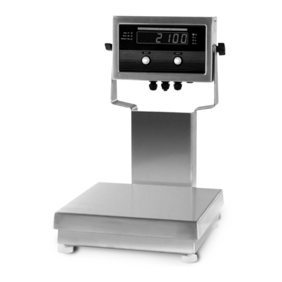
- Page 1 IQ plus 2100 ® Digital Bench Scale Version 1.02 Installation Manual To be the best by every measure 53415...
-
Page 3: Table Of Contents
Course descriptions and dates can be viewed at www.rlws.com or obtained by calling 715-234-9171 and asking for the training department. © 2003 Rice Lake Weighing Systems. All rights reserved. Printed in the United States of America. Specifications subject to change without notice. - Page 4 6.3 Enclosure Reassembly............21 6.4 Board Removal .
-
Page 5: About This Manual
Revolution configuration utility. See Section 3.1 on ™ Rice Lake Weighing Systems distributor site page 10 for information about configuration methods www.rlws.com Introduction The IQ plus 2100 digital bench scale consists of an IQ... -
Page 6: Front Panel
Front Panel Figure 1-1 shows the IQ plus 210 LED annunciators, buttons, and normal mode key functions. D I G I T A L W E I G H T I N D I C A T O R Zero Motion UNITS ZERO... -
Page 7: Installation
Installation The IQ plus 2100 digital bench scale is designed for easy Factory Setup setup and installation. All models are preconfigured an The IQ plus 2100 is preconfigured and weigh weight calibrated before shipment, with the load cell calibrated at the factory before shipment. Table 2-1 lists connected to the indicator . -
Page 8: Configuration
Configuration To configure the IQ plus 210 indicator , the indicator To use Revolution, do the following: must be placed in setup mode. The setup switch is 1. Install Revolution on an IBM-compatible per- accessed by removing the large fillister head scr w on sonal computer running Windows ®... -
Page 9: Front Panel Configuration
3.1.3 Front Panel Configuration The IQ plus 210 indicator can be configured using a series of menus accessed through the indicator front pane when the indicator is in setup mode. Table 3-1 summarizes the functions of each of the main menus. Menu Menu Function CONFIG... - Page 10 • On the middle (parameter) menu le vels, press Front Panel Menu Navigation to scroll through the parameter prompts The front panel buttons are used to navigate through the RIGHT for the menu. menus in setup mode (see Figure 3-2). The When the last parameter is UNITS displayed, pressing...
- Page 11 ZERO UNITS Menu Navigation Serial Menu Example (ENTER) (RIGHT) CONFIG XXXXXXX FORMAT CALIBR SERIAL XXXXXXX DIG IN DEFLT VERS RIGHT RIGHT RIGHT RIGHT When displaying last ENTER parameter prompt, press to return to the RIGHT first-level menu prompt RIGHT RIGHT RIGHT BITS TERMIN...
-
Page 12: Menu Structures And Parameter Descriptions
Menu Structures and Parameter Descriptions The following sections pro vide graphic representations of the IQ plus 210 menu structures. In the actual menu structure, the values under each parameter are arranged horizontally. To save page space, menu choices are shown in vertical columns. -
Page 13: Format Menu
CONFIG Menu Parameter Choices Description OVRLOA FS+2% Overload. Determines the point at which the display blanks and an out-of-range error message is displayed. Maximum legal value varies depending on local regulations. FS+1D FS+9D FILTER Digital filtering. Selects the digital filtering rate used to reduce the effects of mechanical vibration from the immediate area of the scale. - Page 14 FORMAT Menu Parameter Choices Description Level 2 submenus PRIMAR UNITS Specifies the decimal position, display divisions, and units used for the primary units. See DECPNT Level 3 submenu parameter descriptions. DSPDIV ALTUNT Specifies which alternate units can be displayed by pressing the UNITS. See Level 3 submenu parameter descriptions.
-
Page 15: Calibration Menu
3.2.3 Calibration Menu See Section 4.0 on page 20 for calibration procedures. CONFIG FORMAT CALIBR SERIAL XXXXXXX DIG IN XXXXXXX DEFLT VERS WZERO WVAL WSPAN REZERO *CAL* CAL* *CAL* Display and edit Display and edit Press Enter to test weight value Display and edit span calibration remove offset from... -
Page 16: Serial Menu
3.2.4 Serial Menu CONFIG XXXXXXX FORMAT CALIBR SERIAL XXXXXXX DIG IN DEFLT VERS BAUD BITS TERMIN ECHO PRNFRQ 9600 8NONE CR/LF DEMAND 1200 7EVEN AUTO1 2400 7ODD AUTO2 4800 STREAM Figure 3-9. Serial Menu SERIAL Menu Parameter Choices Description BAUD 9600 Baud rate. -
Page 17: Digital Input Menu
3.2.5 Digital Input Menu CONFIG FORMAT CALIBR SERIAL XXXXXXX DIG IN XXXXXXX DEFLT VERS DIGIN1 DIGIN2 ZERO ZERO UNITS UNITS PRINT PRINT Figure 3-10. Digital Input Menu DIG IN Menu Parameter Choices Description Level 2 submenus DIGIN1 Specifies the function activated by digital inputs 1 and 2. DIGIN2 ZERO UNITS... -
Page 18: Calibration
Calibration The IQ plus 210 can be calibrated using the front panel, EDP commands, or the Re volution ™ configuration utility. Each method consists of the following steps: • Zero calibration • Entering the test weight value • Span calibration •... -
Page 19: Edp Command Calibration
6. The rezero function is used to remo ve a Revolution Calibration ™ calibration offset when hooks or chains are To calibrate the indicator using Re volution, the used to hang the test weights. indicator must be in setup mode with the EDP port •... -
Page 20: Edp Commands
EDP Commands The IQ plus 210 indicator can be controlled by a 5.1.2 Reporting Commands personal computer or remote keyboard connected to the Reporting commands (see T able 5-2) send specifi indicator serial port. Control is pro vided by a set of information to the EDP port. - Page 21 Command Description Values GRADS Graduations 1–10 000 ZTRKBND Zero track band OFF, 0.5D, 1D, 3D ZRANGE Zero range 1.9%, 100% MOTBAND Motion band 1D, 2D, 3D, 5D, 10D, 20D, OFF OVRLOAD Overload FS+2%, FS+1D, FS+9D, FS FILTER Digital filtering 1, 2, 4, 8, 16, 4RT, 8RT, 16RT Table 5-3.
-
Page 22: Normal Mode Commands
5.1.5 Normal Mode Commands The serial transmit weight data commands (see Table 5-8) transmit data to the serial port on demand. The transmit weight data commands are valid only in normal operating mode. Command Description Response Format Start serial streaming OK or ?? Stop serial streaming OK or ?? -
Page 23: Setup And Service Information
Setup and Service Information This section describes setup and service procedures for the IQ plus 2100 digital bench scale, including installation and maintenance information, replacement parts lists, and assembly dra wings. See Sections 2.1 through 2.5 for IQ plus 210 indicator information; see Sections 6.6 and 6.7 for bench scale information. •... -
Page 24: Load Cells
Microprocessor SERIAL COMM RESET DIGITAL ANALOG TEST TEST Tr a n s f o r m e r Load cell A / D C o n v e r t e r compensation jumper To setup switch U N I T S Z E R O B u t t o n B u t t o n... -
Page 25: Serial Communications
Board Removal 2.2.4 Serial Communications To attach serial communications cables, connect If you must remove the IQ plus 210 CPU board, use the communications cables to connector J7 as sho wn in following procedure: Table 2-2. Use cable ties to secure serial cable to the 1. -
Page 26: Iq Plus 210 Replacement Parts
IQ plus 210 Replacement Parts Table 2-3 lists replacement parts for the IQ plus 210, including all parts referenced in Figures 2-4 through 2-8. Number Description (Quantity) Figure 14626 Kep nuts, 8-32NC hex (3) Figure 2-4 on page 7, Figure 2-7 on page 8 53651 Display and CPU board assembly, 115 VAC (1) Figure 2-5 on page 8... - Page 27 9/10X 24/8X 35/2X See Line Filter Ground Post Assembly Figure 2-4. IQ plus 210 Backplate Assembly Setup and Service Information...
- Page 28 14/5X To setup switch See J8 detail below 3/5X 33/10X Cable tie Brown wire AC power in from line filter Blue wire Line Filter Connection to J8 Figure 2-5. IQ plus 210 Enclosure and CPU Board 31/2X To backplate ground post 1/3X/A To line filter 20/4X/B...
- Page 29 34/2X To J4 on CPU board To J6 on CPU board 7/2X 6/2X 5/2X Figure 2-8. IQ plus 210 Enclosure and Overlay Setup and Service Information...
-
Page 30: Bench Scale Maintenance
Bench Scale Maintenance This section pro vides instructions for replacing load screws and lock w ashers. Remove the lo wer load cell shim, load cell and cable. cell, adjusting lift-up and o verload protection scre ws, and installing the optional clamshell enclosure. See 7. -
Page 31: Bench Scale Adjustments
6.6.2 Bench Scale Adjustments • Overload Protection Set Screw Elevate the scale base to allo w sufficient clearance The RL2100 bench scale uses a number of scre ws to to adjust the set scre w, then center a load equal to provide overload and underload protection for the load 125% of scale capacity on the platter . -
Page 32: Rl2100 Replacement Parts
RL2100 Replacement Parts Attachment Bracket Assembly Parts The following table list replacement parts for the RL2100, including all parts referenced in Figures 6-12 Number Description (Quantity) through 6-15 on the following pages. See Table 6-9 for 50879 Attachment bracket load cell replacement part numbers. 15408 Rubber grommet, 3/16 ID (1) Bench Scale Parts... - Page 33 7/2X 17/2X 8/4X/B 9/4X 10/6X/C 14/4X 15/4X 18/2X Figure 6-12. RL2100 Bench Scale Assembly...
- Page 34 3/2X 4/2X 2/4X Figure 6-13. RL2100 Tilt Stand Assembly 8/2X 7/2X 5/2X 6/2X 4/2X 3/2X Figure 6-14. RL2100 Attachment Bracket Assembly IQ plus 2100 Installation Manual...
- Page 35 6/2X 7/2X 4/2X 5/2X 2/2X 3/2X Figure 6-15. RL2100 Column Assembly...
-
Page 36: Appendix
LED display. Error conditions can also be checked remotely by using the XE EDP command as described in Section 6.1.2. Error Message Description Solution E A/D A/D physical error Call Rice Lake Weighing Systems (RLWS) Service. EEEROM EEPROM physical error EVIREE Virgin EEPROM Use the DEFLT menu to restore defaults, then recalibrate load cells. EPCKSM... -
Page 37: Status Messages
For example, if the annunciator status value returned on Status Messages the ZZ command is 136, the center of zero and lb Two EDP commands, P and ZZ, can be used to provide annunciators are lit: 136 represents the sum of the status about the indicator . -
Page 38: Specifications
Specifications Enclosure Enclosure Dimensions 9.5 in x 6 in x 2.75 in 6.4.1 IQ plus 210 Indicator 24 cm x 15 cm x 7 cm Weight 6.1 lb (2.8 Kg) Power Rating/Material NEMA 4X/IP66, stainless steel Line Voltages 115 or 230 VAC Frequency 50 or 60 Hz Approvals... -
Page 39: Iq Plus 2100 Limited Warranty
IQ plus 2100 Limited Warranty Rice Lake Weighing Systems (RLWS) warrants that all RL WS equipment and systems properly installed by a Distributor or Original Equipment Manufacturer (OEM) will operate per written specifications as confirmed by t Distributor/OEM and accepted by RLWS. All systems and components are w arranted against defects in materials and workmanship for two years. - Page 42 PN 53415 11/2011...
Need help?
Do you have a question about the IQ plus 2100SL and is the answer not in the manual?
Questions and answers