Table of Contents
Advertisement
Quick Links
Advertisement
Table of Contents

Related Manuals for Si-tex SNS-1100


Summary of Contents for Si-tex SNS-1100
- Page 1 GPS Chart Plotter USER MANUAL...
-
Page 3: Table Of Contents
Contents About this user manual Introduction Conventions used Manual layout Important information 1. Getting started 1.1 The keyboard 1.1.1 Joystick (cursor key) 1.1.2 Dedicated keys 1.1.3 Software keys 1.1.4 Function keys 1.1.5 Software/function keys customization 1.1.6 Alphanumeric input procedure 1.2 Switching on/off 1.3 First setup page 1.4 Changing backlight and contrast 1.5 Selecting the language... - Page 4 3.7.10 Sart messages handling C-weather service 3.8.1 C-weather service menu 3.9.1 Distress call and position request 3.9.2 DSC log page 3.9.3 DSC directory page 3.9.4 Quick info on dsc icons 3.10 Fish finder 3.11 Radar 3.12 System information C-link C-link serial connection C-link navigation data transfer Operations Quick info...
- Page 5 Maintenance System test 7.1.1 Ram menu 7.1.2 Dim menu 7.1.3 Media 7.1.4 Modem test 7.1.5 Serial ports 7.1.6 External alarm Terms SNS 700e & SNS 700i SNS 700fe & SNS 700fi SNS 1100 Installing the smart GPS external...
-
Page 7: About This User Manual
About this User Manual INTRODUCTION The chart plotter is a state-of-the-art computerized electronic chart system, designed as a sophisticated navigation aid. User friendly operations make the chart plotter easy to operate. All calculations and information necessary for the navigation are performed and displayed on the screen quickly and accurately providing all of the facilities of a conventional GPS but with the added benefit of a powerful electronic chart display. - Page 8 IF YOU NEED ASSISTANCE If your chart plotter does not operate properly, please refer to Chapter 7. Most common operating difficulties can be diagnosed using these tests. If you still need assistance, call your local dealer, reporting the information available in the System Information page.
-
Page 9: Important Information
Important Information WARNING Electronic charts displayed by the chart plotter are believed to be accurate and reliable, but they are not intended to replace official charts which should remain your main reference for all the matters related to the execution of a safe navigation. For this reason we would like to remind you that you are required to carry on board and use the officially published and approved nautical charts. -
Page 10: Getting Started
1. Getting Started This chapter provides basic information to get you started using the chart plotter; it will help you in becoming familiar with the chart display and the functions of the controls before you start using the chart plotter. 1.1 THE KEYBOARD 1.1.1 Joystick (Cursor key) Moves the cursor on the display screen quickly and accurately and in the menu page(s) scrolls... -
Page 11: Software Keys
1.1.3 Software Keys The software keys (soft keys) have different functions according to the modes of operation: their labels for the current functions, located on the front panel, are shown on the screen right above the keys. Also they are used from the chart screen or from the data pages to select one of the data pages available to allow faster access to the page selection. -
Page 12: Software/Function Keys Customization
1.1.5 Software/Function Keys Customization When the soft keys labels are shown the user can customize them. Pressing and holding down any of the soft key shows a pop-up window on the top of the soft key pressed that contains all possible data pages assignable to the soft key pressed. Move the cursor key up/down to place the selector on the desired item;... -
Page 13: Alphanumeric Input Procedure
• MARK [Mark] (Mark place) • EVENT [Event] (Event place) • WAYPOINT [Waypoint] (Waypoint place) • TRACK [Track] (Track storing activated/deactivated) NOTE 1 Available For SNS 700e/SNS 700i/SNS 700fe/SNS 700fi/SNS 1100. NOTE 2 Available For SNS 700e/SNS 700i/SNS 700fe/SNS 700fi/SNS 1100 NOTE 3 Available For SNS 1100 NOTE 4... -
Page 14: Switching On/Off
1.2 SWITCHING ON/OFF Before powering On the chart plotter, check for the correct voltage (10-35 volt dc) and the correct connections with the positioning instrument. Switching On [POWER] for 1 second In the opening page, underneath the Techmarine logo, you will find the software version and type. - Page 15 The possible selections are listed in the table below: Language The map information will still be displayed in the language of the official digitalized paper chart. Chart Language Selects a sub-menu with two items: Language to set the language to display chart information and Mode to define how objects are translated.
-
Page 16: Changing Backlight And Contrast
1.4 CHANGING BACKLIGHT AND CONTRAST You can modify the intensity of the backlight and contrast to make reading easy and comfortable. Press and immediately release [POWER] (do not press and hold the key, or the "power-off" message will be displayed!). Two sliders appear on the screen, showing the current settings for backlight and contrast. -
Page 17: C-Map By Jeppesen Max Cartography Information
NOTE a. When User Interface Language is changed, Chart Language settings are set as follows: MODE is set to Off and Chart Language is set as the User Interface Language selection if available on the chart data, otherwise is set to English. b. -
Page 18: Using C-Map By Jeppesen Data Media
1.8 USING C-MAP By Jeppesen DATA MEDIA The chart plotter has a built-in world map. To use the chart plotter as a navigation aid, DATA MEDIA with detailed information for the area you wish to navigate are required. See the technical details of your chart plotter for inserting/removing DATA MEDIA procedure. NOTE During normal operations the DATA MEDIA should not be removed since the chart plotter may lock up. - Page 19 Visual COG Bar Fix Coord. Fix Coordinates Compass Heading Dest Destination ID Temp Water Temperature Total Log Time To Go Total distance the vessel (Fix to Destination) has travelled Distance To Go Trip Log Distance the vessel has (Fix to Destination) travelled since the trip log was reset...
- Page 20 Example of Depth Graph page Example of Depth Graph Full page Depth Value Depht Graph Depth Value Example of Navigation Data page Date and UTC (U) Coordinates or Local (L) Time Fix Status Alphanumeric identifier of the TARGET, if set Distance Cross Track Error CDI: Bearing Course Deviation Identicator Example of 3D Road page Alphanumeric identifier of the TARGET, if set CDI: Course...
- Page 21 Example of GPS Status page Course over Used Satellite Ground Tracked but not Bars to indicate used satellite the S/N ratio Horizontal diluition of precision Vertical diluition of precision Example of Wind Data page Depth Value Depth Graph True Wind Apparent Wind Direction Direction Apparent True Wind Speed Wind Speed Example of Gauges page Distance To Go...
-
Page 22: Navigation To A Single Destination
Moving around the Chart and Changing Chart Scale Use the cursor key to move around the chart. Also use [ZOOM IN] and [ZOOM OUT] to change the chart scale so that a smaller or larger area is shown on the chart. Now it is possible to change smoothly the zoom level avoiding the big jump between levels. -
Page 23: Range/Bearing Function
Place the cursor on existing A-B + [Clear] Deletes the A and B points and the line. 1.13 RANGE/BEARING FUNCTION The Range/Bearing function allows to measure the Lat/Lon coordinates between two points on the Chart page. Inserting R/B [ENTER] + “R/B” + [ENTER] A dotted line and a circle appears on the screen. -
Page 24: Operations
2. Operations 2.1 USER POINTS: MARKS, EVENTS AND WAYPOINTS A User Point is an object that you can place on the charts to mark a specific point. The chart plotter features three types of User Points: Marks, Events and Waypoints. A Waypoint is created entering a Route, Mark can be created on cursor position while an Event is created on ship's position. - Page 25 [ENTER] + "Find" + [ENTER] + "User Points" + [ENTER] + insert name of the User Point to show on map + [Save] The map is centered on the selected User Point. If in User Points List page: [MENU] + "User Points" + [ENTER] + "List" + [ENTER] + use the cursor to select the row with the desired User Point + [ENTER] Otherwise: [MENU] + "User Points"...
- Page 26 2.2 ROUTES A Route is made by placing a series of Waypoints or by linking existing Marks. Among the available Routes only one can be the Active Route, that is shown on the screen by straight lines and arrows to indicate the direction; the first Waypoint of this Route is surrounded by a circle. The Active Route (sometimes called current) is the working Route: it can be edited by adding, removing or moving Waypoints.
- Page 27 With the Route shown on the Chart page, move the cursor to the starting Waypoint in the Route and press [ENTER], select “GOTO” and press [ENTER] again. SNS 1100: move the cursor to the starting Waypoint in the Route and press [GOTO]. The destination is placed on the Waypoint of the selected Route and you are now navigating to it.
- Page 28 • Fishing Facility • Dredged Areas • Diffusers • Mooring/Warping Facility • Production Installation • Pingos • No Data Available If any of these alarm conditions is detected, then the chart plotter highlights the list of dangerous objects and the correspondant dangerous Route leg. The Route leg is then drawn in a different color.
-
Page 29: Goto Function
2.3 GOTO FUNCTION This functions allows you to place the destination point and immediately start navigating to it. Navigation to Waypoint Place the cursor on the desired Waypoint + [ENTER] + “Go To” + [ENTER] or simply: Place the cursor on the desired Waypoint + [Go To] SNS 1100: Place the cursor on the desired Waypoint + [GOTO] A circle surrounds the Waypoint symbol. - Page 30 To select among 8 different line colors that you choose for the Track: [MENU] + “Track” + [ENTER] + “Config” + [ENTER] + “Color” + [ENTER] Displaying Track To enable or disable the Track displaying on the map screen: [MENU] + “Track” + [ENTER] + “Config” + [ENTER] + “Display Mode” + [ENTER] + “Visible”/”Hidden”...
- Page 31 2.5 DATA WINDOW CUSTOMIZATION ON CHART PAGE It is possible to customize the Text Area layout among OFF, Text Area with a variable number of boxes (the number depending on the chart plotter type): [MENU] + “Display Options” + [ENTER] + “Data Window Mode” + [ENTER] It is also possible to edit fields shown in every screen configuration.
- Page 32 Displaying Expanded Info page (Full Info) To show the Expanded Info page: Place the cursor on objects + [ENTER] + "Info" + [ENTER] SNS 1100: Place the cursor on objects + [INFO] Info on objects with Pictures To get the information on objects with pictures, move the cursor on the object On the Quick Info, if at least one of the objects found has one or more pictures associated, there is a camera icon: Press [Expand] to see the Full Info page, there is the small camera icon on a corner of the...
- Page 33 Fig. 2.6c - Example of Lakes info Fig. 2.6d - Quick Info: available services Full Info on Lakes The following is an example of Full Info on Lakes. To see the "Fishing" object press [Picture] (when the "Fishing" object is highlighted). On the screen appears: Fig.
- Page 34 Getting Tide Info By placing the cursor over the Tide Station icon. Fig. 2.7a - Tide Info icon By placing the cursor over the Tide Station icon the chart plotter pops-up the relative automatic info window and allows displaying a graphical page with the tides prediction of the selected object.
- Page 35 2.8 FIND FUNCTION The Find function allows searching for the nearest Port, Port Services, Tide Stations, Wrecks, Obstructions, Points Of Interest and Lakes loaded on the DATA MEDIA. When the Find function is activated a list of available objects to search is shown. Also the Find function allows to center the screen over a selected User Point, on the Cursor position or at desired Coordinates.
- Page 36 Finding Nearest Lakes Information Searches for Nearest Lakes Info: [ENTER] + "Find" + [ENTER] + "Lakes Info" + [ENTER] This function is used to found the Outdoor Recreational Area objects (see the left side of the following Fig. 2.8). Use the cursor key to select any objects and press [ENTER]. The list of the nearest lakes containing the facility will be shown on the screen (see the right side of the following Fig.
- Page 37 2.9 ALARMS The chart plotter provides alarms for various functions. You can enter the desired alarm range for each function. Auto Off To set the automatic shutdown of the alarms when the alarm condition disappears. [MENU] + "Alarms" + [ENTER] + "Auto Off" + [ENTER] Arrival Alarm To set an acoustic alarm to sound when the vessel is approaching the destination.
- Page 38 Grounding Alarm Report To display the report of the dangerous objects currently detected. [MENU] + "Alarms" + [ENTER] + "Grounding Alarm Report" + [ENTER] When any of the searched objects is found in the scanned area, a tick marker is printed on the relative box to identify which dangerous objects have been currently detected.
- Page 39 Route (Route number is required). Also it is possible to save all Routes, not only the selected Route. • Save Tracks: to create a new file containing all Track points belonging to the selected Track (Track number is required) NOTE When naming a file, you may have trouble finding a name that uniquely identifies the file's contents.
-
Page 40: User Setting Up
3. User Setting Up 3.1 GENERAL OPTIONS MENU To set the general settings: [MENU] + "General Options" + [ENTER] The possible selections are listed in the table below: Language Selects the language for screen labels, menus and options. Chart Language Selects a menu to set the language to display chart information and define how objects are translated. -
Page 41: Map Options Menu
3.2 MAP OPTIONS MENU • Zoom Type [MENU] + "Map Options" + [ENTER] + "Zoom Type" + [ENTER] Allows larger expansion or compression of the chart scale while zooming in or out. Zoom Type has two options; Standard (default) or Flexi-Zoom. When in Flexi-Zoom mode, a short [ZOOM...] push causes a change of chart, whilst a long [ZOOM...] push (press and hold) causes a pop-up window to be displayed on a corner of the screen. - Page 42 Dynamic Nav-Aids [MENU] + "Map Options" + [ENTER] + "Dynamic Nav-Aids" + [ENTER] This function allows settings blinking lights on Nav-Aids. The blinking period and color of each Nav-aid is read from the Nav-Aid attributes available on the data cartridge. When the ship is inside the Nav-Aid nominal range, the light of the Nav-Aid will start blinking.
- Page 43 is displayed. Any warning or alarm condition is identified by the red color to indicate possible risk. Safety Status Bar Fig. 3.2a - Perspective View Boxes definition is as follows: 1. Zoom Normal: when the chart is displayed at normal scale. U. Zoom: red when the chart is under-zoomed out more than twice normal scale, gray otherwise.
-
Page 44: Other Map Configurations
Palette [MENU] + "Map Options" + [ENTER] + "Palette" + [ENTER] It is possible to set the palette used to enhance the visibility of the screen depending on the surrounding light condition. The possible choices are listed in the table below: Normal It is recommended when the chart plotter is not exposed to the direct sunlight. - Page 45 Custom (Default Setting Full Medium Low Radar Tides values) Place Names Name Tags Nav Aids & Light No Sector No Sector No Sector Sectors Attention Areas Tides & Currents Seabed Type Ports & Services Tracks & Routes Depth Range Min 0 Mt 0 Mt 0 Mt 0 Mt 0 Mt 0 Mt Depth Range Max 9999 Mt 9999 Mt...
- Page 46 Attention Sets On/Off the displaying of Attention Areas (areas in which special attention Areas by the mariner is required, because of natural or man-made hazards, or sailing regulations and restrictions. Moreover a special symbol (!) is placed inside the area selecting On option. This is valid also for the categories: FISHING FACILITY, MARINE FARM/CULTURE, MILITARY PRACTICE AREA, RESTRICTED AREA, SEAPLANE LANDING AREA.
- Page 47 Lat/Lon Grid Sets On/Off the displaying of the grid of parallels (of Latitude) and meridians (of Longitude) drawn on the map. Chart Boundaries Sets On/Off the displaying of the Chart Boundaries, which represents the boundaries of the charts available on the chart plotter. Selecting Auto instead, if we are in background charts only the first chart levels contained in the DATA MEDIA are displayed, if we are in a charts level contained in the DATA MEDIA the next four charts level are...
-
Page 48: Display Options Menu
3.4 DISPLAY OPTIONS MENU To allow you to change how the chart plotter displays information. [MENU] + "Display Options" + [ENTER] Auto Info Displays information on cartographic object when the cursor is placed on it. Automatic Info On Points shows information when the cursor is placed on points as Port Services, Tides, Lights, Wrecks, Rocks, Buoys, Beacons, Obstructions, Land markers, etc.. -
Page 49: Video Mode
Cursor Window Enables or disables the display of the cursor window on the screen. Visual COG Bar Enables or disables the display of the COG Bar, that shows the COG like a traditional compass. 3.5 VIDEO MODE This function allows to see a video input picture on the chart plotter screen. This is allowed only if an external video signal source is connected to the chart plotter. -
Page 50: Advanced Options Menu
SNS 700e/SNS 700i/SNS 700fe/SNS 700fi: [MENU] +”PAGE” + [ENTER] + “Video Input” + [ENTER] Full Screen Video Shows the image from the video camera at full screen. Chart / Video Shows the chart at full screen and the image from the video camera on a window which can be moved up/down and/or left/right using the cursor key, to select where the window is placed. - Page 51 Where: 1/2/3/4/5 for SNS 700e/SNS 700i/SNS 1100 1/3/4/5 for SNS 700fe/SNS 700fi External NMEA Connection Connect the External NMEA to the serial Port n: [MENU] + “Advanced Options” + [ENTER] + “Input/Output” + [ENTER] + “Port n Input” + [ENTER]. Then choose your preferred setting among the NMEA available settings NMEA 1200- N81-N, NMEA 4800-N81-N, NMEA 4800-N82-N, NMEA 9600-N81-N, NMEA 38400-N81-N and press [ENTER] to confirm.
-
Page 52: C-Link Menu
Then choose your preferred setting among External Alarm (when activated, this pin goes to GND level. It is used to command an external buzzer), External Power (it is command switch for the Radar. It must be used in conjunction with the Radar Junction box device) and Off. Cable Wiring pages This menu allows you select the Cable Wiring page: [MENU] + “Advanced Options”... -
Page 53: Ais
Compute Correction Corrects fixes from the positioning instrument. By placing the cursor on the ship’s real position and selecting this option, the error is calculated and internally memorized for appropriate correction, but not applied. Correction Offset Manual correction of fix position. Static Navigation 1 Sets up a threshold for the speed. -
Page 54: Aiss System Definitions
3.7.1 AIS System Definitions • Target It is a vessel equipped with AIS. Information about the Targets is being received by AIS Receiver and displayed on the screen. • CPA Closest Point of Approach is the closest distance that will be achieved between your vessel and the tracked Target, based on your vessel’s speed and direction and the Target’s speed and direction. -
Page 55: To Set The Chart Plotter For Receiving Ais
Depending on the scale the presentation of the Targets change to remove clutter on the screen. This information is updated every 3 seconds to 6 minutes depending on speed and rate of turn, enabling the track of the vessels in range to be plotted. 3.7.1.a Color Legend for AIS Targets Fig. -
Page 56: Quick Info On Ais Target
Display Turns Off the display of AIS targets overlay on the cartography or defines the range from the fix within which the AIS Target becomes active. The values allowed are from 0.1 to 50 Nm. The default setting is 50 Nm. Display targets Select types of targets to be displayed: All (default), Class A, Class B, Dangerous (targets causing CPA or TCPA alarm);... -
Page 57: Ais Tracks
AIS Report lists the following parameters of AIS targets in a table: Vessel name or MMSI id, Target Speed (SOG), Target Course (COG), Range for Closest Approach to a Target (CPA), Time for Closest Approach to a Target (TCPA). The following actions are available via soft- keys: Sort AIS Targets can be sorted by Vessel Name, MMSI id, Radio Call Sign, SOG, COG,... -
Page 58: Sart Messages Handling
3.7.10 SART Messages Handling SART (Search and Rescue Transponder) technology was developed to send emergency messages using AIS protocol. Such messages should be handled in a special was by AIS receivers. Plotter software has some SART-specific features, which would help user to easily identify SART events and react accordingly: •... - Page 59 Copy from USER MEDIA [MENU] + “C-Weather” + [ENTER] + “Copy from USER MEDIA” + [ENTER] Allows the whole data package C-Weather loading from the USER MEDIA. Download [MENU] + “C-Weather” + [ENTER] + “Download” + [ENTER] Allows to connect the software to the Jeppesen Marine weather server and to download Jeppesen Marine weather data directly via C-COM.
-
Page 60: Dsc
(received from the GPS). • Real Time View Off: the Weather data is not displayed. The layer displayed is the one selected into the previous menu item. Type of Data [MENU] + “C-Weather” + [ENTER] + “Type od Data” + [ENTER] Allows selecting the type of data, see the previous Fig. 3.8. SNS 700e/SNS 700i/SNS 700fe/SNS 700fi/SNS 1100 3.9 DSC WARNING... -
Page 61: Dsc Log Page
• GoTo Vessel Activates the navigation to the Distress Call or Position Request icon. The chart plotter changes the map scale to allow showing the Distress Call (or Position Request) icon and the vessel’s icon simultaneously on the screen. The chart plotter then verifies if there are obstructions (land or low water) between the two positions. -
Page 62: Dsc Directory Page
3.9.3 DSC Directory page To select the DSC Directory page: MENU] + “Page” + [ENTER] + “DSC” + [ENTER] + select the DSC Directory page + [ENTER] SNS 1100 [DATA] + “DSC” + [ENTER] + select the DSC Directory page + [ENTER] From this page the user can assign the Vessel Name, Contact Name and Phone number to any MMSI (Maritime Mobile Service Identity) so that, when a DSC Distress Call or Position Request is received, the name of the vessel is displayed in place of the MMSI number - a unique number... -
Page 63: Fish Finder
page, otherwise by selecting “DSC LOG” the DSC Log page is shown. 3.10 FISH FINDER The chart plotter combined with the sonar performance of the Fish Finder is one of the most advanced marine navigation system available. To select the Fish Finder menu, first select one of the pages related to the Fish Finder: [MENU] + “Page”... -
Page 64: C-Link
4. C-LINK C-Link system is a feature which allows to sharing the same Navigation Data (Route Name, Destination ID & Position, Next Waypoint ID & Position, Total Route length, Fuel Consumption Rate, ETA, TTG etc.) between two chart plotter units linked via serial I/O port. 4.1 C-LINK SERIAL CONNECTION The two chart plotters should be connected via serial ports. - Page 65 • Navigation mode (To Single Destination/to a Route) • Route Name* • Destination ID • Destination Position • Next Waypoint ID* • Range from Destination to next Waypoint* • Bearing from Destination to next Waypoint* • Route Length* • Distance from Destination to Last Route Waypoint* •...
- Page 66 Inhibit Navigation operation As soon as Slave mode is set, the Destination cannot be placed anymore either the C-Link Navigation Data is received from the Master or not. Also, when the C-Link Navigation Data is received from the Master, it will not be allowed to deactivate the Navigation. Inhibit Route following While navigating to the route received from the Master and the Destination is reached the Destination will be moved to the next Waypoint on the route.
-
Page 67: Quick Info
Fig. 4.3a - External route on Route Data Report • Cruising Speed: Planned Cruising Speed (from $PCMPN,1) • Total Route length: Length from First to Last Wpt (from $PCMPN,1) • Waypoints in Route: No. of Wpts in the Route (from $PCMPN,1) • Remaining Waypoints: No. of Wpts from Dest to Last Wpt (from $PCMPN,1) • Fuel Consumption Rate: Planned Fuel Consumption Rate (from $PCMPN,1) • Total Fuel Consumption: Calculated Fuel consumption to navigate the whole Route • Initial Fuel Load: Volume of Fuel available before the navigation was started (Liters) - Page 68 Quick info on Single Destination Fig. 4.4 - Quick Info on Destination - User Manual...
-
Page 69: Fish Finder
5. FISH FINDER SNS 700fe/SNS 700fi The Fish Finder consists of a high power transmitter, sensitive receiver and a transducer. The Fish Finder sends an electrical pulse to the transducer which contains an element that converts the pulse into acoustic (sound) wave which is sent through the water. As this wave travels from the transducer to the bottom, it may strike fish, structures, thermoclines (temperature changes in the water). - Page 70 Fig. 5.2 - The Fish Finder page The following is a short description of terms listed in the previous Fig. 5.2: 1 Warning Message Flashing label “Simulation” when the echo sounder is in Simulation mode. 2 Echogram window Graphic presentation of sonar soundings recorded as a continuous profile scrolling across the screen from right to left.
-
Page 71: Understanding The Echogram Display
currently represented in the zoomed window (on the left part of the screen). It is turned On selecting the Echo Sounder Split page. 10 A-Scope A real time representation of fish and bottom features passing through the beam of the transducer. -
Page 72: Displaying The Fish Finder Page
caused by many things, including air bubbles, bait fish, plankton and algae. 5 Structures Generally, the term “structure” is used to identify objects like wrecks and weeds rising from the bottom. 6 Bottom Echo Profile Bottom profile recorded by the Fish Finder. When the echo sounder is set in auto-range mode it is automatically kept in the lower half of the screen. -
Page 73: Fish Finder Full Page
5.3.2 Fish Finder Full page To display the Fish Finder Full Page Echogram, follow this procedure: [MENU] + “Page” + [ENTER] + “Fish Finder” + [ENTER] + “Full” + [ENTER] Fig. 5.3.2 - Example of 200kHz Fish Finder Full page NOTE The frequency displayed depends on the selection done in the Frequency item (see Par 5.6.7). -
Page 74: Dual Frequency Page
By pressing [CLEAR] the Variable Depth Marker (VDM) is hidden. The ZOOM IN and ZOOM OUT keys From this page pressing [ZOOM IN] once changes to Zoom 2X, pressing [ZOOM IN] twice changes to Zoom 4X, while pressing [ZOOM OUT] reverts to Zoom 2X and no zoom. 5.3.3 Dual Frequency page Fig. -
Page 75: Chart/Fish Page
When in this page pressing [ZOOM IN] changes to Zoom 4X, pressing [ZOOM OUT] changes to Zoom 2X. 5.3.5 Chart/Fish page To display the Chart page on the left half of the screen and the Fish Finder Echogram on the Fig. 5.3.5 - Fish Finder Chart/Fish page right half of the screen, follow this procedure: [MENU] + “Page”... -
Page 76: Zoom Modes
Fig. 5.3.6a - Radar/FF/Chart/Nav page [MENU] + “Page” + [ENTER] + “Fish Finder” + [ENTER] + “Radar/FF/Chart/Nav Data” + [ENTER] Fig. 5.3.6b - Radar/FF/Chart/Video page The other Fish Finder Combo page has the Video window instead of the Navigation window: [MENU] + “Page”... -
Page 77: Sounder Adjustments With Soft Keys
NOTE Pressing [CLEAR] hides the Depth Cursor and if the Fish Finder is in Auto Range or Bottom Lock mode switches into Bottom Lock Zoom mode. 5.5 SOUNDER ADJUSTMENTS WITH SOFT KEYS When the Fish Finder page is active, by pressing one of the soft keys, the main functions to adjust the Fish Finder are shown on the soft keys labels on the screen. -
Page 78: Preset Mode
Fig. 5.6 - Fish Finder Setup menu 5.6.1 Preset Mode Preset modes are pre-defined settings of the Fish Finder operating parameters. You can use them to quickly set the Fish Finder in the most commonly used operating modes. These are Cruise (sets the Fish Finder in full auto mode with the sensitivity settings optimized for displaying at best the bottom) and Fish (sets the Fish Finder in full auto mode with the sensitivity setting optimized for target searching). -
Page 79: Depth
5.6.4 Depth This option is available only when Range Mode is Manual and it is disabled in Auto Range and Bottom Lock Mode. [MENU] + “Depth” + [ENTER] 5.6.5 Shift This option is available only when Range Mode is Manual and it is disabled in Auto Range and Bottom Lock Mode. -
Page 80: Display Setup Menu
NOTE 2 Thus imposing the capability of the Fish Finder to correctly detect the weakest echoes coming from a very deep bottom. 5.6.10 Display Setup Menu The Display Setup Menu allows you to change the color scheme of the Fish Finder display, adjusts the chart scrolling rate, enables or disables the White Line and allows determining the graphical representation of fishes. -
Page 81: Alarms Menu
The transducer is a device that transmits and receives sound waves into the water. The active component inside the transducer is commonly referred to as an element but actually is a piezoelectric ceramic material. Please refer to your dealer and/or installer to choose your transducer. Si-Tex suggest transducer. User Manual -... -
Page 82: Gps
6. GPS For centuries, sailors have been searching for a reliable and precise method of travelling the world’s waterways. From celestial navigating to the modern navigation techniques as Loran, Decca Navigator, Omega or Transit Satnav, each system has had its problems with weather, range and reliability. - Page 83 accuracy is mainly due to this technology. 3. When the satellite locations and their distances are known, the GPS receiver fixes its own position by triangulation: Fig. 6.1a - The GPS position calculation As illustrated in the previous figure, the position is calculated as the meeting point of three spheres which are drawn around the three satellites with diameters d1, d2 and d3.
-
Page 84: Maintenance
7. Maintenance This chapter gives information on routine maintenance and problem solving associated with the chart plotter. 7.1 SYSTEM TEST If you have connected your position-finding device according to the instructions, and chosen the proper menu selection for your device, and are still having problems with your chart plotter, the extended auto-test should help determine the problem. -
Page 85: Serial Ports
7.1.5 Serial Ports Change parameters: Changes the parameters of the serial interface. This menu allows to select the Port (Signal Source), the Baud Rate between 300 or 115200, the Data Bits (Word Length) between 7 or 8, the Parity between even, odd or none, the Stop Bits between 1 or 2. Input data display: Allows the chart plotter to act as a computer terminal and display the incoming data exactly as it is received. -
Page 86: Terms
Terms • ALT = Altitude Altitude of GPS Antenna on the medium sea level. • Alter = Alternate Solution (TD Coordinates System) Parameter selected by the user that is applied in the conversion of TD values to geographical coordinates Lat/Lon. It defines which of the two possible solutions can be used. • Arrival Time Estimated time of day you will reach your destination, based on your current Speed and Track from GPS. - Page 87 • Cultural Features Any man-made topographic feature as built-up area, buildings, roads. • Datum The Latitude and Longitude lines printed on any map are based on certain models of the shape of the earth: these models are called Datum or Coordinate Systems. There are many different Datum in use, each one gives different Lat/Lon positions for an identical point on the surface of the earth (see also Map Datum and Fix Datum).
- Page 88 can be placed on any location of the map, an existing Mark point or on a predefined Route. • GPS = Global Positioning System Satellite based navigation system operated by the US Department of Defence. It gives the navigator a position 24 hours a day, 365 days a year under any weather conditions. • HDG = Heading Horizontal direction in which a ship actually points or heads in any moment (see also COG).
- Page 89 • OSGB = Ordinance Survey of Great Britain Coordinate system describing only Great Britain charts. Generally used with GBR36 datum, which also describes only Great Britain charts. This coordinate system cannot be used in any other part of the world. • Pair The two selectable secondary stations, of a Loran-C chain, which are used to calculate the TD (Time Difference) position of a point in the map area covered by the selected Loran-C chain.
- Page 90 value expressed in the current depth unit. • STR = Steering Difference between COG and CTS. If COG is 25° and CTS is 30°, then STR is 5° Right. • STW = Speed Through Water Speed of the vessel relative to the water. • TD = Time Difference Loran positions are determined by precise timing of the intervals between reception of pulses transmitted by pairs of stations in the selected chain.
- Page 91 • WAAS = Wide Area Augmentation System The Federal Aviation Administration (FAA), in cooperation with other DOT organizations and DOD, is augmenting the GPS/SPS with a satellite-based augmentation system, the WAAS. It will provide a signal-in-space to WAAS users to support en route through precision approach navigation.
-
Page 92: Sns 700E & Sns 700I
SNS 700e & SNS 700i FEATURES & FUNCTIONS • Direct SunLight Viewable Color LCD 16/9 Display WVGA (800x480) resolution • Worldwide Built-in Cartography showing C-MAP By Jeppesen detail up to 2.0 NM • “C-MAP By Jeppesen” MAX electronic charts, object-oriented chart system with enhanced functionality including: Guardian alarm, Safety Status Bar, Safe Route Checking Perspective View Satellite Image Coverage... - Page 93 • Create, Save, Name, Edit, Delete, Send, Receive or Follow a Route • Route Data Report and User Points (Marks/Waypoints) List pages • Display vessel’s position, direction and Track • Alarms Handling (Auto Off, Arrival Alarm, XTE Alarm, Anchor Alarm, Depth Alarm, HDOP Alarm, Heading Alarm, Grounding Alarm) •...
- Page 94 CHART PLOTTER DIMENSIONS INSTALLATION AND REMOVING It is possible to install this SI-Tex instrument in “Flush Deck” mode, with space saving regard to the instrument panel plan. To make the “Flush Deck” installation it is necessary to permanently remove the silicon gasket between rear and front, placed around the chart plotter. To remove the gasket, lay the chart plotter on its front side, to pay attention do not damage LCD and keyboard, and use a sharpening blade.
- Page 95 EXTERNAL WIRING TYPICAL CONNECTIONS GPS Connection SNS 700e (External GPS Receiver) User Manual -...
- Page 96 Autopilot Connection External NMEA Connection C-COM Connection To connect the modem C-COM to the chart plotter with quick disconnect bracket follow the procedure: 1. Connect AUX IN I/O as follows: If Port 4 of AUX IN I/O connector is busy, follow the procedure: 1.
- Page 97 2. Connect the wires to the quick disconnect bracket cable as follows: User Manual -...
- Page 98 SNS 700fe & SNS 700fi FEATURES & FUNCTIONS • Direct SunLight Viewable Color LCD 16/9 Display WVGA (800x480) resolution • Worldwide Built-in Cartography showing C-MAP By Jeppesen detail up to 2.0 NM • “C-MAP By Jeppesen” MAX electronic charts, object-oriented chart system with enhanced functionality including: Guardian alarm, Safety Status Bar, Safe Route Checking Perspective View Satellite Image Coverage...
- Page 99 • Navigation to Goto • Create, Save, Name, Edit, Delete, Send, Receive or Follow a Route • Route Data Report and User Points (Marks/Waypoints) List pages • Display vessel’s position, direction and Track • Alarms Handling (Auto Off, Arrival Alarm, XTE Alarm, Anchor Alarm, Depth Alarm, HDOP Alarm, Heading Alarm, Grounding Alarm) •...
-
Page 100: Sns 700Fe & Sns 700Fi
• Smart DGPS WAAS Receiver with cable 15 mt/45 feet (SNS 700fe) MEDIA INSERTING/REMOVING PROCEDURE Inserting the MEDIA Open the door, hold the MEDIA by the short side so that you can see the C-MAP By Jeppesen label, gently push the MEDIA into the door slot and close the door. Removing the MEDIA To remove the MEDIA open the door, then remove the CARD from the slot. - Page 101 INSTALLATION AND REMOVING It is possible to install this Si-Tex instrument in “Flush Deck” mode, with space saving regard to the instrument panel plan. To make the “Flush Deck” installation it is necessary to permanently remove the silicon gasket between rear and front, placed around the chart plotter. To remove the gasket, lay the chart plotter on its front side, to pay attention do not damage LCD and keyboard, and use a sharpening blade.Put the blade between the gasket and the lateral side of the rear,...
- Page 102 EXTERNAL WIRING External Wiring SNS 700fe (External GPS Receiver) External Wiring SNS 700fi (Internal GPS Receiver) - User Manual...
- Page 103 TYPICAL CONNECTIONS GPS Connection SNS 700fe (External GPS Receiver) Autopilot Connection SNS 700fe SNS 700fi User Manual -...
- Page 104 External NMEA Connection SNS 700fe SNS 700fi C-COM Connection - User Manual...
-
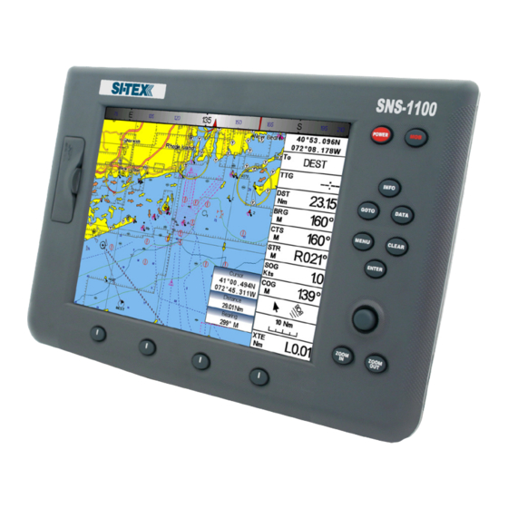
Page 105: Sns 1100
SNS 1100 FEATURES & FUNCTIONS • Direct Sun Light Viewable Color 11” LCD Display • Worldwide Built-in Cartography showing C-MAP By Jeppesen detail up to 2.0 NM • “C-MAP By Jeppesen” MAX electronic charts, object-oriented chart system with enhanced functionality including: Guardian alarm, Safety Status Bar, Safe Route Checking Perspective View Satellite Image Coverage Turbo and Smooth Zoom... - Page 106 • Navigation to Goto • Create, Save, Name, Edit, Delete, Send, Receive or Follow a Route • Route Data Report and User Points (Marks/Waypoints) List pages • Display vessel’s position, direction and Track • Alarms Handling (Auto Off, Arrival Alarm, XTE Alarm, Anchor Alarm, Depth Alarm, HDOP Alarm, Heading Alarm, Grounding Alarm, External Alarm) •...
- Page 107 CHART PLOTTER DIMENSIONS INSTALLATION AND REMOVING It is possible to install this Si-Tex instrument in “Flush Deck” mode, with space saving regard to the instrument panel plan. To make the “Flush Deck” installation it is necessary to permanently remove the silicon gasket between rear and front, placed around the chart plotter.
- Page 108 Warning Do not pull the gasket during cut operation, to avoid compromising the chart plotter watertight seal. EXTERNAL WIRING TYPICAL CONNECTIONS GPS Connection - User Manual...
- Page 109 Autopilot Connection External NMEA Connection User Manual -...
- Page 110 External Alarm Connection C-COM Connection - User Manual...
-
Page 111: Installing The Smart Gps External
Installing the Smart GPS External SNS 700e/SNS 700fe/SNS 1100 INSTALLING Choose a location for the antenna that has a clear view of the sky. Ensure there are no major obstructions or fixtures in the immediate proximity to the antenna. The antenna relies on direct “line of sight” satellite reception. If you are unsure that the chosen location is suitable it may be advisable to mount the antenna in a temporary manner to verify correct operation. - Page 112 DIMENSIONS - User Manual...
- Page 113 Notes User Manual -...
- Page 114 Si-Tex Marine Electronics 25 Enterprise Zone Drive, Suite #2 Riverhead NY 11901 USA Phone: +1-631-996-2690 Fax: +1-631-996-2693 www.si-tex.com...
Need help?
Do you have a question about the SNS-1100 and is the answer not in the manual?
Questions and answers