Table of Contents
Advertisement
Quick Links
Advertisement
Table of Contents

Related Manuals for Si-tex Explorer Nav Pro


Summary of Contents for Si-tex Explorer Nav Pro
-
Page 1: Chart Plotter
Explorer Nav Pro Chart Plotter USER MANUAL... -
Page 3: Table Of Contents
1. Disclaimer and warnings 7.3 Waypoints 2. Introduction 7.3.1 Editing waypoint’s position 2.1 Keyboard 7.3.2 Changing the order of waypoints 2.2 Connections scheme in a route 3. Getting started 7.4 Tracks 3.1 Switching ON 7.4.1 Setting up a track generation 3.2 Switching OFF interval 3.3 First Setup page... - Page 4 18.6 Transducer setup 19. System messages 20. Updates 21. Acronyms and definitions 22. Technical specifications 23. Contextual menu diagram 24. Analytic index...
-
Page 5: Disclaimer And Warnings
1. Disclaimer and warnings This user manual is intended to describe core functionality of the chart plotter. The information in this document is subject to change without notice. The manufacturer makes no representations or warranties with respect to the contents hereof and specifically disclaims any implied warranties of merchantability or fitness for any particular purpose. -
Page 6: Introduction
2. Introduction The chart plotter is a computerized electronic chart system, designed as a navigation aid. The cartplotter integrates GPS data with an electronic navigational chart and can display additional information from AIS, fish finder and other sensors. The chart plotter is compatible with both C-Map MAX and C-Map 4D map format on micro SD Card. -
Page 7: Connections Scheme
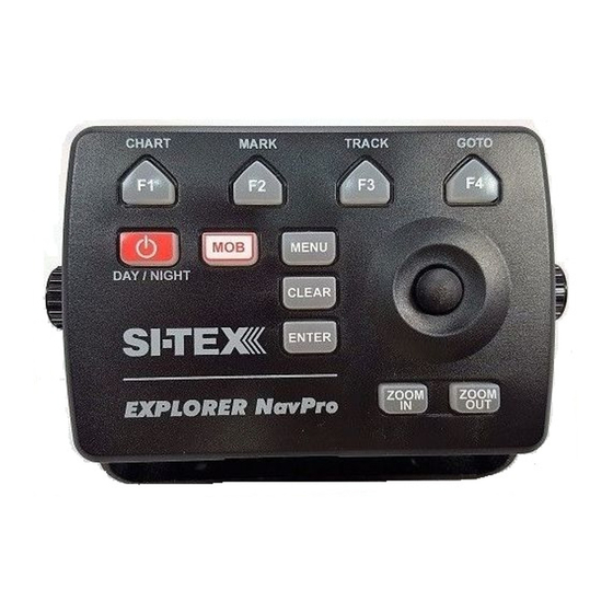
pages such as Marks, Routes, Tracks and others. 4. [JOYSTICK] can move the cursor around the map or through menu items. Press Up, Down, Left or Right. 5. [ZOOM IN] changes scale of the map. 6. [ZOOM OUT] changes scale of the map. 7. -
Page 8: Remote Controller
2.3 Remote Controller You can operate on the chart plotter using the optional remote controller. The remote controller connects to chart plotter via radio signal and requires one AAA battery. To connect the remote controller with the device: 1. On the Keyboard, press [ENTER] to open the Main Menu 2. - Page 9 position. ● [CYCLE]: cycles through pages. ● [SWITCH WHEEL FUNCTION]: changes the function of remote controller’s wheel. It has three functions on map: zoom in/out, rotate, tilt. The wheel selector can also be used to navigate through menu items as with joystick. ●...
-
Page 10: Getting Started
3. Getting started 3.1 Switching ON Before powering the chart plotter on, check for the correct voltage (10-35 volt) and the correct connections with other instruments. Press and hold [POWER] to turn on the device. It might take few minutes for chart plotter to start. 3.2 Switching OFF Press and hold [POWER] to switch the chart plotter off. -
Page 11: Selecting The Chart Language
3.5 Selecting the chart language To change the language of the chart information, which includes names of geographical objects on map, their description on Full Info page and list of objects found by search function: 1. Open the Main Menu by pressing [MENU] 2. - Page 12 2. Select “General Settings” 3. Select “Time zone” 4. Choose among UTC or Manual and press [ENTER] If you choose manual: 5. Select Time Zone and press [ENTER] 6. Select the desired zone and press [ENTER] to confirm 7. Select “Daylight Saving” and press [ENTER] to enable it (it must be enabled / disabled manually) To change time format: 1.
-
Page 13: Controlling The Display
4. Controlling the display The chart plotter displays 5 main Pages: ● Map (Par. 4.2) ● Fish Finder (Par 4.3) ● GPS status (Par. 4.4) ● Engine Monitor (Par 4.5) ● Split Map / Fish Finder page (Par. 5.5) To change displayed page: 1. -
Page 14: The Map
● Remote controller connection status ● Fish Finder connection status. 4.2 The Map The Map page includes: ● Map ● Compass bar ● Position box ● Data window. Fig 4.2.1 – Map Page During navigation you will see your Course Over Ground and bearing on the compass bar, marked with blue and red arrows respectively. -
Page 15: Fish Finder Page
Fig 4.2.2 – Map Page Menu 4.3 Fish Finder page The Fish Finder page is available only if a Black Box Fish Finder accessory is connected to the Chart Plotter. Fig 4.3.1 – Fish Finder page (simulation mode) Chart Plotter - User Manual... -
Page 16: Gps Status Page
For more details about Fish Finder see Par. 18. Press [MENU] to open Main Menu of the Fish Finder page. Fig 4.3.2 – Fish Finder Menu 4.4 GPS Status page Fig 4.4 – Example of GPS Status page Chart Plotter - User Manual... -
Page 17: Engine Monitor Display
4.5 Engine Monitor Display Fig.4.5 – Example of Engine Monitor Display page The device can be connected through CAN bus to a compatible NMEA 2000 engine, to display engine state and performance. Each parameter presented with a scale divided into three zones: green (acceptable value), yellow (warning), red (critical). -
Page 18: Split Page
4.6 Split page Fig.4.6 – Example of split page The Split page is a screen split between map and Fish Finder. Each half of the split view has its own Main Menu. When you open the split page, the active view is always the map. In order to operate on the Fish Finder view, press [MENU] twice. -
Page 19: Data Window Customization
4.7 Data window customization The Data window is a set of customizable data boxes. It is present on the map page and on the Fish Finder page. The boxes may be set up to display various sensor data. By default it consists of 10 data boxes, but you can reduce the number of displayed data boxes in General Settings, where you can turn off data window display, customize data boxes content or remove some of them. -
Page 20: Using C-Map Data (4D / Max)
5. Using C-Map Data (4D / Max) The chart plotter has a built-in background world map, but to use the chart plotter as a navigation aid, C-Map detailed chart is required. The chart plotter is compatible with both C-Map MAX and C-Map 4D map format on micro SD Card. The C-Map chart can be purchased from C-Map authorized resellers. - Page 21 There is also quick-info popup appearing automatically when you put cursor over any of the map objects. Automatic quick-info popup can be turned off: 1. Open Main Menu 2. Select “Map Settings” 3. Select “Objects on map” 4. Place cursor on “Chart Tooltip” and press [ENTER] 5.
-
Page 22: Go To Function
6. GO TO function 6.1 Navigation to a single destination [GO TO] 1. Place cursor at a desired position on map 2. Press [ENTER] to open contextual menu 3. Select “Go To” 4. Press [ENTER] to confirm selection 6.1.1 Map with cursor contextual menu A straight gray line is shown on the screen connecting the destination with the initial boat's position (departure point). -
Page 23: Creating A Route
6.1.2 Map with Active navigation 6.2 Creating a route A route consists of a set of waypoints. To create a route from the routes list page: 1. Press [MENU] 2. Select “Routes” 3. Press [ENTER]. 4. Select “Create new” in the top bar menu 5. -
Page 24: Route Following
6.2. Map in new route creation mode After the route has been created, you will see dialog window, asking whether you want to navigate to newly created route. Press Ok to start the navigation to route. When you create new route, it has default color and prefix “Route” with incrementing number. You can change default color or prefix: 1. -
Page 25: Route Following Optimization
3. Select “Start nav” to start navigating to route, beginning from the nearest waypoint to your boat position. 4. Select “Start here” to start navigating to route, beginning from this particular waypoint. 5. Select “Go To” to start navigating to the single destination (and not to route). When you reach first waypoint, navigation will be started to the next waypoint automatically. -
Page 26: Route Following Options
6.3.2 Route following options Most of the route following options can be modified from map with no need to open Route's page. Inserting a Waypoint During navigation you may want to first reach another point on map, and only then navigate to the initial destination. -
Page 27: Easy Routing
2. Press [ENTER] 3. Select “Delete route” 4. Press [ENTER]. You can delete a waypoint a route only if it is not a current destination. To delete waypoint use “Delete WP” option in waypoint’s contextual menu. Reversing a route To reverse navigation direction, use “Reverse” option in waypoints contextual menu. You can reverse route from map only if you are in navigation mode. - Page 28 The program will find obstacles between two waypoints and re-build it so that obstacles will be avoided. The program's decision about avoiding obstacles on your way is based on information about your boat parameters (safe corridor, depth, height, length). 1. Place cursor on a route leg (a line, that connects two waypoints). 2.
-
Page 29: User Data
7. User Data User data point is an object that you can place on the charts to mark a specific point and get it stored in chart plotter’s database. The chart plotter has the following types of user data: Marks Events, Tracks, Route and Waypoints. A Mark can be created on the cursor’s position while an Event is created on boat’s position. - Page 30 7.1.1 Adding new mark To add a mark in marks list: 1. Press “Add new” button in top bar menu 2. Select the way to create a waypoint – “Use fix” or “Manually” 3. Press [ENTER] “Use fix” creates event on fix position. “Manually”...
-
Page 31: Editing Mark's Color, Symbol, Name And Description
4. Select “Save event” 5. Press [ENTER]. 7.1.2 Editing Mark’s color, symbol, name and description You can change a color, symbol, name and description of a single mark. In Mark’s list: 1. On map page press [MENU] 2. Open “Marks” 3. -
Page 32: Routes
7.2 Routes Routes can be created, modified or deleted in routes lists and on map. To open routes list: 1. Press [MENU] 2. Select “Routes” 3. Press [ENTER]. Fig.7.2 – Routes page On this page you can observe all routes that are stored on your chart plotter, and open list of waypoints of a selected route. -
Page 33: Editing A Route's Color, Name And Description
7.2.2 Changing routes order in list Order of routes in routes list can be changed. You can sort out the routes by number, color, status (active/inactive/hidden), name, date of creation, number of waypoints and total distance. 1. Press the “Order by” button to enable the changing order mode 2. -
Page 34: Waypoints
7.3 Waypoints Each route is a set of waypoints. List of waypoints can be accessed either from map or from route’s page. Waypoints can be added to route either on map or on the route’s page. 1. Open Routes page 2. -
Page 35: Changing The Order Of Waypoints In A Route
On map: 1. Place cursor over the waypoint on map 2. Press [ENTER] to open menu 3. Select “Move” 4. Press [ENTER] 5. Move cursor over map 6. Press [ENTER] to save new position You can also change waypoint position by inputting new lat/lon position manually. In this case select “Edit Position”... -
Page 36: Setting Up A Track Generation Interval
Fig.7.4 – Tracks page 7.4.1 Setting up a track generation interval By default track records your position every 1 second. There are two possible algorithms of track generation: by Distance and by Time. If Distance - a track point is placed when the distance from its last stored position is greater than the defined distance;... -
Page 37: Displaying Track
7.4.2 Displaying Track To enable or disable the Track displaying on the map screen: 1. On map page press [MENU] 2. Select “Tracks” 3. Press “Hide all” to hide all tracks 4. Select a track in list and press [ENTER]. Select “Hide” to hide only this track 7.4.3 Converting Track to Route You can convert a track to route, so that the new route will outline the boat’s track. -
Page 38: Changing User Data Default Color, Symbol Or Prefix
7.6 Changing user data default color, symbol or prefix New route, mark, event and track will be created with default color, symbol and name with incrementing number. To change defaults: 1. In Marks, Tracks or Routes list select “More” and press [ENTER] 2. -
Page 39: Exporting / Importing User Data
7.7 Exporting / importing user data You can export or import your user data to or from a micro SD card. To export user data: 1. Insert a micro SD card to the micro SD slot of the chart plotter 2. -
Page 40: A-B Function
8. A-B function The A-B function allows measuring the distance and bearing between two points on the map page. You can access the A-B function in the contextual menu of map. 1. Open the map page 2. Press [ENTER] 3. Select “A-B” 4. -
Page 41: Search Function
9. Search function Search function is aimed to help you to find objects on map. Objects are found in a range around cursor position, which you can vary. Fig.9 – Search menu NOTE Search function requires detailed C-Map chart, unless you search Marks. In the map page: 1. - Page 42 of search. The larger range is covered by search, the longer it takes. You can interrupt search operation by pressing [ENTER] on the “Searching...” status window. 6. The full info page of the selected object opens, where you can read information about the object, as well as locate the object on map or start navigation to it.
-
Page 43: Tide Info
10. Tide info The Tide Graph page displays a graphical page with the tides prediction of the selected object. 1. Search for a Tide Station 2. Select a station and press [ENTER] 3. In the Full info page press “Tide Graph” Otherwise 4. - Page 44 Press [DOWN] in order to select the tide graph. You can move cursor along the tide graph to see its height for the specific time pressing left or right. Press [UP] in order to move cursor back to the “Change date” button. Press [CLEAR] to exit Tide Graph page.
-
Page 45: Mob
11. MOB If a person or object is lost overboard and you need to return to the location, use the MOB (Man Over Board) function. To activate the MOB function, a valid GPS fix must be available. MOB function can be accessed from any page by pressing [MOB] key of the chart plotter. The MOB mark is placed on the current fix position and at the same time navigation towards the MOB position starts. -
Page 46: Alarms
12. Alarms The chart plotter provides alarms for various purposes: navigation, fishing, engine and AIS monitoring. You can specify the desired alarm range for most of the functions. To open Alarms page: 1. Press [MENU] on the map page 2. Select “Alarms” 3. - Page 47 ● XTE alarm: is triggered when the vessel is deviating from a defined course. ● Arrival alarm: is triggered when the distance to destination becomes smaller than specified in the alarm settings. ● HDOP alarm: triggered when the received HDOP value exceeds the alarm limit. By default all navigation alarms are turned off.
- Page 48 Fish Finder alarms The Fish Finder alarm is available only when a compatible echo sounder module is connected to the chart plotter. Fish Finder alarms include: ● Shallow water alarm: triggered, when depth, detected by Fish Finder transducer is too shallow.
-
Page 49: Simulation Mode
13. Simulation mode The built-in Simulator function allows you to become proficient in the use of the chart plotter. It simulates reception of the navigation data (Lat/Lon, Course, Speed). The simulated boat’s position is placed at the then current position of cursor when the simulation is activated. To turn fix simulation on: 1. -
Page 50: General Settings
14. General settings To access General Settings page: 1. Press [MENU] on any page 2. Select “General Settings” 3. Press [ENTER] This page is dedicated to setting general functions. Fig.14 – General settings menu 14.1 Export/Import User Settings Exporting and importing user settings to micro SD card can be done on Log&Backup page. 1. -
Page 51: Function Keys Settings
1. Insert micro SD card with a configuration file into the chart plotter 2. Open General Settings page 3. Select “Log&Backup” 4. Press [ENTER] 5. Select “Import configuration” 6. Confirm your action By importing configurations from micro SD card you overwrite your current settings of the chart plotter. -
Page 52: Keyboard Settings
● Automatic route following (see Par. 6.2) ● Route following optimization (see Par. 6.2) ● Arrival circle radius (see Par. 6.2) ● Screen amplifier (see Par. 5.2). 14.4 Keyboard Settings On the keyboard page you can change settings for keyboard, such as beep sound on key press, cursor speed and keyboard backlight. -
Page 53: Ship Profile Settings
7. In case of “Custom” select “Brightness” 8. Press [ENTER] 14.5 Ship Profile Settings It is important to enter correct information about your vessel’s parameters on the Ship Profile page. 1. Open General Settings page 2. Select “Ship Profile” 3. Press [ENTER] Fig.14.5 –... -
Page 54: Map Settings
15. Map settings 15.1 Course Predictor The Course predictor line is a line that starts from your boat and indicates the course direction. It is presented on map with an infinite blue dashed line. You can customize it in the Course predictor settings: 1. -
Page 55: Map Orientation
You can switch the heading line OFF in the same way. 15.3 Map Orientation During navigation the map can be fixed with north up, or it can be oriented as to keep the Route Up (destination), or course up. Otherwise you can choose a fixed custom map orientation, rotating the map using the remote control. -
Page 56: Ports Settings
16. Ports settings You can changes the parameters of the serial and CAN interface on the Ports and Connectivity page. 1. Press [MENU] on any of the main pages 2. Select “Ports and Connectivity” 3. Press [ENTER] You can find configuration pages for serial ports A, B, C and CAN port. 16.1 NMEA0183 serial ports The chart plotter is equipped with three serial ports (COM) and one CAN port. -
Page 57: View Port Incoming Data
5. Press [ENTER] to open the “Output options” page 6. Press [ENTER] on the “Enable output” button On the “Output options” page you can select: ● the NMEA talker ID to use as a prefix for NMEA 0183 sentences ● the NMEA 0183 version (2.0, 3.0 or 4.1) ●... -
Page 58: Ais
17. AIS AIS is an Automatic Identification System. The AIS allows automatic tracking of ships for identifying and locating vessels by exchanging data with other nearby ships, AIS base stations, and satellites. A vessel equipped with AIS is called a Target. Information about the Targets is being received by AIS Receiver and displayed on the screen and in the AIS page: 1. - Page 59 Fig. 17.1.1 – AIS Target with track shown on the map AIS Target class In order to apply the AIS class speed filter select the classes you want to be displayed on map and on the AIS Targets page. AIS Target information On the AIS Targets page you can access the following information: ●...
- Page 60 Fig. 17.1.2 – AIS Target info box On this page you can start/stop tracking of the selected AIS Target and locate it on the map. By placing the cursor over an AIS Target icon on the map, the following information is displayed: AIS name, SOG, COG, CPA and TCPA (see Fig.
-
Page 61: Fish Finder
18. Fish Finder The Fish Finder consists of a high power transmitter, sensitive receiver and a transducer. The Fish Finder sends acoustic (sound) wave through the water. As this wave travels from the transducer to the bottom, it may strike fish, structures, thermoclines (temperature changes in the water). - Page 62 1. Fish Finder icon in the status bar, it means the fish finder is connected and active. 2. Color bar is a colored scale located on the left side of the screen that shows the colors used in the echogram to represent the echoes strength. The color on the top of the bar represents the maximum sonar strength, while the color on the bottom of the bar represents the minimum sonar strength.
- Page 63 18.3 Echogram history The Echogram presents an approximate picture of the surface under the Fish Finder transducer that can be scrolled to see the history of the echoes received by the transducer. To scroll the echogram: 1. Open Fish Finder page 2.
-
Page 64: Frequency
1. Move vertical time marker with joystick to place it in the desired position 2. Press [ENTER] 3. Select “Create Mark” 4. Press [ENTER] The mark is placed and saved at the place where your boat was located at that exact time moment. -
Page 65: Sensitivity Setup
1. On Fish Finder page press [MENU] 2. Select “Frequency kHz” 3. Press [ENTER] When operating in double frequency (200/50 kHz) Fish Finder's page is divided into two sides. Move cursor between them to operate on either side: 1. Press [Menu] 2. -
Page 66: Transducer Setup
In Bottom Lock Mode the Fish Finder automatically tracks the range around the bottom specified by the Bottom Range value. If the range is set to Manual, it can be changed by zooming in/out on the Fish Finder page. Zooming in/out can be done with ZOOM IN and ZOOM OUT keys of the chart plotter, and with the wheel of the remote control. - Page 67 the transducer. ● Calibrate water temperature: calibrates the water temperature sensor. Using the readings from a precise temperature measuring device, insert here a positive/negative offset to display correct value on the Fish Finder screen. ● Calibrate auxiliary water temperature: calibrates the Aux Temperature sensor. Using the readings from a precise temperature measuring device, insert here a positive/ negative offset to display correct value on the Fish Finder screen.
-
Page 68: System Messages
19. System messages System messages page lists the history of all the Warning messages and Alarms with the date and time when they appeared. To access System Messages: 1. Press [MENU] on any of the main pages 2. Select “System messages” 3. -
Page 69: Updates
20. Updates You can check your device Software version in the “Device Info” page. 1. Press [MENU] 2. Select “General Settings” 3. Press [ENTER] 4. Select “Device Info” 5. Press [ENTER] Ask your customer support center for software update procedures. Chart Plotter - User Manual... -
Page 70: Acronyms And Definitions
21. Acronyms and definitions ● ALT = Altitude Altitude of GPS Antenna on the medium sea level. ● Alter = Alternate Solution (TD Coordinates System) Parameter selected by the user that is applied in the conversion of TD values to geographical coordinates Lat/Lon. - Page 71 ● Depth Line (Also called Bathymetric Line) Imaginary line connecting points of equal water depth. ● Destination In order to tag on the chart the point, towards which the ship is Heading, you can use a special mark, called destination. When the destination is placed, all navigation data referred to this point. ●...
- Page 72 ● Home mode All operations refer to the ship’s position. ● Landmarks Landmarks are any prominent object such as monument, building, silo, tower, mast, etc on land which can be used in determining a location or a direction. ● Latitude Angular distance North or South of the equator measured by lines encircling the earth parallel to the equator in degrees from 0°...
- Page 73 the map: they can be the landscape layout nearby a harbor, the shape of a bridge or of a buoy etc. On some objects, such as bridges, the image associated can represent the Diagram representing the shape of the objects and the various characteristics (length, height, type of bridge etc.).
- Page 74 ● Tide Info Calculates the tide heights for any past or future date and as a by-product of this calculation will also display the Maximum and Minimum Tide height and time for the day selected plus the times of Sunrise and Sunset. At some chart levels, the chart plotter will display a new Tide Diamond Symbol for every Port or tide point in the database covered by that particular DATA MEDIA.
- Page 75 navigation. After achieving initial operational capability, the WAAS will then be incrementally improved over the next years to expand the area of coverage, increase the availability of precision approaches, increase signal redundancy and reduce operational restrictions. ● Waypoint Any point to which one intends to navigate. A sequence of Waypoints makes up a Route plan. ●...
-
Page 76: Technical Specifications
22. Technical specifications ● Dimensions: 172.5 x 106.5 x 84.4 mm (6.8” * 4.2” * 3.3” ) with holder ● Weight: 350 g (12.3 oz) ● Compatible with any HDMI display ● Power consumption: 1.2W typical ● Supply Voltage: 10-35 Vdc ●... -
Page 77: Contextual Menu Diagram
23. Contextual menu diagram Note In navigation means that the user is following destination of any kind (mark, WP, Route etc...) Map background no nav*: Map background in Map background in 1. Go to navigation*: navigation (active route)*: 2. Tide Graph** 1. - Page 78 Route last WP in Route last WP in navigation, Route leg no nav*: 1. Start nav navigation*: current destination*: 2. Start here (next wp after the 1. Stop nav 1. Stop nav leg) 2. Start here 2. Extend 3. Go To 3.
-
Page 79: Analytic Index
24. Analytic Index 70, 72 Stop navigation 22, 26, 45 List of waypoints 34 Surface noise 65 A-B function 40 Data box 19 System language 10 AIS icon 60 Daylight saving 12 System messages 62, 68 AIS page 58 Depth alarm 46 Main menu 6, 8, 14, 16, 18 AIS class 59 Depth ruler 62... - Page 80 MAMC1XXAE020 ÑMAMC1XXAE020qÓ...
Need help?
Do you have a question about the Explorer Nav Pro and is the answer not in the manual?
Questions and answers
Where is main menu button on nav pro 1200
How do I turn off my own position on my SI-TEX explorer Navpro