Altusen PN9108 User Manual
Hide thumbs
Also See for ALTUSEN PN9108:
- User manual (70 pages) ,
- Quick start manual (2 pages) ,
- Specification (1 page)
Table of Contents
Advertisement
Quick Links
Advertisement
Table of Contents

Related Manuals for Altusen ALTUSEN PN9108


Summary of Contents for Altusen ALTUSEN PN9108
- Page 1 Power over the NET™ PN9108 User Manual www.aten.com...
-
Page 2: Fcc Information
PN9108 User Manual FCC Information This is an FCC Class A product. In a domestic environment this product may cause radio interference in which case the user may be required to take adequate measures. This equipment has been tested and found to comply with the limits for a Class A digital device, pursuant to Part 15 of the FCC Rules. -
Page 3: User Information
PN9108 User Manual User Information Online Registration Be sure to register your product at our online support center: International http://support.aten.com North America ATEN TECH http://www.aten-usa.com/product_registration ATEN NJ http://support.aten.com Telephone Support For telephone support, call this number: International 886-2-8692-6959 North America... -
Page 4: Package Contents
Copyright © 2004-2007 ATEN® International Co., Ltd. Manual Part No. PAPE-0254-1AXG Printing Date:12/2007 Altusen and the Altusen logo are registered trademarks of ATEN International Co., Ltd. All rights reserved. All other brand names and trademarks are the registered property of their respective owners. -
Page 5: Table Of Contents
PN9108 User Manual Contents FCC Information ..........ii SJ/T 11364-2006. - Page 6 PN9108 User Manual Chapter 4. Administration Working Environment Configuration ......19 General ..........19 Network .
- Page 7 PN9108 User Manual Indirect Dial In Connection (PPP) ....... 60 Connection Setup .
-
Page 8: About This Manual
PN9108 User Manual About This Manual This User Manual is provided to help you get the most from your PN9108 system. It covers all aspects of installation, configuration and operation. An overview of the information found in the manual is provided below. Overview Chapter 1, Introduction, introduces you to the PN9108 system. -
Page 9: Conventions
For information about all ALTUSEN products and how they can help you connect without limits, visit ALTUSEN on the Web or contact an ALTUSEN Authorized Reseller. Visit ALTUSEN on the Web for a list of locations and telephone numbers International – http://www.aten.com North America – http://www.aten-usa.com... - Page 10 PN9108 User Manual This Page Intentionally Left Blank...
-
Page 11: Chapter 1 Introduction
Chapter 1 Introduction Overview The PN9108 Power over the NET™ is a control unit that provides remote power management for eight AC outlets via a TCP/IP connection, allowing administrators to control the power off, power on, and reboot status for each attached device from any computer connected to the Internet, whether down the hall, or half way around the world. -
Page 12: Features
PN9108 User Manual Features Remote power on/off/reboot control for eight outlets via TCP/IP and a built in 10/100 Ethernet port Local power on/off/reboot control via the PN9108's RS-232 port to the computer's RS-232 port Daisy chain up to 15 additional stations to control up to 128 outlets Manual switching between Local and Remote access for each port via front panel push button switches Individual control of each port - users can set the power on sequence and... -
Page 13: Requirements
Chapter 1. Introduction Requirements Browsers accessing the PN9108 must support SSL 128 bit encryption. For cold booting of attached computers, the computer's BIOS must support this feature. For Safe Shutdown: The computer must be running Windows (Windows 98 or higher). The computer's BIOS must support Safe Shutdown. -
Page 14: Components
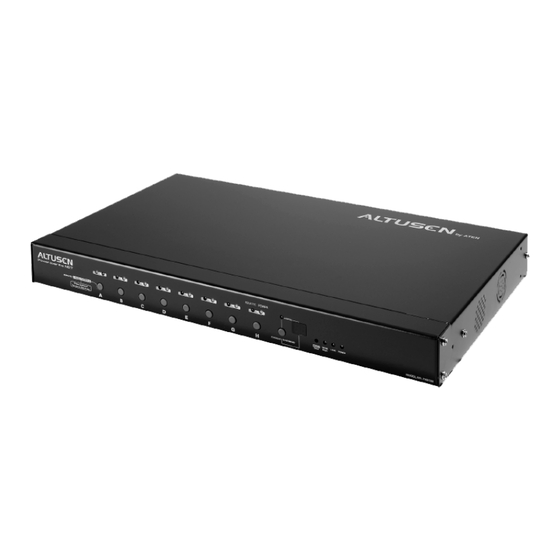
PN9108 User Manual Components Front View Item Description Port LEDs The Port LEDs provide status information about their corresponding AC outlet ports. There is one pair of LEDs for each port. The one on the left is the Remote Access LED; the one on the right is the Power LED: A Remote Access LED lights GREEN to indicate that the device attached to its corresponding port is capable of being controlled... - Page 15 Chapter 1. Introduction (Continued from previous page.) Item Description Station ID The PN9108's Station ID usually displays here. If this is a Single Station installation (see page 10), or the First Station on a Daisy Chained installation (see page 12), the PN9108 has a Station ID of 01.
-
Page 16: Rear View
PN9108 User Manual Rear View Item Description Power The power cable from the AC source plugs in here. Socket Circuit Press to reset the circuit. Breaker AC Power The power cables that connect to the computers plug in here. Outlets RS-232 This port can be used to attach a UPS, modem, or PC terminal. -
Page 17: Chapter 2. Hardware Setup
Chapter 2 Hardware Setup Before You Begin 1. Important safety information regarding the placement of this device is provided on page 67. Please review it before proceeding. 2. Make sure that power to all the devices you will be connecting up have been turned off. -
Page 18: Rack Mounting
PN9108 User Manual Rack Mounting The PN9108 can be installed in most standard 19" (1U) racks. To rack mount the unit do the following: 1. Separate the front and rear modules by removing the four module attaching screws: Phillips hex head M3 x 8 2. - Page 19 Chapter 2. Hardware Setup Note: Cage nuts are provided for racks that are not prethreaded.
-
Page 20: Single Stage Installation
PN9108 User Manual Single Stage Installation In a Single Stage installation, there are no additional PN9108 Stations daisy chained down from the first unit. To set up a single stage installation, refer to the installation diagram below (the numbers in the diagram correspond to the numbered steps), and do the following: 1. - Page 21 Chapter 2. Hardware Setup...
-
Page 22: Daisy Chaining
PN9108 User Manual Daisy Chaining To manage even more devices, up to 15 additional PN9108 Stations can be daisy chained down from the top level unit. In this way, up to 128 devices can be managed on a complete installation. To set up a daisy chained installation do the following: 1. -
Page 23: Chapter 3. Browser Operation
Chapter 3 Browser Operation Logging In The PN9108 is accessed with an internet browser. Note: Browsers accessing the PN9108 must support SSL 128 bit encryption. 1. Open your browser and specify the IP address of the PN9108 you want to access in the browser's URL location bar. -
Page 24: The Pn9108 Main Screen
PN9108 User Manual The PN9108 Main Screen After you have successfully logged in, the PN9108 Main Screen appears: The icons arranged horizontally across the top are used by the administrator to configure the PN9108's working environment. Administrative functions are explained in Chapter 4. The bar along the left side is used to configure and control each of the PN9108 Stations on your installation. -
Page 25: Device Selector
Chapter 3. Browser Operation Device Selector Since up to 16 PN9108 Stations can be daisy chained, this panel lists each of the Stations on your installation. The number in brackets, to the right of the title, indicates the total number of stations on the installation. -
Page 26: The Power Status Screen
PN9108 User Manual The Power Status Screen The Top Panel Power Buttons: The top panel of the Power Status screen is divided into eight subareas which correspond to the A- H outlets on the PN9108's rear panel. Each subarea is composed of a socket icon that functions as the Power Button for its corresponding outlet, and an information panel to its right. - Page 27 Chapter 3. Browser Operation The Information Panel: The information panel shows the Outlet's name and currently selected power option. These parameters are set by the Administrator with the Configuration function (see page 26 for details). Reboot: If Reboot is enabled (by putting a check in the checkbox), the computer attached to the Outlet's corresponding port will reboot instead of shutting off when the Power Button is clicked to turn the outlet off.
-
Page 28: The Bottom Panel
PN9108 User Manual The Bottom Panel The bottom panel allows you to control the power status of your outlet groups. Outlets can be placed into groups so that Power On/Off actions can be carried out on the entire outlet group at the same time, rather than performing the same action on each outlet individually. -
Page 29: Chapter 4. Administration
Chapter 4 Administration Working Environment Configuration The icon bar at the top of the main screen is used by the administrator to configure the PN9108's working environment. An explanation of each of the configuration functions is given in the sections that follow. - Page 30 PN9108 User Manual System Information: The System Information section allows you to provide a name and description for the PN9108 installation. Providing a name and description is optional, but makes it convenient for system operators to distinguish among installation groups in large, installations when there are several groups of daisy chained PN9108s The name can be up to 30 characters.
-
Page 31: Network
Chapter 4. Administration Network Network Settings allows you to choose how the PN9108 functions on the network. IP Address Settings: Fixed IP Address: The default is for a fixed IP address. To give the PN9108 a fixed IP address, fill in the Network Settings and DNS Settings fields with values appropriate to the network you are on. - Page 32 PN9108 User Manual (Continued from previous page.) Dynamic IP Address: To have the Station obtain its IP address automatically from a DHCP server, select the DHCP radio button. When you do, the fields in the Network Settings section are disabled, and a Mail Configuration panel appears: 1.
-
Page 33: Service Ports
Chapter 4. Administration Service Ports: The values shown in the dialog box are the default settings. If you change them, users must specify the port as part of the URL when logging in. If you change the http port to 81, for example, users must log in as follows: http://10.0.100.65:81 IP Installer Settings: To help determine and/or set an IP address for a PN9108 an IP Installer utility... -
Page 34: Date / Time
PN9108 User Manual Date / Time The Date / Time function allows you to set the PN9108's system date and time. When you click the Date / Time icon, the following dialog box appears: The date and time settings that the PN9108 is currently set to appear in the upper section. -
Page 35: Firmware
Chapter 4. Administration Firmware The Firmware upgrade function allows you to upgrade the PN9108's firmware. When you click the Firmware icon, the following dialog box appears: Logout Click the Logout icon to end your PN9108 session. Note: It is important to log out when you end your session. Otherwise, you must wait until the timeout setting has expired before the PN9108 can be accessed again. -
Page 36: Power Management Configuration
PN9108 User Manual Power Management Configuration The buttons in the Device Control panel allow the PN9108 administrator to configure the power management functions of each of the PN9108 Stations on the installation. The functions provided by each of the buttons are explained in the sections that follow. - Page 37 Chapter 4. Administration The top Configuration panel allows you to set up a power management configuration for each port. These settings determine what takes place when you click the Power Button On or Off. The meanings of the field headings are given in the following table: Heading Meaning...
- Page 38 PN9108 User Manual (Continued from previous page.) Heading Meaning Kill the Power If this option is selected, the PN9108 waits for the amount time set in the Power Off Delay field (see below), and then turns the Outlet's power OFF when its Power Button is clicked to turn off the power.
- Page 39 Chapter 4. Administration Outlet Groups: The bottom Configuration panel (refer back to page 26) lets you select the outlets that you want to put together as an outlet group. Outlet groups enable control actions to be carried out on the entire group at the same time, rather than repeatedly performing the same action on each individual outlet.
- Page 40 PN9108 User Manual It is also possible to attach an individual UPS for each computer to the PN9108's outlet ports. In this case: Do not enable the PN9108's UPS function - since that function only works with a UPS device attached to its RS-232 port. Configure the UPS devices according to the documentation provided with each of them.
-
Page 41: Schedule
Chapter 4. Administration Schedule Clicking the Device Control Schedule button brings up the Scheduling dialog box: This dialog box allows you to set up a scheduled Power On/Off configuration for each of the outlets. To do so: 1. Select your outlet from the buttons in the upper panel. 2. -
Page 42: User Management
PN9108 User Manual User Management Clicking the Device Control User Manager button brings up the User Management dialog box: This dialog box allows the Administrator to set up Usernames and Passwords that operators must provide in order to log into the PN9108. The minimum number of characters for each field is 4;... -
Page 43: Monitor
Chapter 4. Administration Monitor Clicking the Device Control Monitor button brings up the Device Monitor display: This display shows the power status of your entire installation. You can see at a glance what the total current load for each of the Stations on the installation is, as well as the On/Off status of each outlet. -
Page 44: Log
PN9108 User Manual Clicking the Device Control Log button brings up the Event Log dialog box: The PN9108 maintains a log file of the last 2048 events that took place on it. This dialog box allows you to select the range of events you wish to view: Choose Today then click OK to see a listing of only today's events. - Page 45 Chapter 4. Administration Once you make a choice and click OK an Event Log List, similar to the one below, appears: When you have finished viewing the event list: If you want to return to the Event Log dialog box, click Back. If you want to erase the contents of the entire log file, click Clear All.
- Page 46 PN9108 User Manual This Page Intentionally Left Blank...
-
Page 47: Safe Shutdown And Reboot
Chapter 5 Safe Shutdown and Reboot Overview The PN9108's Safe Shutdown and Reboot functions are available for systems running Windows. Safe shutdown and reboot lets you safely close a system down and reboot it without involving the danger to the file systems that simply killing the power supply does. -
Page 48: Automated Setup
PN9108 User Manual 4. The wording for the System after AC Back function may vary somewhat from system to system. For example: AC Loss Auto Restart Restore on AC Power Loss In the BIOS settings, choose Power On (Full On). 5. -
Page 49: Uninstalling
Chapter 5. Safe Shutdown and Reboot By default, PMonitor monitors the COM1 port. If the utility displays an error message stating that it is unable to open the COM1 port, it means that the port is already being used by another utility. You can either stop the other utility, and try again, or use a different COM port for the PMonitor program. -
Page 50: Manual Setup
PN9108 User Manual Manual Setup Windows NT, 2000, XP, and Server 2003 can be manually configured for safe shutdown and rebooting instead of using the Power Monitor utility. The following sections explain the procedures involved. Windows 2000 / XP / Server 2003: To set up Windows 2000, XP, or Server 2003 for safe shutdown and rebooting, do the following: 1. - Page 51 Chapter 5. Safe Shutdown and Reboot 2. Click Next. A dialog box similar to the one below appears: Select the options in the dialog box so that they match the settings shown in the figure above. 3. Click Finish; click OK. To check that the setup is working: 1.
- Page 52 PN9108 User Manual 1. Go to the Control Panel; open the UPS entry. A dialog box similar to the one below appears: a) For the COM port entry, select the COM port on the computer that the Safe Shutdown Cable is plugged into. b) Match the other options to the values shown in the figure above.
-
Page 53: Chapter 6. Out Of Band Operation
Chapter 6 Out of Band Operation In case the LAN that the PN9108 resides on goes down, or the PN9108 cannot be accessed with the usual browser based method for some other reason, the PN9108 can be accessed via several Out of Band methods utilizing the PN9108's RS-232 port in the following ways: Connect the RS-232 port to the COM port of a local computer to operate the PN9108 Station from a local computer's console terminal... -
Page 54: Computer Connection
PN9108 User Manual Enable OOB operation by clicking to put a checkmark in the Out Of Band Enable checkbox. Note: Since OOB operation and UPS operation both require the use of the RS-232 port, enabling OOB automatically disables the PN9108's UPS feature. -
Page 55: Modem Connection
Chapter 6. Out of Band Operation Modem Connection The modem connection function makes it possible to access the PN9108 from a remote location with a dial in terminal connection; a dial in PPP connection; or a dial out connection. For the dial out function, you must establish an account with an ISP (Internet Service Provider), and then use a modem to dial up to your ISP account. - Page 56 PN9108 User Manual 4. If you want the PN9108 to be able to dial out, activate the dial out function by putting a checkmark in the Enable dial out checkbox. Note: Unless this function is enabled, you will only be able to dial in. None of the Dial Out Schedule functions (described below) will occur.
-
Page 57: Dialog Box Buttons
Chapter 6. Out of Band Operation 8. If the network goes down, or the PN9108 gets disconnected from it, the Emergency dial out function puts the PN9108 on line via the ISP dial up connection. If you choose PPP keeps online until network recovery, the PPP connection to the ISP will last until the network comes back up or the PN9108 reconnects to it. -
Page 58: Direct Terminal Connection (Hyperterminal)
PN9108 User Manual Direct Terminal Connection (HyperTerminal) HyperTerminal Setup 1. Use a 9 pin null modem cable (pin 2 to pin3; pin 3 to pin2) to connect a COM port on a PC to the PN9108's RS-232 port. Note: The null modem cable must be wired for either full or loop back handshaking. - Page 59 Chapter 6. Out of Band Operation The following dialog box comes up: 3. For the Connect using: field, select Direct to COM1 (assuming you are using COM1 on your computer), then click OK. A Port Setting dialog box similar to the one below comes up:...
- Page 60 PN9108 User Manual 4. For OOBC connections, the PN9108's serial port settings and the computer's COM port settings must be the same. Change the settings in your dialog box (if necessary), so that they match the PN9108's COM Port settings (see Modem Connection, page 45, for details), then click OK. Note: The PN9108's default settings are 115200 bps;...
-
Page 61: Logging In
Chapter 6. Out of Band Operation 6. Change the settings (if necessary), so that they match the settings shown in the diagram, then click ASCII Setup... The ASCII Setup dialog box comes up: 7. Change the settings (if necessary), so that they match the settings shown in the diagram, then click OK. -
Page 62: Indirect Terminal Connection (Hyperterminal)
PN9108 User Manual Indirect Terminal Connection (HyperTerminal) Connection Setup 1. Set up your hardware configuration to match the diagram, below: PN9108 Serial Cable Serial Cable Phone Line Remote Operator Modem Modem Note: 1. Use standard 9 pin serial modem cables to connect to the modems. -
Page 63: Final Check
Chapter 6. Out of Band Operation Final Check To make sure that the modem and COM port are correctly installed: 1. Open the Control Panel: My Computer → Control Panel 2. Open the Make New Connection folder. If all went well, you should see an entry with the name you assigned for this connection. -
Page 64: Logging In
PN9108 User Manual Logging In 1. In the Out of Band Configuration dialog box (see page 45), make sure that the Enable dial-out function setting is disabled (the box is unchecked), and that the PN9108's baud rate is set to 115200. 2. -
Page 65: Direct Dial In Connection (Ppp)
Chapter 6. Out of Band Operation Direct Dial In Connection (PPP) This type of connection works directly through the COM port. Connection Setup 1. Use a 9 pin null modem cable to connect a COM port on a PC to the PN9108's RS-232 port. - Page 66 PN9108 User Manual 3. Key a name of your choice in the top text box; select Standard 28800 bps Modem for the device; then click Configure. The Modem Properties dialog box comes up: Change your settings (if necessary), so that they match the settings shown in the figure above (assuming you are using COM1 - if not choose a port setting that matches the COM port you are using).
- Page 67 Chapter 6. Out of Band Operation 5. Change your settings (if necessary), so that they match the settings shown in the figure above; then click Advanced. The Advanced Connection Settings dialog box appears: 6. If there is a check mark in the Use flow control checkbox, uncheck it, then click OK.
-
Page 68: Finishing Up
PN9108 User Manual Finishing Up 1. Right click on the icon you just created, and select Properties. In the dialog box that appears, select the Server Types tab: 2. Match the checkboxes in the dialog box to the ones in the diagram, then click TCP/IP Settings. -
Page 69: Logging In
Chapter 6. Out of Band Operation 3. Change the dialog box settings to match the ones in the diagram. Note: The IP address can be any address in the same network segment as the PN9108 (but not the same IP address as the PN9108). 4. -
Page 70: Indirect Dial In Connection (Ppp)
PN9108 User Manual Indirect Dial In Connection (PPP) This method uses a modem connection to phone into the PN9108 from a remote location. Connection Setup 1. Set up your hardware configuration to match the diagram, below: PN9108 Serial Cable Serial Cable Phone Line Remote Operator... -
Page 71: Finishing Up
Chapter 6. Out of Band Operation Finishing Up This step is the same as for a direct dial in connection. See page 58 for details. Logging In 1. In the Out of Band Configuration dialog box (see page 45), make sure that the Enable dial-out function setting is disabled (the box is unchecked), and that the PN9108's baud rate is set to 115200. -
Page 72: Dial Out Connection
PN9108 User Manual Dial Out Connection This configuration sets up a connection for the PN9108 to an ISP's site. You can use the dynamic IP address that the ISP assigns to the PN9108 to access it with a browser. Connection Setup 1. -
Page 73: Logging In
Chapter 6. Out of Band Operation c) If you choose, you can set up a dial out schedule that puts the PN9108 on line over the internet via the ISP account by filling in the Dial-out Schedule information. See p. 46 for Dial-out Schedule details. d) Use the Mail Configuration section of the dialog box to have the PN9108's IP address (as assigned by the ISP) emailed to the people you want to access it. -
Page 74: Telnet
PN9108 User Manual Telnet Terminal Access 1. On your computer, open a terminal (command line) session. 2. At the prompt, key in the following: telnet [PN9108's IP Address] Note: The IP address is assigned by your ISP. 3. Press Enter 4. -
Page 75: Upgrading The Firmware
Chapter 7 Upgrading The Firmware The Firmware Upgrade Utility provides a smooth, automated process for upgrading the PN9108's firmware. New firmware upgrade packages are posted on our web site as they become available. Check the site regularly to find the latest packages. -
Page 76: Starting The Upgrade
PN9108 User Manual Starting the Upgrade To start the upgrade, do the following: 1. From the computer that you downloaded the upgrade file to, log into the PN9108. 2. Click the Firmware icon. The Firmware Upgrade dialog box appears: 3. Click the Browse button; navigate to the upgrade file, and select it. 4. -
Page 77: Appendix
Appendix Safety Instructions General Read all of these instructions. Save them for future reference. Follow all warnings and instructions marked on the device. Do not place the device on any unstable surface (cart, stand, table, etc.). If the device falls, serious damage will result. Do not use the device near water. - Page 78 PN9108 User Manual To help protect your system from sudden, transient increases and decreases in electrical power, use a surge suppressor, line conditioner, or uninterruptible power supply (UPS). Position system cables and power cables carefully; Be sure that nothing rests on any cables. When connecting or disconnecting power to hot pluggable power supplies, observe the following guidelines: Install the power supply before connecting the power cable to the power...
-
Page 79: Rack Mounting
Appendix Rack Mounting Before working on the rack, make sure that the stabilizers are secured to the rack, extended to the floor, and that the full weight of the rack rests on the floor. Install front and side stabilizers on a single rack or front stabilizers for joined multiple racks before working on the rack. -
Page 80: Power Cords
PN9108 User Manual Power Cords Use the cables supplied with this package. If it becomes necessary to replace the cables supplied with this package, be sure to use cables of at least the same standard as the ones provided. Power Cord: For models with a 220 - 240 V AC power supply, use a tandem (T blade) type attachment plug with ground connector power cord that meets the respective European country's safety regulations, such as VDE for Germany. -
Page 81: Technical Support
Online Technical Support http://support.aten.com Support Troubleshooting http://www.aten.com Documentation Software Updates Telephone Support 886-2-8692-6959 North America Email Support ATEN TECH support@aten-usa.com ATEN NJ sales@aten.com Online Technical Support ATEN TECH http://www.aten-usa.com/support Support ATEN NJ http://support.aten.com Troubleshooting ATEN TECH http://www.aten-usa.com Documentation ATEN NJ http://www.aten.com... -
Page 82: Ip Address Determination
PN9108 User Manual IP Address Determination If you are an administrator logging in for the first time, you need to access the PN9108 in order to give it an IP address that users can connect to. If your computer is on the same network segment as the PN9108, you can simply specify the switch's default IP address (192.168.0.60) in your browser, and you will be able to connect. - Page 83 Appendix 2. Select the device whose address you wish to determine in the Device List. If the list is empty, or your device doesn't appear, click Enumerate to refresh the Device List. If there is more than one device in the list, use the MAC address to pick the one you want.
- Page 84 PN9108 User Manual Method 3: A fixed IP address can also be assigned with the ARP command as follows: 1. Turn off the power to the PN9108. 2. Enter the following command: arp -s <ip address> <PN9108's MAC address> Where the IP address that you assign is one suitable for the network segment that the PN9108 resides on.
-
Page 85: Troubleshooting
Appendix Troubleshooting Overview Operation problems can be due to a variety of causes. The first step in solving them is to make sure that all cables are securely attached and seated completely in their sockets. In addition, updating the product’s firmware may solve problems that have been discovered and resolved since the prior version was released. - Page 86 PN9108 User Manual Problem 2: The computer has an older mainboard that doesn't support APM in the BIOS. What can I do to get Safe Shutdown and Reboot working? Solution: If you are running Windows 2000, XP, or Server 2003, you can do the following: 1.
- Page 87 Appendix Problem 3: I have enabled Synchronize with NTP Server in the Date / Time dialog box, but I am unable to obtain the date and time from an NTP server on the internet. Solution: Contact your MIS department and have them enable a port for the NTP server. Problem 4: Although my computers have been configured for a Safe Shutdown, some of them don't shut down.
- Page 88 PN9108 User Manual 3. Modem Ring Resume supports restarting after a normal power down. If the computer shut down due to a crash or a power failure, you must restart the computer in order for Modem Ring Resume to function again. A workaround for this is to enable System after AC Back (see System after AC Back*, page 27).
-
Page 89: Trusted Certificates
Appendix Trusted Certificates Overview When you try to log in to the device from your browser, a Security Alert message appears to inform you that the device’s certificate is not trusted, and asks if you want to proceed. The certificate can be trusted, but the alert is triggered because the certificate’s name is not found on Microsoft list of Trusted Authorities. -
Page 90: Installing The Certificate
PN9108 User Manual Installing the Certificate To install the certificate, do the following: 1. In the Security Alert dialog box, click View Certificate. The Certificate Information dialog box appears: Note: There is a red and white X logo over the certificate to indicate that it is not trusted. -
Page 91: Certificate Trusted
Appendix 5. Next, click Finish to complete the installation; then click OK to close the dialog box. Certificate Trusted The certificate is now trusted: When you click View Certificate, you can see that the red and white X logo is no longer present –... -
Page 92: Administrator Login Failure
PN9108 User Manual Administrator Login Failure If you are unable to perform an Administrator login (because the Username and Password information has become corrupted, or you have forgotten it, for example), you can clear the login information with the following procedure: 1. -
Page 93: Specifications
Appendix Specifications Function Specification Power Inlet 1 x IEC 60320/C14 (M) Power Outlets 8 x IEC 60320/C13 (F) I/P Rating (Total input) 100 ~ 120 V AC; 50/60Hz; 12A (max) 220 ~ 240 V AC; 50/60Hz; 10A (max) O/P Rating Per Port 100 ~ 120 V AC;... -
Page 94: Null Modem Cable Diagrams
PN9108 User Manual Null Modem Cable Diagrams Battery Replacement This equipment is provided with a replaceable lithium battery: CR2032 3V. Replacement by an incorrect type may result in an explosion. CAUTION! RISK OF EXPLOSION IF BATTERY IS REPLACED BY AN INCORRECT TYPE. -
Page 95: Limited Warranty
Appendix Limited Warranty ATEN warrants this product against defects in material or workmanship for a period of one (1) year from the date of purchase. If this product proves to be defective, contact ATEN's support department for repair or replacement of your unit. ATEN will not issue a refund. Return requests can not be processed without the original proof of purchase. - Page 96 PN9108 User Manual This Page Intentionally Left Blank...
- Page 97 Index power status, 16 Device Control Monitor, 33 Administration, 19 Dial out connection, 62 Date and time, 24 Direct dial in connection, 55 Device control Direct terminal connection, 48 config. , 26 Firmware upgrade, 25 General settings, 19 Features, 2 Log, 34 Firmware Upgrade, 65 Logout, 25...
- Page 98 PN9108 User Manual Monitor, 33 Rack Mounting, 8 Mounting, 8 Requirements, 3 RoHS, ii Network settings, 21 Null Modem Cable Diagrams, 83 Safe Shutdown Automated Setup, 38 Manual Setup, 40 Online Safe Shutdown and Reboot, 37 Registration, iii Safety Instructions General, 67 Computer Connection, 44 Rack Mounting, 69...
- Page 99 PN9108 User Manual Contents FCC Information ..........ii SJ/T 11364-2006.
- Page 100 PN9108 User Manual Chapter 4. Administration Working Environment Configuration ......19 General ..........19 Network .
- Page 101 PN9108 User Manual Indirect Dial In Connection (PPP) ....... 60 Connection Setup .
- Page 102 PN9108 User Manual...
Need help?
Do you have a question about the ALTUSEN PN9108 and is the answer not in the manual?
Questions and answers