ATEN CN-6000 User Manual
Aten technology user manual kvm on the net cn-6000
Hide thumbs
Also See for CN-6000:
- User manual (130 pages) ,
- User manual (117 pages) ,
- User manual (72 pages)
Table of Contents
Advertisement
Quick Links
Download this manual
See also:
User Manual
Advertisement
Table of Contents
Troubleshooting

Subscribe to Our Youtube Channel
Related Manuals for ATEN CN-6000


Summary of Contents for ATEN CN-6000
- Page 1 User Manual CN-6000...
- Page 2 Warning! This is a class A product. In a domestic environment this product may cause radio interference in which case the user may be required to take adequate measures. This equipment has been tested and found to comply with the limits for a Class A digital device, pursuant to Part 15 of the FCC Rules.
-
Page 3: Packing List
Packing List The complete CN-6000 package consists of: 1 CN-6000 KVM On the Net Control Unit 1 CS Custom KVM Cable Set 1 Power Adapter 1 Rack Mount Kit 1 Software CD 1 User Manual 1 Quick Start Guide Check to make sure that all the components are present and that nothing was damaged in shipping. -
Page 4: Table Of Contents
CN-6000 User Manual Contents 1. Introduction Overview ....... . . 1 Features . - Page 5 Options ......56 The CN-6000 List Panel ......57 The Event List Window .
-
Page 6: About This Manual
CN-6000 User Manual About This Manual This User Manual is provided to help you get the most from your CN-6000 system. It covers all aspects of installation, configuration and operation. An overview of the information found in the manual is provided below. - Page 7 Numbered lists represent procedures with sequential steps. Bullet lists provide information > Indicates selecting an option on a menu. For example, Start > Run means to open the Start menu, and then select Run. Indicates critical information. CN-6000 User Manual 2003-11-03...
- Page 8 CN-6000 User Manual Notes: viii 2003-11-03...
-
Page 9: Overview
Introduction Overview The CN-6000 is a control unit that allows operators to monitor and access their computers from remote locations. The CN-6000 connects to the Internet, an Intranet, LAN, or WAN using industry standard Category 5 cable, then uses KVM cable to connect to a local KVM switch or server. - Page 10 Once an operator successfully connects and logs in, his screen displays what is running on the remote unit attached to the CN-6000 (a KVM OSD display, a server’s desktop, or a running program, for example) and he can control it from his console just as if he were there.
-
Page 11: Features
System Requirements For best results we recommend that the computers used to access the CN-6000 control unit have at least a P III 1 GHz processor, and that the screen resolution is set to 1024 x 768. For the Windows Client, you must have DirectX 7.0 or higher installed. - Page 12 CN-6000 User Manual Notes: 2003-11-03...
-
Page 13: Hardware Setup
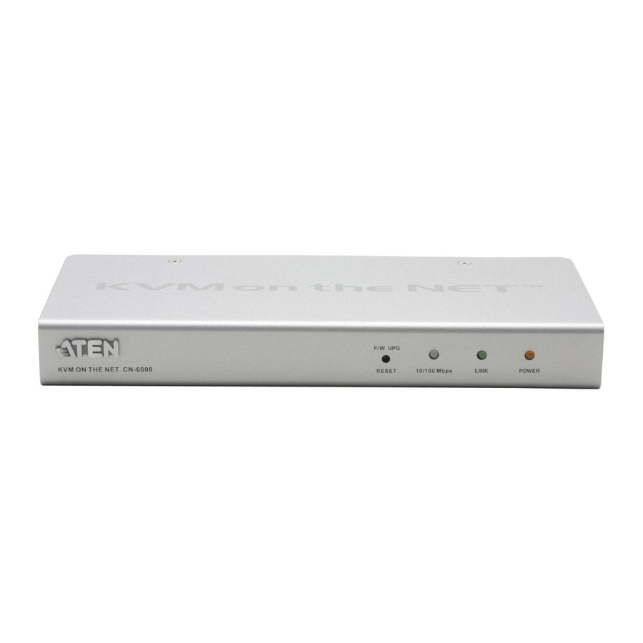
Front View 1. Reset / Firmware Upgrade Switch Pressing and holding this switch in while powering On the CN-6000 puts the switch into Firmware Upgrade mode. Pressing and holding this switch in for more that two seconds performs a system reset. -
Page 14: Rear View
KVM switch or server plugs in here. 2. Local Console Section The CN-6000 can be accessed via a local console as well as over the Net. The cables for the local console (keyboard, monitor, and mouse) plug in here. Each port is color coded and marked with an appropriate icon to indicate itself. -
Page 15: Installation
3. Plug the LAN or WAN cable into the CN-6000’s RJ-45 socket. 4. Plug the power adapter cable into the CN-6000’s power jack, then plug the power adapter into an AC power source. 5. Power up your server or KVM installation. - Page 16 CN-6000 User Manual Notes: 2003-11-03...
-
Page 17: The Administrator Utility
The Administrator Utility Chapter 3. The Administrator Utility Introduction Installation The Windows-based Administrator Utility software is provided on the distribution CD included with this package. To install the Administrator Utility, insert the CD into your CD-ROM drive and double click the CN6KAdmin... package icon. The Administration Utility installation screen appears: Follow the on-screen instructions. -
Page 18: Starting Up
If this is the first time that you are running the utility a dialog box appears requesting you to input your serial number. The serial number can be found on the bottom panel of the CN-6000. Key in the serial number - 5 characters per box - then Click OK. - Page 19 When the Utility comes back up, it searches for all the the CN-6000 devices installed on the local LAN segment and displays the results in the large central panel (CN-6000 devices). If the unit you wish to configure appears in the listbox, Double Click it.
-
Page 20: Logging In
CN-6000 User Manual Logging In Once the Administrator Utility connnects to the unit you specified, a login window appears: Only those who have Configuration privileges (see User Management; Permis- sions, p. 22) are allowed to log in. Provide a valid Username and Password, then Click Login to continue. - Page 21 The Administrator Utility If you successfully log in to the CN-6000 with the default username and password, the following message appears: For security purposes, be sure to change the default Username and Password to something unique (see User Management, p. 21).
-
Page 22: The Settings Notebook
Uploading Changes When the Settings have been configured to your satisfaction and you are ready to upload the changes to the CN-6000: 1. Click OK (at the bottom of the Settings notebook), to start the updating procedure.When updating has finished, the following message appears: 2. -
Page 23: General
Device Name: To make it easier to manage installations that have more than one CN-6000, each one can be given a name. To assign a name for the CN-6000, erase the current name and key in one of your choosing (15 characters max.). -
Page 24: Network
As a security measure, the Administrator can set the Port numbers that the User must specify when he attempts to connect to a CN-6000’s IP address. Unless the correct Port number is given, the CN-6000 device will not be found. An explana-... - Page 25 IP Address: The CN-6000 can either have its IP address assigned dynamically at bootup (DHCP), or it can be given a fixed IP address. For dynamic IP address assignment, select the Obtain an IP address automatically, radio button. To specify a fixed IP address: 1.
-
Page 26: Security
CN-6000 User Manual Security The Security page is used to control access to the CN-6000. User station filters permit or deny access to the CN-6000 for specific IP and MAC addresses attempting to access the system with CN-6000 Client software. - Page 27 Filtering: There are a maximum of 100 filters allowed for each category (User IPs, User MACs, and Administrator MACs). To enable filtering for User Stations, Click to put a check mark in the IP and/or MAC Filter enable checkbox. To add a filter, Click Add. A dialog box similar to the ones below appears (the top example is for IP address filters;...
- Page 28 If the include button is checked, all the addresses within the filter range are allowed access to the CN-6000; all other addresses are denied access. If the exclude button is checked, all the addresses within the filter range are denied access to the CN-6000;...
-
Page 29: User Management
User Management This page is used to manage user profiles. A maximum of 64 users can have access to a CN-6000. To add a user, Click Add and fill in the information asked for in the User Management dialog box that appears. (See p. 22.) To delete a user profile, select it and Click Remove. - Page 30 Additional information about the user that you may wish to include. Permissions By default, all users may access the CN-6000 via the Windows Client software. 1. Checking Configure defines an Administrator who is allowed to configure the system, but does not have permission to access the CN-6000 via the Java Client software.
-
Page 31: Customization
Working Modes If Stealth Mode is enabled, the CN-6000 cannot be pinged. If Echo Mode is disabled, the CN-6000 will not show up in the list of local CN-6000 units (see p. 10 and p. 30) Reset on exit Placing a check here causes the CN-6000 to reset itself and implement all the new changes when you Click OK. -
Page 32: Upgrading The Firmware And Java Program
CN-6000 User Manual Upgrading the Firmware and Java Program New versions of the Mainboard and Java Access Page firmware files can be downloaded from our website at http://xxxxx.com/downloads as they become available. To upgrade the firmware, do the following: 1. Go to the Customization page of the Administration configuration notebook (see p. - Page 33 Open. Go back and select the correct file type. 4. Enable the Reset on exit checkbox. 5. Click OK to save your settings and reset the CN-6000. Wait approximately 30 to 60 seconds before logging in to the Administrator Utility following the reset.
-
Page 34: Java Authentication Page
CN-6000 User Manual Java Authentication Page As an important security feature, users who connect to the CN-6000 via the Java Client must first log in before being allowed access. A Java Authentication Page that implements a Login (Username and Password) feature is provided on the distribution disk for this purpose. -
Page 35: Troubleshooting
After I move the This can happen if the new network supports DHCP but the CN-6000 to a different CN-6000 is configured to set the IP address manually, or if computer, it no longer the new network doesn’t use DHCP to assign IP... - Page 36 CN-6000 User Manual Notes: 2003-11-03...
-
Page 37: The Windows Client
If this is the first time that you are running the program, a dialog box appears requesting you to input your serial number: If you don’t know what it is, contact the CN-6000 administrator. Key in the serial number - 5 characters per box - then Click OK. -
Page 38: The Connection Screen
Double Click it. CN6000 IP: This area is used when you want to connect to a CN-6000 at a remote location. You can drop down the list box and select an IP address or key in an IP address if the one you want isn’t listed, then key in the Port number in the Port field. -
Page 39: Connecting
Remote View becomes active. Click it to connect and take over console control of the unit that is attached to the CN-6000. The screen ouput of the unit appears on your monitor. Your keystrokes and mouse movements are captured and sent to the CN-6000 to be executed on the attached unit. - Page 40 4. Once contact with the CN-6000 has been established, the Switch to Remote View button becomes active. Click it to connect to the CN-6000 and take over console control of the unit that is connected to it. Note: Before connecting to the CN-6000, you may want to set up your Hotkeys.
-
Page 41: Hotkeys
The Hotkey setup utility is accessed by opening the Tools menu (at the top of the Connection Screen, see p. 30) and selecting Hotkeys before connecting to the CN-6000. Note: If you forget what the hotkey combinations are after you have started your session, Click on the OSD Help button (see Screen Information, p. -
Page 42: Configuring The Hotkeys
CN-6000 User Manual An explanation of the actions is given in the table, below: Action Exit remote location Break the connection to the CN-6000 and return to local operation. Adjust Video Brings up the video adjustment utility. Adjust Mouse This utility synchronizes the local and remote mouse movements following a video resolution change. -
Page 43: Operation
Operation Screen Information Once the connection to the CN-6000 has been accomplished, the remote system’s video output is captured and displayed on your monitor. At the same time, your local keystroke and mouse input is captured and sent to the remote system. -
Page 44: Mouse Synchronization
CN-6000 User Manual Mouse Synchronization Until you close the CN-6000 connection, normal mouse functions are suspended on your local system. They are captured and sent to the remote system, instead. From time to time, especially if you change video resolution, the local mouse movement may lose synchronization with the remote system’s mouse pointer. - Page 45 If these procedures still do not help, set the mouse speed and acceleration for the computer (or computers via KVM switch) connected to the CN-6000 as follows: Windows 2000: Set the mouse speed to the middle position; set the mouse acceleration to None (Control Panel →...
-
Page 46: Video Adjustment
CN-6000 User Manual WinMe / Win95: Set the mouse speed to the middle position; disable mouse acceleration (click Advanced to get the dialog box for this). WinNT / Win98: Set the mouse speed to the slowest position. Video Adjustment You can adjust the placement and the picture quality of the remote screen (as displayed on your local monitor) with the Video Options function. - Page 47 An explanation of the settings is given in the following table: Screen Position Adjust the horizontal and vertical position of the remote display by Clicking the Arrow buttons. Auto-Sync Click Auto-Sync to have the function detect the vertical and horizontal offset values of the remote screen and automatically synchronize it with the local screen.
-
Page 48: Work Files
Work Files A Work File consists of all the information specified in a Client session. This includes the CN-6000 and CN-6000 IP list items, the Mouse Calibration settings, and the Hotkey and Video settings. Whenever a user runs the Client program, it opens with the values contained in the current work file. -
Page 49: Troubleshooting
DirectX installed, or another program is using it. Either install DirectX, or close the program that is already using it. The CN-6000 doesn’t The CN-6000’s default setting is to use port 9000 and port complete the login. 9001. This situation can occur if there is a firewall blocking these ports. - Page 50 CN-6000 User Manual Notes: 2003-11-03...
-
Page 51: The Java Client
The Java Client Introduction The Java Client is provided to make the CN-6000 accessible to all platforms and allows the User to connect from anywhere on the Internet. Any system that has Java 2 installed, can connect to the CN-6000. - Page 52 Key in the IP address for the unit you want to connect to - including a forward slash followed by the name of the CN-6000’s Java Client web page. For example: 168.10.95.001/cn6k.html Important! For security purposes, the name of the page that you connect to must be specified correctly as part of the IP address.
- Page 53 The Java Client After you establish a connection, a Login dialog box appears. Provide a valid Username and Password and Click OK. The Welcome Screen disappears and, after a second or two, a Login Progress window appears: 2003-11-03...
-
Page 54: The Main Screen
CN-6000 User Manual The Main Screen After a successful login, the remote system’s screen displays on your monitor as shown in the example below: You can perform mouse and keyboard operations on this screen just as if it were your local system’s display. -
Page 55: The User Panel
Keypad Some keyboard combinations can not be captured and sent to the CN-6000. In order to implement their effects on the remote system, this function provides a one-click implementation of some common window control combinations. - Page 56 CN-6000 User Manual Mouse Synchronization At times the local mouse movement may lose sync with the remote mouse movement. The Mouse Synchronization function gets them back into sync. This is similar to the Mouse Adjustment feature of the Windows Client (see p. 36 for details).
-
Page 57: Troubleshooting
CN-6000’s IP address. 2. Close the Java Client, reopen it, and try again. The CN-6000 doesn’t The CN-6000’s default setting is to use port 9000 and port complete the login. 9001. This situation can occur if there is a firewall blocking these ports. - Page 58 CN-6000 User Manual Notes: Notes: 2003-11-03...
-
Page 59: The Log Server
The Windows-based CN-6000 Log Server is an administrative utility that records all the events that take place on selected CN-6000 units and stores them in a searchable database. Installation Tthe Log Server is provided on the distribution CD included with this package. -
Page 60: Starting Up
The screen is divided into three components: A Menu Bar at the top A panel containing a list of CN-6000 units in the middle A panel containing an Events List at the bottom Each of the components is explained in the sections that follow. -
Page 61: The Menu Bar
CN-6000s from the list. To edit or delete a listed CN-6000, first select the one you want in the CN-6000 List window, then open this menu and click Edit or Delete. To add a CN-6000 to the CN-6000 List, click Add. -
Page 62: Events
A description of the fields is given in the table, below: Field Address This can either be the IP address of the CN-6000 or its DNS name (if the network administrator has assigned it a DNS name). Port The Port number assigned to the CN-6000 (see p. 16). - Page 63 CN-6000 List CN-6000 units are listed according to their IP address or DNS name. Select the unit that you want to perform the search on from this list. You can select more than one unit for the search.
-
Page 64: Options
CN-6000 User Manual Maintenance This function allows the administrator to perform manual maintenance of the database. He can use it to erase specified records before the expiration time that was set with the Limit setting of the Configure function (see p. 54) Options This menu has a single item: Retry. -
Page 65: The Cn-6000 List Panel
The CN-6000 List Panel Overview The CN-6000 List panel (refer back to the figure on p. 52), displays a list of all the CN-6000 units that have been selected for the Log Server to track (see Configure, p. 53). Tick information for the currently selected CN-6000 displays in the Events List panel below. -
Page 66: The Event List Window
CN-6000 User Manual The Event List Window This window displays tick information for the currently selected CN-6000. Note that even though any other CN-6000s aren’t currently selected, if their Recording checkbox is checked, the Log Server records their tick information and keeps it in its database. -
Page 67: Appendix
Specifications Specifications for the CN-6000 are given in the table, below: Function Connectors CPU Port 1 x SPDB-15 F - KVM Link Console 1 x 6 pin mini-DIN F - Keyboard Ports 1 x 6 pin mini-DIN F - Mouse... -
Page 68: Rack Mounting
CN-6000 User Manual Rack Mounting For convenience and flexibility, the CN-6000 can be mounted on a system rack. To rack mount the unit do the following: 1. Screw the mounting bracket into the top or bottom of the unit as shown in the example diagram below. - Page 69 Keypad 47 Login 45 Main Screen 46 Starting up 43 Troubleshooting 49 User Panel 47 Log Server 17 CN-6000 List Window 57 Configure 53 Event List Window 58 Events 54 Installation 51 Main Screen 52 Maintenance 55 Menu Bar 53...
- Page 70 CN-6000 User Guide Overview 1 Rack Mounting 60 Reset on exit 23 Serial number 10 Settings Notebook 14 General page 15 Network page 16 Security page 18 Uploading changes 14 Specifications 59 Substitute keys 35 System Requirements 3 Time out control 23...
Need help?
Do you have a question about the CN-6000 and is the answer not in the manual?
Questions and answers