ATEN PE4104AJ User Manual
Ip control box
Hide thumbs
Also See for PE4104AJ:
- User manual (92 pages) ,
- User manual (98 pages) ,
- User manual (104 pages)
Table of Contents
Advertisement
Quick Links
Advertisement
Table of Contents

Related Manuals for ATEN PE4104AJ


Summary of Contents for ATEN PE4104AJ
- Page 1 PE4104AJ / PE4104G IP Control Box User Manual...
-
Page 2: Compliance Statements
IP Control Box User Manual Compliance Statements FEDERAL COMMUNICATIONS COMMISSION INTERFERENCE STATEMENT This equipment has been tested and found to comply with the limits for a Class A digital device, pursuant to Part 15 of the FCC Rules. These limits are designed to provide reasonable protection against harmful interference when the equipment is operated in a commercial environment. - Page 3 IP Control Box User Manual Industry Canada Statement This Class A digital apparatus complies with Canadian ICES-003. VCCI Statement RoHS This product is RoHS compliant.
-
Page 4: User Information
Japan 81-3-5615-5811 Korea 82-2-467-6789 North America 1-888-999-ATEN ext 4988 1-949-428-1111 User Notice All information, documentation, and specifications contained in this manual are subject to change without prior notification by the manufacturer. The manufacturer makes no representations or warranties, either expressed or implied, with respect to the contents hereof and specifically disclaims any warranties as to merchantability or fitness for any particular purpose. -
Page 5: Product Information
For information about all ATEN products and how they can help you connect without limits, visit ATEN on the Web or contact an ATEN Authorized Reseller. Visit ATEN on the Web for a list of locations and telephone numbers: International http://www.aten.com... -
Page 6: Table Of Contents
IP Control Box User Manual Contents Compliance Statements ........ii User Information . - Page 7 IP Control Box User Manual Browser Operation Chapter 4. Logging In ..........15 The eco PDU Main Page .
- Page 8 PE4104AJ ........
-
Page 9: About This Manual
Read this manual thoroughly and follow the installation and operation procedures carefully to prevent any damage to the unit and/or connected devices. The product may be updated, with features and functions added, improved, or removed since the release of this manual. For an up-to-date user manual, visit http://www.aten.com/global/en/. -
Page 10: Conventions
IP Control Box User Manual Conventions This manual uses the following conventions: Monospaced Indicates text that you should key in. Indicates keys you should press. For example, [Enter] means to press the Enter key. If keys need to be chorded, they appear together in the same bracket with a plus sign between them: [Ctrl+Alt]. -
Page 11: Chapter 1 Introduction
Chapter 1 Introduction Overview Engineered to be an intelligent power distribution solution, the IP Control Box ships with 4 power outlets in an IEC or NEMA socket configuration. It provides secure, centralized, intelligent, and remote power management of data center IT equipment to minimize the operating cost. The IP Control Box features remote power control function, allowing you to control devices attached to the PDU at the PDU device level from practically any location via a TCP/IP connection. -
Page 12: Features
Space saving slim form factor IEC power outlet (applicable to PE4104G only) NEMA outlet (applicable to PE4104AJ only) Separates power for the unit’s own power and its power outlets – user interface is still accessible even when an overload condition trips the device’s circuit breaker... -
Page 13: Requirements
Chapter 1. Introduction Requirements Browsers accessing the IP Control Boxunit must support 2048 and 4096 bit encryption. For cold booting of attached computers, the computer’s BIOS must support wake on LAN or System after AC Back. For Safe Shutdown: The computer must be running Windows (Windows 2000 or higher) or Linux. -
Page 14: Optional Accessories
Plug cable holders to secure the cables from your attached devices in place on the eco PDU unit. Use only the ATEN Lok-U-Plug cable holders that have been specifically designed to work with the eco PDU. Using any other kind of cable securing device could be highly dangerous. -
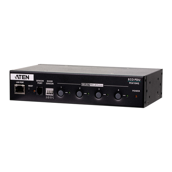
Page 15: Components
Electrical appliances plug in here. sockets circuit breaker Protects the PDU from damage caused by excess current from an overload or short circuit. power inlet The power cord of the package content plugs in here. power cable Power cord (attached) for the PE4104AJ. - Page 16 IP Control Box User Manual This Page Intentionally Left Blank...
-
Page 17: Chapter 2. Hardware Setup
Chapter 2 Hardware Setup Important safety information regarding the placement of this device is provided on page 63. Please review it before proceeding. Rack Mounting The IP Control Box can be mounted vertically on the outside of the rack and a few options are available. - Page 18 IP Control Box User Manual 2. Align and stabilize the rack mount ear using M3 Phillips hex screws. 3. Align the unit and the rack mount ear to the rack and stabilize the unit using rack screws. Let the buttons stabilize in the button holes and the mounting is complete.
-
Page 19: Installation
Chapter 2. Hardware Setup Installation To set up your IP Control Box installation, refer to the installation diagram and the procedure below. The PE4104AJ is used as an example to illustrate the installation. Power e.g. Humidity Sensor Ethernet Network e.g. Door Sensor 1. -
Page 20: Securing The Cable
7. Power on the connected devices. Securing the Cable For added safety, use ATEN Lok-U-Plug cable holders to secure the cables from your attached devices in place onto the IP Control Box. Secure the cable holders using the specially designed holes around the individual power outlets,... -
Page 21: Chapter 3. Basic Operation And First Time Setup
Graphical Interface that allows you to configure a PDU device and monitor power status of the equipment connected to it. eco DC Energy Management Software can be downloaded from the ATEN website, along with a separate eco DC User Manual. -
Page 22: First Time Setup
IP Control Box User Manual First Time Setup Once the eco PDU installation has been cabled up, the next task the Administrator needs to perform involve configuring the network parameters, changing the default Super Administrator login settings, and adding users. The way to accomplish this is to log in via web browser. -
Page 23: Network Configuration
Chapter 3. Basic Operation and First Time Setup Network Configuration To configure the network settings, do the following: 1. Click the Setup tab. 2. The interface displays the Device Configuration page. A screen similar to the one below appears: 3. Fill in the fields according to the information provided under Device Configuration, page 30. -
Page 24: Moving On
IP Control Box User Manual Moving On After setting up the network and changing the default Administrator username and password, you can proceed to other administration activities – including adding users. This is covered in the next chapter. -
Page 25: Chapter 4. Browser Operation
Chapter 4 Browser Operation Logging In The IP Control Box can be accessed via a supported Internet browser from any platform. Note: Browsers must support SSL 2048 and 4096 bit encryption. To access the IP Control Box do the following: 1. - Page 26 IP Control Box User Manual 3. Provide a valid Username and Password (set by the administrator), and select your language. (Options are: English [default]; Traditional Chinese; Simplified Chinese; Japanese; German; Italian; Spanish; French; Russian; Korean; Portuguese). 4. Then Click Login to bring up the browser Main Page.
-
Page 27: The Eco Pdu Main Page
The Sidebar provides a tree view listing of outlets that relate to the various tab bar and menu bar selections. Help Connects to on-line help at the ATEN website for the device’s configuration and operation. Logout Click this button to log out of your IP Control Box session. -
Page 28: Energy
IP Control Box User Manual Energy Connections When you log in to the IP Control Box, the interface opens with its default selection of the Energy tab; and the Connections menu. The contents of the PDU Status, Sensor Status, and Outlet Status sections are displayed in the main panel. -
Page 29: Sensor Status
Chapter 4. Browser Operation On / Off / Reboot You can manually turn the device On and Off from this page by clicking the radio buttons. To Reboot the device, enable the Reboot checkbox and click on Save (located at the bottom of the page). Sensor Status If you have sensors installed in your installation, use these fields to set the maximum, minimum and fluctuation threshold settings for Temperature,... -
Page 30: Configuration
IP Control Box User Manual Configuration The Configuration page is used to configure the settings of the IP Control Box at the individual power outlet level. Power On Time Schedule Settings Check the Enable Power On Time Schedule box to use the Power ON Delay setting to set the amount of time the eco PDU waits before powering on an outlet. - Page 31 Chapter 4. Browser Operation Control/Display Description Outlet Shows the port number of the listed outlet. Outlet Name Each outlet can be given a distinctive name. The maximum number of characters is 48. Confirmation If this option is enabled (there is a check in the checkbox), a Required dialog box comes up asking you to confirm a power operation before it is performed.
- Page 32 IP Control Box User Manual Control/Display Description Remote Turn ON Use the drop-down menu to select one of the choices, below: Method Wake on LAN This is a Safe Shutdown and Restart option. If this is selected, when an Outlet is turned Off, the eco PDU first sends a message to the computer telling it to prepare for a shutdown;...
- Page 33 Chapter 4. Browser Operation Control/Display Description Auto Ping Method Auto Ping Method defines the mechanism which the IP Control Box uses to ping a device and to reboot the outlet. To enable this setting, check the Enable checkbox, or check the Disable checkbox to disable.
-
Page 34: User
IP Control Box User Manual User When you select the User tab the screen comes up with Administrator Information and User Information displayed in the main panel. The IP Control Box supports one Administrator account and up to eight User accounts. Note: 1. -
Page 35: Snmpv1/V2C Community
Chapter 4. Browser Operation SNMPv1/v2c Community Enter values Read community and Write community for SNMPv1/V2c authentication, if required. Telnet Use the Name and Password fields to change the account used to login via Telnet sessions. Enter values in the required fields to change the account used to login via SSH. - Page 36 IP Control Box User Manual Field Description Name From 1 to 16 characters are allowed depending on the Account Policy settings. See Account Policy, page 39. Password From 1 to 16 characters are allowed depending on the Account Policy settings. See Account Policy, page 39. Outlet This field allows you to set the outlet-by-outlet permissions of the user.
-
Page 37: Log
Chapter 4. Browser Operation The Log tab keeps a record of transactions that take place on its installation, and stores up to 1024 events at one time. The System Log page provides a powerful array of filters and functions that allow you to view and export the log file data, as well as be informed by email of specified events as they occur. -
Page 38: Notification Settings
IP Control Box User Manual Notification Settings The Notification Settings page is used to specify which of the IP Control Box’s components will receive notification of a log event. When you click the Notification Settings menu item, a page similar to the one below appears: The event categories are listed in the left column. - Page 39 Chapter 4. Browser Operation If you only want to set notification for some of the sub-category events, don’t put a check in the main category row. Instead, drop down the sub-category list, and only check the sub-category events you want. When you have finished making your setting choices, click Save.
-
Page 40: Setup
Firmware Version This item displays the current firmware version number. You can reference it to see if there are newer versions available on the ATEN website. Rack Location This field lets you give the rack location a unique name for easy Name reference. -
Page 41: Service Ports
Chapter 4. Browser Operation Service Ports As a security measure, if a firewall is being used, the Administrator can specify the port numbers that the firewall will allow. If a port other than the default is used, users must specify the port number as part of the IP address when they log in. -
Page 42: Ipv4 Configuration
IP Control Box User Manual IPv4 Configuration The PDU’s IPv4 IP and DNS addresses (the traditional method of specifying IP addresses) can either be assigned dynamically (DHCP), or a fixed IP address can be specified. For dynamic IP address assignment, select the Obtain IP address automatically radio button. -
Page 43: Event Notification
Chapter 4. Browser Operation obtained the address after one minute, it automatically reverts to its factory default IP address (192.168.0.60.) 2. If the device is on a network that uses DHCP to assign network addresses, and you need to ascertain its IP address, see IP Address Determination, page 67, for information. - Page 44 IP Control Box User Manual Note: If you are sending the report to more than one email address, separate the addresses with a semicolon. The total cannot exceed 256 characters. SNMP Trap Receivers Up to four SNMP management stations can be specified. If you want to use SNMP trap notifications, do the following: 1.
- Page 45 Chapter 4. Browser Operation Note: Make sure that the port number you specify here matches the port number used by the SNMP receiver computer. 4. Key in the community value(s) if required for the SNMP version. 5. Key in the auth/privacy password(s) that correspond to each of the stations.
-
Page 46: Date/Time
IP Control Box User Manual Date/Time The Date/Time dialog page sets the IP Control Box time parameters: Time Zone To establish the time zone that the IP Control Box is located in, drop down the Time Zone list and choose the city that most closely corresponds to where it is at. -
Page 47: Finishing Up
Chapter 4. Browser Operation As an alternative to specifying the date and time by entering them into the date and time fields, you can click to put a check in the Sync with PC checkbox, in which case the eco PDU will take its date and time settings from the locally connected PC. -
Page 48: Security
IP Control Box User Manual Security The Security page controls access to the IP Control Box device. -
Page 49: Working Mode
Chapter 4. Browser Operation Working Mode If Enable Telnet Server is checked, the PDU is accessible via a Telnet sessions using the Telnet username and password (see Telnet, page 25) If Enable Modbus is checked, the PDU is accessible and the measurements of the PDU such as current, voltage, power, temperature, humidity, and pressure can be read via the Modbus communications protocol. -
Page 50: Ip Filter / Mac Filter
IP Control Box User Manual Check a policy and enter the required information in the appropriate fields. Item Description Minimum Username Length Sets the minimum number of characters required for a username. Acceptable values are from 1–16. Minimum Password Length Sets the minimum number of characters required for a password. - Page 51 Chapter 4. Browser Operation If the exclude button is checked, all the addresses within the filter range are denied access; all other addresses are allowed access. Adding Filters To add an IP filter, do the following: 1. Click Add. A dialog box similar to the one below appears:...
- Page 52 IP Control Box User Manual 2. Specify the start filter address in the dialog box (for example, 192.168.0.200), then click OK. 3. To filter a single IP address, key in the same address as the start IP. To filter a continuous range of addresses, key in the end number of the range (for example, 192.168.0.225).
-
Page 53: Authentication & Authorization
Chapter 4. Browser Operation Authentication & Authorization The Authentication & Authorization page is used to set up login authentication and authorization management from external sources. RADIUS Settings To allow authentication and authorization for the eco PDU device through a RADIUS server, do the following: 1. -
Page 54: Private Certificate
For enhanced security, the Private Certificate section allows you to use your own private encryption key and signed certificate, rather than the default ATEN certificate. There are two methods for establishing your private certificate: generating a self-signed certificate;... -
Page 55: Ecotcp
3. Click Upload to complete the procedure. Note: 1. Clicking Restore Default returns the device to using the default ATEN certificate. 2. Both the private encryption key and the signed certificate must be imported at the same time. -
Page 56: Scheduler
IP Control Box User Manual Scheduler Use the Scheduler page to power on, power off, or reboot the IP Control Box. To create an event, follow the steps below. 1. Go to Setup > Scheduler. 2. Create one or more power-on, power-off, and/or reboot actions. These actions will be selectable when configuring an event. - Page 57 Chapter 4. Browser Operation c) Click Save. The action is added to the list. 3. Create an event. a) Click +Create Event. b) In the pop-up screen, name the event, and then configure the schedule and action as needed. c) Click Save. The event is added to the event list. Use the toggle button to enable/disable created events.
-
Page 58: Pdu
IP Control Box User Manual The PDU tab is used to upgrade the PE4104G’s firmware, and to backup and restore the device’s configuration settings. Upgrade Main Firmware The Upgrade Main Firmware page is used to upgrade the firmware of the IP Control Box. - Page 59 Chapter 4. Browser Operation 2. Click the Browse button; navigate to where the firmware file is located and select it. 3. Click Upgrade to start the upgrade procedure. If you enabled Check Main Firmware Version the current firmware level is compared with that of the upgrade file. If the current version is equal to or higher than the upgrade version, a popup message appears, to inform you of the situation and stops the upgrade procedure.
-
Page 60: Backup/Restore
IP Control Box User Manual Backup/Restore Selecting Backup/Restore on the menu bar gives you the ability to back up the switch’s configuration and user profile information: Station List Station List lists the IP Control Box only. Backup To backup the device’s settings do the following: 1. -
Page 61: Restore
Chapter 4. Browser Operation Restore To restore a previous backup, do the following: 1. Click Browse; navigate to the file and select it. Note: If you renamed the file, you can leave the new name. There is no need to return it to its original name. 2. - Page 62 IP Control Box User Manual This Page Intentionally Left Blank...
-
Page 63: Chapter 5. Telnet Commands
Chapter 5 Telnet Commands Remote Terminal Operations With ATEN IP Control Box you can log in remotely from a computer using Telnet interface that allows system control through a high-end controller or PC. Telnet Telnet is a program that connects to a device over a network to provide text- based management and control. -
Page 64: Session Timeout
IP Control Box User Manual Click OK. 2. At the command prompt, key in telnet and the IP Address of the PDU, as follows: telnet [IP Address] 3. Press Enter. The login screen appears: 4. At the login prompt, enter Username: teladmin; and Password: telpwd. Note: The Telnet username and password can be configured on the User tab of the IP Control Box's web GUI. -
Page 65: Commands
Chapter 5. Telnet Commands Commands Use the Telnet commands to view and configure the IP Control Box as described in each section. The text-based command line provides some of the same functions found under the Energy tab of the IP Control Box’s web-based GUI. -
Page 66: Read Power Outlet Status
IP Control Box User Manual Read Outlet Status Power The Read Power Outlet Status command allows you to view the power status of an outlet on the IP Control Box. The formula for Read Outlet Status commands is as follows: Command + Outlet + Number + Option + [Enter] 1. -
Page 67: Switch Outlet Status
Chapter 5. Telnet Commands Switch Outlet Status The Switch Outlet Status command allows you to change the power status of an outlet on the IP Control Box. The formula for Switch Outlet Status commands is as follows: Command + Outlet + Number + Option + Control + [Enter] 1. - Page 68 IP Control Box User Manual The following table lists the available Switch Outlet Status commands: Command Outlet Option Control Enter Description imme [Enter] Switch outlet XX on with option imme or delay. XX: delay Outlet number (01 ~ 04) imme [Enter] Switch outlet XX off with option imme or delay.
-
Page 69: Read Environmental Value
Chapter 5. Telnet Commands Read Environmental Value The Read Environmental Value command allows you to view measurements from the IP Control Box’s environmental sensors. The formula for Read Environmental Value commands is as follows: Command + Outlet + Number + Option + [Enter] 1. -
Page 70: Close Telnet Session
IP Control Box User Manual The following table lists the available Read Environmental Value commands: Command Sensor Option Enter Description read sensor simple [Enter] Read the environmental sensor value on the selected power outlet with format environmental sensor installed. Outlet XX with option simple or format. -
Page 71: Reboot Pdu Device
Chapter 5. Telnet Commands Reboot PDU Device The Reboot PDU Device command allows you to reboot the IP Control Box. The formula for Reboot PDU Device commands is as follows: Command + [Enter] 1. For example, if you want to reboot the IP Control Box, type the following: reboot [Enter] The following tables show the possible values for the Read Environmental Value commands:... - Page 72 IP Control Box User Manual The following table lists the available Reset All PDU Config to Default Value command: Command Enter Description clearallsetting [Enter] IP Control Box Resets the to default factory settings.
-
Page 73: Appendix
Appendix Safety Instructions General This product is for indoor use only. Read all of these instructions. Save them for future reference. Follow all warnings and instructions marked on the device. Do not place the device on any unstable surface (cart, stand, table, etc.). If the device falls, serious damage will result. - Page 74 IP Control Box User Manual If an extension cord is used with this device make sure that the total of the ampere ratings of all products used on this cord does not exceed the extension cord ampere rating. Make sure that the total of all products plugged into the wall outlet does not exceed 15 amperes.
-
Page 75: Rack Mounting
Appendix Rack Mounting Before working on the rack, make sure that the stabilizers are secured to the rack, extended to the floor, and that the full weight of the rack rests on the floor. Install front and side stabilizers on a single rack or front stabilizers for joined multiple racks before working on the rack. -
Page 76: Administrator Login Failure
IP Control Box User Manual Administrator Login Failure If you are unable to perform an Administrator login (because the Username and Password information has become corrupted, or you have forgotten it, for example), you can clear the login information with the following procedure: 1. -
Page 77: Ip Address Determination
Appendix IP Address Determination If you are an administrator logging in for the first time, you need to access the eco PDU in order to give it an IP address that users can connect to. There are two methods to choose from. In each case, your client computer must be on the same network segment as the eco PDU. -
Page 78: Method 2
DC allows you to determine/assign an IP address in order to configure a PDU device and monitor power status of the equipment connected to it. eco DC can be obtained from the Download area of the ATEN web site. -
Page 79: Technical Support
Appendix Technical Support International For online technical support – including troubleshooting, documentation, and software updates: http://support.aten.com For telephone support, see Telephone Support, page iv North America Email Support support@aten-usa.com Online Troubleshooting http://www.aten-usa.com/support Technical Documentation Support Software Updates Telephone Support 1-888-999-ATEN ext 4988... -
Page 80: Specifications
IP Control Box User Manual Specifications PE4104AJ Outlet 4 x NEMA 5 - 15P Inlet LAN Port 1 x RJ-45 Female with LEDs (Silver / LED: Orange / Green) 10/100M Outlet 4 x Green Power 1 x Orange Sensor 1 x Orange... - Page 81 Appendix Power Cord Length 1.8 m Environmental Temperature (Operating / Storage) 0–50ºC / –20–60ºC Humidity (Operating / Storage) 0–80ºC RH, Non-Condensing Compliance EMC Verification Safety Verification...
-
Page 82: Pe4104G
IP Control Box User Manual PE4104G Outlet 4 x IEC C13 Inlet IEC C14 LAN Port 1 x RJ-45 Female with LEDs (Silver / LED: Orange / Green) 10/100M Outlet 4 x Green Power 1 x Orange Sensor 1 x Orange Buttons Reset 1 x Semi-recessed Pushbutton... - Page 83 Appendix Environmental Temperature (Operating / Storage) 0–50ºC / –20–60ºC Humidity (Operating / Storage) 0–80ºC RH, Non-Condensing Compliance EMC Verification CE-EMC Safety Verification CE-LVD...
-
Page 84: Limited Warranty
© Copyright 2022 ATEN® International Co., Ltd. Released: 2022-08-17 ATEN and the ATEN logo are registered trademarks of ATEN International Co., Ltd. All rights reserved. All other brand names and trademarks are the registered property of their respective owners.
Need help?
Do you have a question about the PE4104AJ and is the answer not in the manual?
Questions and answers