Table of Contents
Advertisement
Quick Links
Specifications
Wingspan:
Length:
Weight with Battery:
Battery:
Charger:
Transmitter:
On‐Board Electronics:
12.4 in (315mm)
10.6 in (270mm)
0.3 oz (9g)
30mAh 1S 3.7V LiPo (included)
1S 3.7V LiPo (in transmitter, included)
3‐channel 2.4GHz w/LiPo charger (included)
2‐in‐1 receiver/ESC and magnetic actuator (installed)
Instruction Manual
1
Advertisement
Table of Contents

Related Manuals for Ares Nano-Micro Stick 75


Summary of Contents for Ares Nano-Micro Stick 75
-
Page 1: Instruction Manual
Instruction Manual Specifications Wingspan: 12.4 in (315mm) Length: 10.6 in (270mm) Weight with Battery: 0.3 oz (9g) Battery: 30mAh 1S 3.7V LiPo (included) Charger: 1S 3.7V LiPo (in transmitter, included) Transmitter: ... -
Page 2: Table Of Contents
Table of Contents Specifications .......................... 1 Introduction .......................... 3 Safety Precautions and Warnings .................... 3 FCC Information ......................... 4 Nano‐Micro Stick 75 RTF Contents ..................... 5 Before the First Flight Checklist .................... 6 Flight Checklist ........................... 6 Installing the Transmitter Batteries ................... 7 Transmitter Details ........................ 7 LiPo Battery Warnings and Usage Guidelines ................ 8 Charging the LiPo Flight Battery .................... 10 Installing the LiPo Flight Battery .................... 12 Control Unit Initialization and Arming .................. 13 Flight Controls and Trimming .................... 16 Selecting a Flying Area ...................... 18 Flying ............................ 18 Adjusting the Wing Position and Center of Gravity .............. 20 Transmitter and Receiver Binding/Linking ................ 21 Repairs ............................. 22 Replacement Parts List ...................... 22 Warranty, Support and Service .................... 23 ... -
Page 3: Introduction
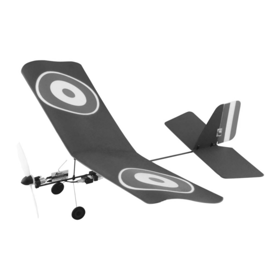
Introduction Weighing in at only 9 grams ready to fly – about 1/4 the weight of typical ultra‐micro class models – the Ares™ [air‐eez] Nano‐Micro Stick 75 is a great choice when looking for a lightweight airplane to fly indoors in more places than ever before. The nano‐micro size and weight allows for slow and easy flying even in smaller indoors spaces from a great room at home to a conference room at the office. Plus, the proportional throttle and rudder controls make it easy for almost anyone to fly while offering plenty of maneuverability and control for experienced pilots too. The Nano‐Micro Stick 75’s classic stick‐style design is available in two popular WWI‐era trim schemes so you can fly in squadrons or simulate dogfights with friends. And the durable, lightweight construction means you don’t always have to worry about damage after less than perfect missions or landings. Best of all, the airframe is 100% factory‐assembled and ready‐ to‐fly right out of the box – no tools required! Also in the box is everything needed to fly including AA batteries for the 3‐channel transmitter equipped with interference‐free 2.4GHz technology, digital trims and a built‐in LiPo battery charger. And the included 30mAh 1S 3.7V LiPo battery delivers plenty of power and long flight times per charge. That means there’s nothing extra to buy and you can be ready to fly within minutes of opening the box. And although the Ultra‐Micro Trainer 100 is ready‐to‐fly right out the box, please take the time to read through this manual for more information about battery safety and charging, control checks and more before making your first flight. Please also visit our web site at www.Ares‐RC.com for additional information including product updates, bulletins, videos and more. Safety Precautions and Warnings Failure to use this product in the intended manner as described in the following instructions can result in damage and/or personal injury. An RC airplane is not a toy! If misused it can cause serious bodily harm and damage to property. ... -
Page 4: Fcc Information
As the user of this product you are solely and wholly responsible for operating it in a manner that does not endanger yourself and others or result in damage to the product or the property of others. This model is controlled by a radio signal that is subject to possible interference from a variety of sources outside your control. This interference can cause momentary loss of control so it is advisable to always keep a safe distance from objects and people in all directions around your model as this will help to avoid collisions and/or injury. • Never operate your model if the voltage of the batteries in the transmitter is too low. • Always operate your model in an open area away from obstacles, people, vehicles, buildings, etc. • Carefully follow the directions and warnings for this and any optional support equipment (chargers, rechargeable batteries, etc.). • Keep all chemicals, small parts and all electronic components out of the reach of children. • Moisture causes damage to electronic components. Avoid water exposure to all electronic components, parts, etc. not specifically designed and protected for use in water. • Never lick or place any portion of your model in your mouth as it could cause serious injury or even death. FCC Information This device complies with part 15 of the FCC rules. Operation is subject to the following two conditions: (1) This device may not cause harmful interference, and (2) this device must accept any interference received, including interference that may cause undesired operation. Caution: Changes or modifications not expressly approved by the party responsible for compliance could void the user’s authority to operate the equipment. This product contains a radio transmitter with wireless technology which has been tested and ... -
Page 5: Nano-Micro Stick 75 Rtf Contents
Nano-Micro Stick 75 RTF Contents Item Description Not Available Separately . Nano‐Micro Stick 75 RTF Airframe AZS1158AMD2 .... M3LPA‐100C Micro 3‐Channel LP Airplane Transmitter w/100mA Charger, Mode 2 Not Available Separately . 4 AA Batteries AZSB301S10UM .... 30mAh 1‐Cell/1S 3.7V 10C LiPo Battery, Ultra‐Micro Connector 5 ... -
Page 6: Before The First Flight Checklist
Before the First Flight Checklist PLEASE NOTE: This checklist is NOT intended to replace the content included in this instruction manual. Although it can be used as a quick start guide, we strongly suggest reading through this manual completely before proceeding. Remove and inspect all contents Install the four AA batteries in the transmitter Begin charging the flight battery (connect it to the charger in the transmitter) Install the flight battery in the airplane (after it’s been fully charged) Test the controls to confirm proper operation Familiarize yourself with the controls Find a suitable area for flying Flight Checklist PLEASE NOTE: This checklist is NOT intended to replace the content included in this instruction manual. Although it can be used as a quick start guide, we strongly suggest reading through this manual completely before proceeding. Always turn the transmitter on first Plug the flight battery into the control unit Allow the control unit to initialize and arm properly ... -
Page 7: Installing The Transmitter Batteries
Installing the Transmitter Batteries Install the four included AA batteries in the back of the transmitter by first removing the battery compartment cover/door. Ensure proper polarity of the batteries before installing them as noted by the markings molded into the battery compartment, then re‐install the compartment cover/door. Check for proper operation of the transmitter by switching the power switch on (slide it to the right). You should hear three beeps/tones from the transmitter while the ‘POWER’ LED indicator begins to glow solid red. This indicates the transmitter is powered on and the AA batteries are installed correctly. Transmitter Details The Nano‐Micro Stick 75 RTF includes an M3LPA‐100C Micro 3‐Channel LP Airplane transmitter equipped with interference‐free 2.4GHz FHSS technology, digital trims and a built‐in 1‐cell/1S 3.7V, 100mA LiPo battery charger. 7 ... -
Page 8: Lipo Battery Warnings And Usage Guidelines
When the transmitter is powered on, and whether or not a LiPo battery is being charged, there will be a constant beep/tone until the AA batteries are replaced. Antenna Position/Orientation The RF output signals transmit best/strongest from the shaft of the antenna rather than from the tip. As a result you should never point the tip of the antenna directly at the model. Also, the transmitter antenna can be rotated and folded up to 90° so be sure to hold the transmitter and position the antenna as needed to ensure the best possible signal transmission. LiPo Battery Warnings and Usage Guidelines IMPORTANT NOTE: Lithium Polymer (LiPo) batteries are significantly more volatile than the alkaline, NiCd and NiMH batteries also used in RC applications. All instructions and warnings must be followed exactly to prevent property damage and/or personal injury as mishandling of LiPo batteries can result in fire. By handling, charging or using the included LiPo battery you assume all risks associated with LiPo batteries. If you do not agree with these conditions, please return your complete product in new, unused condition to the place of purchase immediately. And although the 30mAh 1‐Cell/1S 3.7V 10C LiPo Battery (AZSB301S10UM) included with your Ares™ Nano‐Micro Stick 75 RTF is intended to be charged safely using the LiPo battery charger built into the included M3LPA‐100C Micro 3‐Channel LP Airplane Transmitter w/100mA Charger (AZS1158AMD2), you must read the following safety instructions and warnings before handling, charging or using the LiPo battery. • You must charge the LiPo battery in a safe area away from flammable materials. • Never charge the LiPo battery unattended at any time. When charging the battery you should always remain in constant observation to monitor the charging process and react immediately to any potential problems that may occur. 8 ... - Page 9 • After flying/discharging the battery you must allow it to cool to ambient/room temperature before recharging. • To charge the battery you must use only the LiPo battery charger built into the included M3LPA‐100C Micro 3‐Channel LP Airplane Transmitter w/100mA Charger (AZS1158AMD2) or a suitably compatible LiPo battery charger. Failure to do so may result in a fire causing property damage and/or personal injury. DO NOT use a NiCd or NiMH charger. • If at any time during the charge or discharge process the battery begins to balloon or swell, discontinue charging or discharging immediately. Quickly and safely disconnect the battery, then place it in a safe, open area away from flammable materials to observe it for at least 15 minutes. Continuing to charge or discharge a battery that has begun to balloon or swell can result in a fire. A battery that has ballooned or swollen even a small amount must be removed from service completely. • Store the battery partially charged (approximately 50% charged/3.85V per cell), at room temperature (approximately 68–77° Fahrenheit [F]) and in a dry area for best results. • When transporting or temporarily storing the battery, the temperature range should be from approximately 40–100°F. Do not store the battery or model in a hot garage, car or direct sunlight whenever possible. If stored in a hot garage or car the battery can be damaged or even catch fire. • Do not over‐discharge the LiPo flight battery. Discharging the LiPo flight battery to a voltage that is too low can cause damage to the battery resulting in reduced power, flight duration or failure of the battery entirely. LiPo cells should not be discharged to below 3.0V each under load. In the case of the 1‐Cell/1S 3.7V LiPo battery used to power the Nano‐Micro Stick 75 you will not want to allow the battery to fall below 3.0V during flight. The 2‐in‐1 control unit features a soft low voltage cutoff (LVC) that smoothly reduces power to the motor/power system (regardless of the power level you have set with the left‐hand/throttle stick) to let you know the voltage of the battery is close to the 3.0V minimum. However, even before this reduction in power, if you find that more ...
-
Page 10: Charging The Lipo Flight Battery
which may cause permanent damage to the LiPo battery resulting in lost power and flight duration during subsequent fights (or failure of the battery entirely). Also, it is not recommended that you fly to the soft LVC every time you fly. Instead you should be aware of the power level of the battery/airplane throughout the flight, and if at any time the airplane begins to require more throttle/power than typical to maintain cruise or climb, you should land the airplane and disconnect the LiPo battery immediately. Constantly discharging the battery to the soft LVC can still cause permanent damage to the battery so it’s best to use a timer or stop‐watch to time the duration of your flights and to stop flying at a reasonable time before the soft LVC is reached. Charging the LiPo Flight Battery You must charge the included 30mAh 1‐Cell/1S 3.7V 10C LiPo Battery (AZSB301S10UM) using the LiPo battery charger built into the included M3LPA‐100C Micro 3‐Channel LP Airplane Transmitter w/100mA Charger (AZS1158AMD2) or a suitably compatible LiPo battery charger. Charging the LiPo battery using a non‐LiPo battery compatible charger (such as a NiCd or NiMH battery charger), or even a different LiPo battery charger with the incorrect settings, may result in damage to the battery or even fire resulting in property damage and/or personal injury. Please follow these steps to charge the LiPo battery with the transmitter’s built‐in charger: Carefully open the small hatch located on the left side of the transmitter near the bottom left corner and extend the charge lead outside of the transmitter case. You can leave the hatch open or close it by routing the charge lead through the small cutout/opening in the hatch door. Connect the battery to the connector at the end of the charge lead extending from the transmitter. YOU MUST BE CAREFUL TO ENSURE PROPER POLARITY BEFORE MAKING THE CONNECTION by aligning the small red circle marking on the housing of the battery with the small red circle marking on the charge lead connector. While the ... - Page 11 When the battery is connected to the charge lead securely and with the proper polarity the ‘CHG (charge)’ LED indicator on the transmitter will glow solid yellow. The battery will be charging anytime the LED indicator is glowing solid yellow and whether or not the transmitter is powered on. It will take approximately 25‐40 minutes to charge a fully discharged (not over‐ discharged) battery. And when the battery is fully charged the LED indicator will stop glowing yellow entirely. When the LED indicator is no longer glowing you can remove the battery from the charger as it is now fully charged and ready for use. NOTE: The LiPo battery included with your new model will arrive partially charged. For this reason the initial charge may only take approximately 15‐20 minutes. NOTE: It’s safer and better for the longevity of the battery to store it only partially charged for any length of time. Storing the battery at approximately 50% charged (which is approximately 3.85V per cell) is typically best, however, it will take some careful management of the charge time and the use of a volt meter to achieve this voltage. If you have the equipment and skills to achieve the 50% charge level for storage it is recommended. If not, simply be sure to not store the battery fully charged whenever possible. In fact, as long as the battery will be stored at approximately room temperature and for no more than a few weeks before the next use, it may be best to store the battery in the discharged state after the last flight (as long as the battery was not over‐discharged on the last flight). 11 ...
-
Page 12: Installing The Lipo Flight Battery
Installing the LiPo Flight Battery NOTE: You must ALWAYS turn the transmitter on first, BEFORE connecting/installing the LiPo flight battery. And before proceeding with the following steps, please be sure the transmitter is powered on. After the LiPo battery has been fully charged it’s ready to be installed in the airplane. However, the first step before installing the battery is to connect it to the 2‐in‐1 control unit. ALSO, YOU MUST BE CAREFUL TO ENSURE PROPER POLARITY BEFORE CONNECTING THE BATTERY TO THE 2‐IN‐1 CONTROL UNIT CONNECTOR. By orienting/aligning the small red circle marking on the housing of the battery with the small red circle marking on the connector for the 2‐in‐1 control unit you’ll be able to make the connection with the correct polarity. Also, although the white connectors are ‘keyed’ to minimize the risk of a reverse polarity connection, if you force them it is possible to make connection with the incorrect polarity potentially causing damage to the 2‐in‐1 control unit and/or battery. When the red circle markings are properly aligned for correct polarity, connecting the white connectors should require only a minimal amount of pressure to achieve the light ‘click’ that indicates secure connection. After the LiPo battery is connected to the 2‐in‐1 control unit the unique magnetic attachment design makes it quick and easy to install the battery. Simply place the side of the battery with the magnetic attachment against the magnet located in the battery support and the battery will be mounted securely in the airplane. 12 ... -
Page 13: Control Unit Initialization And Arming
To remove the LiPo flight battery, lift it away from the magnet then disconnect it from the 2‐in‐1 control unit. DO NOT power off the transmitter until the LiPo flight battery is removed from the airplane and the 2‐in‐1 control unit is powered off. REMEMBER: The transmitter is always on first and always off last! Control Unit Initialization and Arming Your Nano‐Micro Stick 75 is equipped with a compact and advanced 2‐in‐1 control unit. The control unit is a lightweight combination of 2.4GHz receiver an electronic speed control (ESC). This checklist includes the steps you must follow to ensure proper initialization, arming and operation of the control unit: Before each flight you should always turn the transmitter on before connecting the flight battery to the control unit. Never connect the flight battery to the control unit before powering the transmitter on first. After each flight you should always disconnect the flight battery from the control unit before powering off the transmitter. The left‐hand/throttle stick must be set in the lowest possible position in order for the ESC of the control unit to arm. 13 ... - Page 14 NOTE: If this is the first flight, or a first flight following repairs, you should center the rudder (aileron) control trim. Use the digital trim buttons and determine the center trim position using the audible beeps/tones for reference. Power on the transmitter and confirm that the LED indicator is glowing solid red. Then connect and install the LiPo flight battery in the airplane. With the flight battery connected to the control unit, the rudder should move back and forth briefly to indicate that the control unit has initialized properly. NOTE: If you hear a humming/buzzing sound coming from the magnetic actuator for the rudder (or lack thereof) after initialization is complete this is normal depending on the current trim/neutral position for the rudder. Also, the rudder will typically only move back and forth briefly when the rudder and vertical fin are in a vertical orientation. And if you had the left‐hand/throttle stick set to the lowest possible position during the initialization process (or if not, lower the stick to the lowest possible position now), the ESC/motor will now be armed. Use caution as the propeller will now spin when the left‐hand/throttle stick is raised beyond the lowest possible position! In case the rudder does not move back and forth briefly and/or does not respond to control stick inputs: • If the rudder does not move back and forth briefly and/or does not respond to control stick inputs you do not have a positive radio frequency (RF) link between the transmitter and receiver of the control unit. First, check to be sure the transmitter is powered on and that the POWER LED indicator on the transmitter is glowing solid red. If the transmitter is powered on and functioning properly, disconnect the flight battery from the control unit. Then, reconnect the flight battery and the control unit should initialize properly. The rudder should now respond to control stick inputs as long as it’s in a vertical orientation. In the event the rudder still does not respond to control stick inputs we recommend re‐binding/linking the transmitter and receiver then trying again. Please see the ‘Transmitter and Receiver Binding/Linking’ section of this manual for more information. ...
- Page 15 In case the rudder does respond to control stick inputs but you have no control of the motor: • If the rudder does respond to control stick inputs but you do not have control of the motor you have a positive RF link between the transmitter and receiver but the ESC/motor did not arm because the left‐hand/throttle stick may not have been set to the lowest possible position. Check to be sure the left‐hand/throttle stick is in the lowest possible position, and once in the correct position the ESC/motor should be armed and respond to control stick inputs accordingly. After confirming the control unit is initialized and the ESC/motor has armed properly your Nano‐Micro Stick 75 is ready to fly. However, please review the following sections of the manual BEFORE proceeding with the first flight. 15 ...
-
Page 16: Flight Controls And Trimming
Flight Controls and Trimming In the event you are not familiar with the controls of your Nano‐Micro Stick 75, please take the time to familiarize yourself with them as follows and before attempting your first flight. The left‐hand stick on the transmitter controls the throttle. When the left‐hand stick (also known as the ‘throttle’ stick) is in the lowest possible position the propeller will not spin. Moving the left‐hand stick upward will increase the speed/RPM of the propeller. Increasing the speed of the propeller increases the speed of the model and also provides the thrust needed to climb/increase altitude. Decreasing the speed/RPM of the propeller by lowering the left‐hand stick will decrease the speed of the model and reduce thrust making it possible to descend/decrease altitude. During flight you can also adjust the throttle to a position (typically having the left‐hand stick set to between 1/3 and 1/2 of its travel above the lowest possible position) to cruise at a ... - Page 17 The right‐hand stick controls the rudder. Moving the stick to the left will move the rudder to the left. This will roll/turn the airplane to the left. Moving the stick to the right will move the rudder to the right. This will roll/turn the airplane to the right. NOTE: The rudder may not always travel the same amount to the left and to the right. This is normal depending on the current trim/neutral position for the rudder. Also, the rudder must be in a vertical orientation in order to check for proper movement when the airplane is not flying. Any humming/buzzing sound coming from the magnetic actuator for the rudder (or lack thereof) is also normal. The rudder trim can be used to help keep the airplane from drifting/turning left or right during flight with no right‐hand stick/rudder control input. For example, if the airplane drifts to the right in flight, add left trim until the airplane flies as straight as possible without drifting. And once you’re familiar with the primary controls of the airplane you’re almost ready to fly! 17 ...
-
Page 18: Selecting A Flying Area
Selecting a Flying Area The relatively small size and light weight of the Nano‐Micro Stick 75 makes it ideal for flying indoors in suitable spaces, such as a great room at home or a conference room at the office, approximately 15‐feet by 15‐feet with 8+ foot ceilings. However, we strongly recommend whether you’re a first‐time or experienced pilot that you make your first flights in a larger indoor space, such as a basketball gym or warehouse, until you are familiar with the handling and capabilities of the model and it’s properly trimmed. Also, if you are a first‐ time pilot we highly recommend allowing a more experienced pilot to test fly and properly trim the model before attempting your first flight. A proven flyable and properly trimmed model is significantly easier and more enjoyable to fly! When you’re ready to make your first flights you’ll want to select a suitable open area free of people and obstructions. And after you’ve properly trimmed the airplane and become familiar with its handling and capabilities you’ll be able to fly in smaller and less open areas. PLEASE NOTE: The Nano‐Micro Stick 75 is designed to only be flown indoors. Flying Now that you’ve selected a suitable flying area your Nano‐Micro Stick 75 is ready to fly. And when making your first flights we suggest following these steps: There are two ways to get the Nano‐Micro Stick 75 into the air. The first, and our suggested method for first‐time pilots and for the first few flights for experienced pilots, is to hand‐launch the model. This is easy to accomplish by holding the fuselage stick of the model (just behind the battery) between your index finger and thumb with the wings and nose level. Then, raise the left‐hand/throttle stick to approximately 1/2 (the model will typically climb slowly or maintain altitude at this stick position/throttle setting) and gently ‘push’ the model forward. The airplane will be flying almost immediately after it leaves your hand allowing you to focus on using the rudder to keep the wings level and throttle to maintain the desired altitude. ... - Page 19 the model reaches the ceiling, it may be necessary to quickly reduce the stick position/throttle setting to approximately cruise (between 1/3 and 1/2 stick position) in order to avoid a collision. NOTE: After hand‐launch or takeoff you must be sure to not raise the nose of the airplane too much (more than approximately 20‐30 degrees) as doing so could cause the airplane to stall and crash. This is one of the most common ways for first‐time and low‐time pilots to crash. To lower the nose of the airplane, lower the left‐hand stick position/throttle setting. In most cases it will be best to focus on turning in only one direction until you have a good feel for the handling and capabilities of the model. You will also find that it’s possible to turn well at approximately cruise speed (between 1/3 and 1/2 left‐hand stick/throttle position) but that you can turn faster with more throttle/speed and rudder control input. However, be sure you don’t add too much throttle/speed as it will cause the model to climb during a turn (and don’t use too little as the model will descend during a turn). When turning from one direction to another, in the case of performing a figure 8 for example, you’ll find that increasing throttle/speed quickly when changing the direction of the turn, then decreasing it again after establishing the turn in the new direction, will help reduce the amount of space required to change direction as needed. This will take some practice to get used to so it’s best to only change directions if your indoor flying area allows for it comfortably. If you find the airplane constantly drifts/turns left or right without any rudder control input you’ll need to make adjustments to the rudder trim setting using the trim buttons on the transmitter (you can find more information regarding the location and function of the trim buttons in the ‘Transmitter Details’ and ‘Understanding the Flight Controls and Trimming’ sections of this manual). It’s important to continue making trim adjustments as needed until the airplane maintains straight and level flight with very little drifting or rudder control input. Also, if this is your first airplane model we highly recommend allowing a more experienced pilot to properly trim the model. A properly trimmed model is significantly easier and more enjoyable to fly! ...
-
Page 20: Adjusting The Wing Position And Center Of Gravity
throttle just before the airplane contacts the ground to raise the nose slightly and ‘flare’ for a smooth landing. IN THE UNFORTUNATE EVENT OF A CRASH OR PROPELLER STRIKE, NO MATTER HOW MAJOR OR MINOR, YOU MUST LOWER THE LEFT‐HAND/THROTTLE STICK TO THE LOWEST POSSIBLE POSITION AS QUICKLY AS POSSIBLE TO PREVENT DAMAGE TO THE ESC OF THE CONTROL UNIT. If you do not lower the left‐hand/throttle stick to the lowest possible position in the event of a crash/propeller strike it can result in damage to the ESC which may require replacement of the control unit. NOTE: Crash damage is not covered under warranty. IMPORTANT NOTE: The rubber spinner protects objects from the tip of the propeller shaft in the unfortunate event of contact and also protects the propeller, shaft, gearbox and airframe by absorbing impacts. If the spinner ever comes loose, or when replacing the propeller with a new one, be sure to ALWAYS re‐install the spinner before the next flight. Most glues will not work well for installing the spinner so we suggest using silicone, shoe goo or any other suitable adhesive to glue the spinner to the sides of the propeller hub. Also, be sure the spinner is aligned properly before the adhesive sets/dries for smooth, vibration free performance. Adjusting the Wing Position and Center of Gravity It’s possible to adjust the position of the wing and center of gravity (CG) to fine‐tune the overall flight performance and handling of the Nano‐Micro Stick 75 in various flying areas and conditions. For example, moving the wing forward/toward the front of the model will result in a less nose heavy CG that allows the model to fly more slowly and with a more ‘nose high’ attitude in cruise flight. This is particularly desirable when flying in smaller indoor areas while moving the wing backward/toward the rear of the model results in a more nose heavy CG for ... -
Page 21: Transmitter And Receiver Binding/Linking
NOTE: We suggest moving the position of the wing by no more than 1/8” (3mm) forward or backward of the standard position. Transmitter and Receiver Binding/Linking Binding/linking is the process of programming the receiver in the control unit to recognize the Globally Unique Identifier (GUID) code of a single specific transmitter. If you ever find it’s necessary to replace the transmitter or the receiver/control unit it will be necessary for you to bind/link the new transmitter or receiver/control unit accordingly for proper operation. These steps outline the binding/linking process: Switch the transmitter on and plug the flight battery into the control unit. 21 ... -
Page 22: Repairs
(aileron) trim button. The transmitter will emit a series of beeps/tones indicating that it’s entered the binding/linking mode. The binding/linking process is complete when the rudder moves back and forth briefly and the transmitter stops emitting the beeps/tones. You should now have full control of the airplane. Repairs The major airframe components (wing and tails) of the Nano‐Micro Stick 75 are molded from lightweight and durable EPS foam. Most damage can be repaired using transparent tape and/or Odorless, also known as ‘Foam‐Safe’, Cyanoacrylate (CA) glue. We recommend Medium/Gap‐Filling for most repairs, though Thin can also be used for some others. Also, if you use Accelerator, it must be Foam‐Safe and compatible with your chosen CA glue (some incompatible accelerators will damage the foam!). And in the unfortunate event that any part cannot be repaired, a full‐line of replacement parts is available separately. Please visit our web site at www.Ares‐RC.com or contact your local HobbyTown USA® store for more information and to purchase replacement parts. Replacement Parts List Item Number Description AZSB301S10UM 30mAh 1‐Cell/1S 3.7V 10C LiPo Battery, Ultra‐Micro Connector AZS1156 2‐Channel, 2‐in‐1 Control Unit (for Magnetic Actuator); Rx/ESC: NMS AZS1157 Replacement Magnetic Actuator: NMS AZS1158AMD2 M3LPA‐100C Micro 3‐Channel LP Airplane Transmitter w/100mA Charger, Mode 2: NMS AZS1159 Motor w/Pinion Gear: NMS AZS1161 ... -
Page 23: Warranty, Support And Service
Warranty, Support and Service 90‐Day Limited Warranty Term Period: We warranty that the Product(s) purchased (the "Product") will be free from defects in materials and workmanship when the Product is new (before being used) for the limited warranty term period from the date of purchase by the Purchaser. If you believe a defect in materials, workmanship, etc. was not apparent when the Product was new and only became evident after the Product was used, please contact your local HobbyTown USA® store for warranty support and/or service. Note that you must provide your original sales receipt verifying the proof‐of ‐purchase and date thereof. Provided the warranty conditions have been met within the warranty term period, the components that are found to be defective, incorrectly manufactured or assembled may be repaired or replaced at the sole discretion of HobbyTown USA. And in the event that your Product needs repair or a replacement part that is not covered by this warranty, your local HobbyTown USA can assist you with support and in obtaining the genuine replacement parts to repair your Product. If you purchased your Product from a HobbyTown USA® internet site not affiliated with a local store, please consult that site for its support and service policies. You can also find more information at www.HobbyTownUSA.com. ... - Page 24 © 2011 Rev 10.30.11 24 ...
Need help?
Do you have a question about the Nano-Micro Stick 75 and is the answer not in the manual?
Questions and answers