Table of Contents
Advertisement
This User's Guide contains information primarily specific to this computer, assuming that the user is able to perform basic Windows operations and
understands how to use help in its installed applications to resolve problems. In this user's guide, unless specified, "Windows 8.1" refers to Windows
8.1 Pro Update, 64-bit, and "Windows 7" refers to Windows
Service Pack 1 (SP1) (downgraded from Windows 8.1 Pro Update license). Configuration and application installation should be conducted by a user
who has administrator privileges. If a [User Account Control] screen comes up, please be sure to confirm the contents before continuing.
The information contained within this manual applies to the following models:
• VG Model: VC22T/GG-L, VG22T/GG-L
Note:For details about a model number, please see "Model number list" (p.25).
1
Checking Included Accessories .............................................2
2
Connecting Included Accessories ..........................................2
3
Windows Setup ......................................................................3
4
Knowing the Parts ..................................................................6
1
5
Keyboard ................................................................................8
6
The NX Pad............................................................................9
7
External Display ...................................................................10
Note:The illustrations, screenshots, icons, and on-screen text shown in this document may differ from the ones you actually encounter.
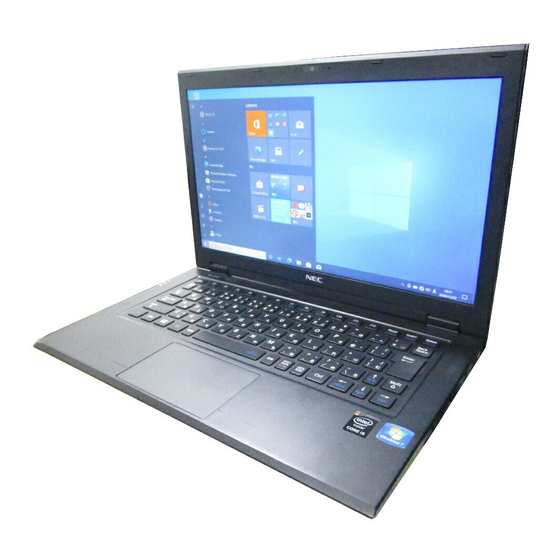
User's Guide
VG Model
®
7 Professional 64-bit with Service Pack 1 (SP1) or Windows
8
LAN Function....................................................................... 12
9
Wireless LAN Function........................................................ 12
10
System Configuration .......................................................... 14
11
Security Chip Function ........................................................ 15
12
Applications ......................................................................... 16
13
Recovery ............................................................................. 18
Appendix ............................................................................. 23
®
®
7 Professional 64-bit with
Advertisement
Table of Contents

Subscribe to Our Youtube Channel
Related Manuals for NEC VERSAPRO VG


Summary of Contents for NEC VERSAPRO VG
-
Page 1: Table Of Contents
User's Guide VG Model This User's Guide contains information primarily specific to this computer, assuming that the user is able to perform basic Windows operations and ® understands how to use help in its installed applications to resolve problems. In this user's guide, unless specified, "Windows 8.1" refers to Windows ®... -
Page 2: Checking Included Accessories
Instructions For Safe Use 安全にお使いいただくために Important points when connecting NEC软件的使用条件 【即EULA】(对顾客的特别提示) • Do not touch connector terminals when connecting any items. (请务必先仔细阅读如下内容后,决定是否打开本个人电脑的包装) Failure to do so may cause damage. Terms and Conditions for using software (For Customer) •... -
Page 3: Windows Setup
Turning on the power Windows Setup When you first power up your new computer, it is necessary to perform Windows setup. If the AC adapter is not properly connected, the power is not turned on by pressing the power switch when you first turn the power on. Check that the AC adapter is connected Important points during setup again. - Page 4 When the personal setting screen appears, select a desired color, enter the After checking the contents, check [I accept the license terms] and click [PC name], and click [Next] to continue. [Next] to continue. If you do not accept the license terms, setup cannot continue. Setup cannot progress to the next step unless you enter a valid PC name.
- Page 5 <Activation via Internet> If you encounter problems during setup Click [Go to PC settings]. When the computer is connected to the Internet, the Windows system is The setup screen is not displayed activated automatically. When [Press F2 to Enter BIOS Setup] is displayed on the screen when you turn the <Activation by phone call>...
-
Page 6: Knowing The Parts
Click [Finish]. Knowing the Parts • Do not select [Mark Partition as Active] for the newly created partition. Names and descriptions of your computer's major • It is not possible to shrink the [Recovery Partition]. The front and right sides •... - Page 7 Explanation of Components Number Name Explanation Number Name Explanation (15) USB port (supports USB This port can be used to connect to USB devices. 3.0, Power Off USB This USB port supports USB 3.0, USB 2.0, and LCD display This is the computer's display.
-
Page 8: Keyboard
Status LEDs Keyboard Power LED LED state Computer State Using the keys Blue Computer power on Flashing Sleep Hotkeys (Using <Fn>) Orange Low battery Low battery during sleep By pressing the function key <Fn> in combination with another key, you can easily Flashing change common computer settings. -
Page 9: The Nx Pad
Tapping a fingertip against the pad results in a click. Quickly tapping the pad twice The NX Pad results in a double-click. Tapping the pad to produce a click or double-click is called "tapping" or "double tapping". If you tap the pad with the pointer aligned on the target, and then touch the pad again and move your finger, this operation will result in a drag. -
Page 10: External Display
® Intel WiDi External Display ® ® The Intel WiDi (Intel Wireless Display) function uses the wireless LAN functionto display the screen of this computer on an external display or TV set that has the Switching Display Outputs ® Intel WiDi adapter. - Page 11 <For Windows 7> <For Windows 7> ® • The Intel WiDi adapter must support connection with the PC running on the WiDi ® Attach the Intel WiDi adapter to an external display or TV set. 5.1 system. For details, consult the adapter manufacturer. ®...
-
Page 12: Lan Function
LAN Function Wireless LAN Function This section covers important points and the correct procedure for setting up the LAN Turning the wireless LAN on/off (Local Area Network) function. The following methods can be used to turn the wireless LAN on and off. LAN settings <For Windows 8.1>... - Page 13 Click [Connect] after confirming that the [Connect automatically] checkbox For Windows 7 is selected. Turning the wireless LAN on and off with the wireless switch (<Fn> + <F2>) The automatic connection settings can be changed any time when desired. You can turn the wireless LAN function on and off by pressing the <Fn> + <F2> If a window comes up asking for a [Security key], enter the security key of keys on the keyboard.
-
Page 14: System Configuration
Function/Operation System Configuration <Enter> • Brings up a list of possible configuration values for the current item or displays the selected menu. It is also used to select a setting value and close the menu. • Displays the sub-menu for items that are highlighted with a symbol. -
Page 15: Security Chip Function
If a confirmation screen is displayed after the computer restarts, press Security Chip Function <Shift> + <F10>. The settings are saved and the computer restarts. The security chip is now initialized. Outline To use the security chip again, enable it by following the procedure of "Enable the security chip". -
Page 16: Applications
For Battery tool and diagnostic results, start the Battery tool, and click [Help] to read Applications the [Help] information. Performing Battery Refresh and Performance Diagnostics ® For battery refresh and performance diagnostics, perform the following steps. Microsoft Office Single Image v15 When performing battery refresh and performance diagnostics, the battery and the AC ®... - Page 17 • DoD-introduced mode (3 times erasure + Verify) If the [Battery tool Files in Use] screen is displayed, click [NEC Battery Deletes data from the SSD in a method compliant to the U.S. Department of Tool-Scheduler (Process Id:XXXX)], and then click [Continue].
-
Page 18: Recovery
From the [Boot Override] option, select the optical drive using <> or <> key, and press <Enter>. Recovery The [Boot Override] is contained in the [Exit] option. When [Press any key to boot from CD or DVD...] is displayed, press <Enter>. Recovery Basics If it is not displayed, go to Step 8. - Page 19 Do not interrupt recovery Do not interrupt the recovery process once it has started. The setup program is If you are using the VG22T/GG-L, be sure to initialize the security chip using the BIOS running normally even if the screen appears to stop, so please wait without setup utility before the computer recovery.
- Page 20 From the [Boot Override] option, select the optical drive using <> or <> key, remove my files" to delete personal files only, or "Fully clean the drive" to clean up the and press <Enter>. drives and disable them in order to easily complete the recovery operation and enhance security.
- Page 21 Connect the "recovery drive" you have created to the USB port of the computer. When the [User Account Control] screen appears, click [Yes]. Turn the power on and immediately press <F2> key several times. The BIOS setup utility will then be started. Click at lower left of the start screen.
- Page 22 When the [Windows Recovery] screen is displayed, select [Start to restore Windows Setup your computer], and press <Enter>. Perform Windows setup. Follow the steps on the screen for the procedure. Windows Setup Next, continue to "Windows Setup" (p.22). Set up the Windows system by referring to " Windows Setup"...
-
Page 23: Appendix
Switching the Windows system to another version Appendix Outline Disabling the "Fast Startup" function (Windows 8.1) The "Fast Startup" function allows quick computer startup from the power-off state. The ® If you are using the VG22T/GG-L Windows 7 Professional 64-bit with Service Pack 1 "Fast Startup"... -
Page 24: Specifications
Creating a recovery drive (Windows 8.1) Specifications We recommend that a "recovery drive" be created for times when problems such as Model name VC22T/GG-L,VG22T/GG-L corrupted files result in Windows not loading correctly. ® Intel Core i5-5200U processor Maximum memory (RAM) 4 GB onboard [fixed] Power Lithium polymer battery (DC 14.8 V, Typ. - Page 25 Model number list Model name Model number VC22T/GG-L PC-VC22TGGCLEBL, PC-VC22TGGCLECL, PC-VC22TGGDLEBL, PC-VC22TGGDLECL, PC-VC22TGGJZEBL, PC-VC22TGGJZECL, PC-VC22TGGMZEBL, PC-VC22TGGMZECL VG22T/GG-L PC-VG22TGGEBEEL, PC-VG22TGGEBEFL, PC-VG22TGGEBE1L, PC-VG22TGGEBE2L, PC-VG22TGGEBEJL, PC-VG22TGGEBELL, PC-VG22TGGFBEGL, PC-VG22TGGFBEHL, PC-VG22TGGFBE3L, PC-VG22TGGFBE4L, PC-VG22TGGFBENL, PC-VG22TGGFBEPL, PC-VG22TGGNBERL, PC-VG22TGGNBESL, PC-VG22TGGNBE5L, PC-VG22TGGNBE6L, PC-VG22TGGNBEVL, PC-VG22TGGNBEWL PC-VG22TGGNBETL, PC-VG22TGGNBEUL, PC-VG22TGGJTEEL, PC-VG22TGGJTEFL, PC-VG22TGGJTE1L, PC-VG22TGGJTE2L, PC-VG22TGGLTEGL, PC-VG22TGGLTEHL, PC-VG22TGGLTE3L, PC-VG22TGGLTE4L, PC-VG22TGGMTERL, PC-VG22TGGMTESL,...
- Page 26 MEMO...
- Page 27 MEMO...
- Page 28 MEMO...
- Page 29 MEMO...
- Page 30 MEMO...
- Page 31 MEMO...
- Page 32 In the event that the product is used for the above facilities and/or equipment or in control systems, etc. where personal injury and/or property damage is caused, NEC assumes no responsibility.
Need help?
Do you have a question about the VERSAPRO VG and is the answer not in the manual?
Questions and answers