Table of Contents
Advertisement
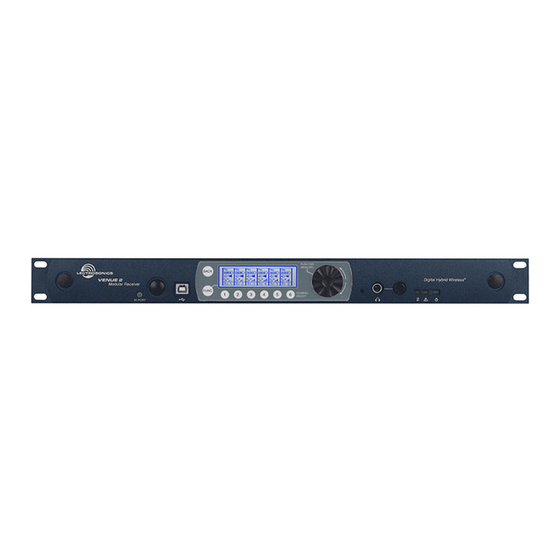
Venue 2 Modular Receiver
With Built-in Multicoupler
Hardware/Software Installation and Configuration
Fill in for your records:
Serial Number:
Purchase Date:
Essential Setup Steps for Operation
1) Install receiver modules, connect antennas and power supply
2) Install transmitter batteries and antennas
3) Identify and set operating frequencies on the receiver using
Smart Tune
and set frequencies on the transmitters
TM
4) Attach microphones and adjust transmitter input gain
5) Verify operation with a walk test through the area where the
system will be used
INSTALLATION GUIDE
Rio Rancho, NM, USA
www.lectrosonics.com
Advertisement
Table of Contents

Subscribe to Our Youtube Channel
Related Manuals for Lectrosonics Venue 2


Summary of Contents for Lectrosonics Venue 2
- Page 1 INSTALLATION GUIDE Venue 2 Modular Receiver With Built-in Multicoupler Hardware/Software Installation and Configuration Essential Setup Steps for Operation 1) Install receiver modules, connect antennas and power supply 2) Install transmitter batteries and antennas 3) Identify and set operating frequencies on the receiver using...
- Page 2 Venue 2 Wideband Receiver LECTROSONICS, INC.
-
Page 3: Introduction
Modular Receiver System ® Introduction Wireless Designer Software The Venue 2 Wideband receiver is a modular rack The software GUI provides an overall view mount design for use with a wide variety of transmitters of the system, including all mainframes from Lectrosonics and other manufacturers. -
Page 4: Table Of Contents
• Connect the equipment into an outlet on a circuit different from that which the receiv- er is connected • Consult the dealer or an experienced radio/TV technician for help Changes or modifications to this equipment not expressly approved by Lectrosonics, Inc. could void the user’s authority to operate it. LECTROSONICS, INC. -
Page 5: Safety, Fcc And Ic Notices
Digital Hybrid Wireless Modular Receiver System ® Important Safety Instructions 13) Unplug this apparatus during lightning storms or This symbol, wherever it appears, alerts when unused for long periods of time. you to the presence of uninsulated dan- gerous voltage inside the enclosure -- volt- 14) Refer all servicing to qualified service person- age that may be sufficient to constitute a nel. -
Page 6: Front Panel
Venue 2 Wideband Receiver Front Panel Rotary encoder Receiver select Infrared port Headphone Alert indicators buttons monitor The Venue receiver master unit (VRM) serves as a LCD Screen “host assembly” for up to six receiver modules. The standard module (VRS) and tracking module (VRT) can... -
Page 7: Rear Panel
Digital Hybrid Wireless Modular Receiver System ® Rear Panel Balanced audio Balanced audio Antenna inputs outputs outputs Network control Antenna outputs interface (loop thru) The rear panel provides six balanced XLR audio out- puts, antenna inputs, “loop thru” antenna outputs from Antenna Inputs an internal multicoupler, a power jack with a locking The two outermost BNC connectors are provided... -
Page 8: Hardware Installation
Venue 2 Wideband Receiver Hardware Installation Removing Receiver Modules Receiver Modules 1. Turn the power off. All modules must be within the frequency passband of the host assembly. Frequency bands are marked on 2. Gently pull outwards on the side panel and push the receiver modules. -
Page 9: Audio Outputs
Digital Hybrid Wireless Modular Receiver System ® Audio Outputs Balanced XLR audio outputs on the rear panel can be used to drive balanced or unbalanced inputs at line level on any type of mixer, recorder or other type of audio equipment. Note: When the modules are paired for diversity operation, the audio will appear at both XLR jacks associated with the module pair. -
Page 10: Lcd Interface
Venue 2 Wideband Receiver LCD Interface Navigating the Menus When the receiver is turned on, LCD will show the Three menus are provided for complete system setup: model number, firmware version and serial number • Top Menu for overall system settings during the boot sequence. -
Page 11: Using Setup Screens
Digital Hybrid Wireless Modular Receiver System ® Using Setup Screens The FREQ ADJUST setup screen in the RX Menu shown here is another type of a multiple module setup screen. The difference from the previous example is When a menu item is selected, a setup screen will that this type presents multiple settings within each open to enable adjustments and settings to be made. -
Page 12: Setup Details
Venue 2 Wideband Receiver Setup Details Audio Output Levels Setup The output level of the installed receiver modules can Direct Access to Receiver Setup be adjusted in a single setup screen in the RX Menu. Basic adjustments to each receiver can be made in a single screen available with the numbered Receiver Select button below the frame of each receiver. -
Page 13: Diversity Pairing
Digital Hybrid Wireless Modular Receiver System ® Optimizing the Signal to Noise Ratio Modulation (audio level) Given the information above, the optimum signal to noise ratio is achieved when the least amount of gain is applied to the signal, since gain (amplification) is the source of noise buildup. -
Page 14: Talkback Setup
A simple setup screen in the Venue 2 receiver makes it easy to des- ignate channels with this function enabled and which output will deliver the talkback audio. -
Page 15: Top Menu System Info
Digital Hybrid Wireless Modular Receiver System ® IR Transmitter Setup Top Menu SYSTEM INFO Firmware and hardware versions and the serial num- The IR (infrared) port simplifies transmitter setup by ber of the unit is listed in the SYSTEM INFO screen. sending the settings saved in the receiver to an IR en- abled transmitter. -
Page 16: Smart Tune Tm
Venue 2 Wideband Receiver Smart Tune After selecting the receiver to use for the scan, select START and press the encoder. The START item will change to STOP while the scanning is taking place. Clear frequencies can be discovered automatically us- ing the SmartTune utility. -
Page 17: Wireless Designer Software And Usb Driver
Help Menu. Refer to the help menu for details. WD 64-bit USB Driver... is for use with the DR digital receiver or Venue 2 receiver Launch the installer and follow the screen prompts. LecNet2 64-bit USB Driver... is for use with earlier... -
Page 18: Top Menu
9600 to SETTINGS is used to get settings from and 115200. send settings to a Lectrosonics transmitter on each channel. The LCD shows a listing of the frequency and nine configuration COMMAND VIEW opens a screen that settings on a single screen. -
Page 19: Rx Menu
PROG SWITCH defines the function of a programmable switch present on some TX BACKLIGHT sets how long the back- Lectrosonics transmitter models. The light on the transmitter LCD will stay turned switch function can be configured as audio on. The options may vary between different mute, power on/off, talkback or no function. - Page 20 Venue 2 Wideband Receiver SMART NR sets the desired noise reduc- tion mode for each channel: NORMAL, FULL or OFF. PHASE sets the polarity (phase) of each output to the desired value: NORMAL or INVERTED. RX LINK (DIVERSITY LINK) selects...
-
Page 21: Connecting To A Network
Digital Hybrid Wireless Modular Receiver System ® Connecting to a Network Firmware Update Instructions Using DHCP for IP Address Assignment Follow these steps to make a network connection for Firmware updates are made with a file downloaded the receiver: from the web site and a USB connection to the re- ceiver. -
Page 22: Antennas
To overcome loss is best to use remote antennas such as the SNA600 or in long coaxial cable runs, a Lectrosonics UFM Series ALP Series for optimum reception. Position the remote inline RF filter/amp should be positioned at the far end antennas at least three or four feet apart and not within of the coaxial cable, close to the antenna. -
Page 23: Multi-Channel System Checkout
Digital Hybrid Wireless Modular Receiver System ® Multi-channel System Checkout Interference can result from a wide variety of sources 4. Turn each transmitter off one at a time. including TV station signals, other wireless equipment With all transmitters and receivers turned on, turn in use nearby, or from intermodulation within a multi- each transmitter off one at a time, in turn, and channel wireless system itself. - Page 24 Venue 2 Wideband Receiver LECTROSONICS, INC.
-
Page 25: Accessories And Common Replacement Parts
Digital Hybrid Wireless Modular Receiver System ® Accessories and Common Replacement Parts Remote Antennas ALP500 ALP Series LPDA (log periodic dipole array) models ALP620 SNA600A folding dipole antenna ALP650 ALP Kit mounting hardware Coaxial Cable ARG2 coaxial cable - 2 ft. length ARG15 coaxial cable - 15 ft. -
Page 26: Service And Repair
There are no adjustments inside that will make a malfunctioning unit start working. LECTROSONICS’ Service Department is equipped and staffed to quickly repair your equipment. In warranty repairs are made at no charge in accordance with the terms of the warranty. Out-of-warranty repairs are charged at a mod- est flat rate plus parts and shipping. - Page 27 Digital Hybrid Wireless Modular Receiver System ® Rio Rancho, NM, USA...
-
Page 28: Limited One Year Warranty
This warranty does not apply to used or demonstrator equipment. Should any defect develop, Lectrosonics, Inc. will, at our option, repair or replace any defective parts without charge for either parts or labor. If Lectrosonics, Inc. cannot correct the defect in your equipment, it will be replaced at no charge with a similar new item.
Need help?
Do you have a question about the Venue 2 and is the answer not in the manual?
Questions and answers