Table of Contents
Advertisement
Quick Links
Download this manual
See also:
Installation Manual
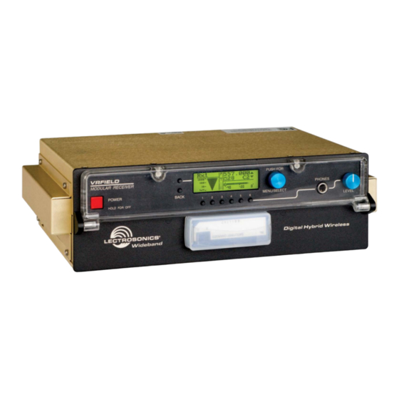
VR Field Wideband Receiver
Modular Receiver System with 230 MHz Bandwidth
Hardware/Software Installation and Configuration
Fill in for your records:
Serial Number:
Purchase Date:
Includes three versions:
• Wideband (blocks 21 through 29)
• Wideband Low (blocks 470 through 26)
• Wideband High (blocks 25 through 29)
INSTRUCTION MANUAL
Rio Rancho, NM, USA
www.lectrosonics.com
Advertisement
Table of Contents

Related Manuals for Lectrosonics Venue


Summary of Contents for Lectrosonics Venue
- Page 1 Hardware/Software Installation and Configuration Includes three versions: • Wideband (blocks 21 through 29) • Wideband Low (blocks 470 through 26) • Wideband High (blocks 25 through 29) Fill in for your records: Serial Number: Purchase Date: Rio Rancho, NM, USA www.lectrosonics.com...
- Page 2 VR Field Wideband Receiver LECTROSONICS, INC.
-
Page 3: Table Of Contents
Locking Out the Front Panel Controls ..............................18 Installing LecNet2 Software and USB Driver ...........................19 ™ Setting Up the Venue Receiver Using VRpanel ..........................22 Opening VRpanel with USB Port ................................22 Opening VRpanel with a COM Port ..............................22 VRpanel Main Window ..................................22 Main Window Top Menu Items ................................23... - Page 4 Connect the equipment into an outlet on a circuit different from that which the receiv- er is connected • Consult the dealer or an experienced radio/TV technician for help Changes or modifications to this equipment not expressly approved by Lectrosonics, Inc. could void the user’s authority to operate it. LECTROSONICS, INC.
-
Page 5: Introduction
RF environments. P1215 Battery Rain Shroud A Venue receiver is a “system” that consists of a master 21529-1 DB9-TRS stereo mini cable (BLACK) for unit and up to six receiver modules. Two different types... -
Page 6: Controls And Functions
Buttons Compartment Receiver Select Buttons The Venue receiver master unit (VRM) serves as a “host assembly” for up to six receiver modules. The The six Receiver Select Buttons are used to select indi- standard module (VRS) and tracking module (VRT) can... -
Page 7: Rear Panel
XLR Audio Output Jacks at the same level to deliver the RF signal to another Six balanced XLR audio output jacks connect the Venue Venue receiver. The second receiver can then feed a receiver to external equipment. By default, pin 2 is au- third receiver and so on, to create a “stack”... -
Page 8: Hardware Installation
Antenna A and B IN Retaining Clips Connectors jacks on the second unit. An additional unit can be connected to the second unit in the same manner. Note: All units connected in this manner must be on the same frequency block. LECTROSONICS, INC. - Page 9 Digital Hybrid Wireless™ Modular Receiver System Audio Output Wiring Diagrams Typical Lectrosonics Antenna Combinations ALP Series A500RA SNA600 NOTE: Frequencies of the receiver modules must be within the range of whip antennas and the SNA600 dipole. The ALP Series antennas are wideband designs that cover the entire range.
-
Page 10: Initial Startup
The display then switches to the overview of all six channels. When the Venue receiver is first powered up the LCD will show the firmware revision and the tuning range of the host assembly. The wideband version of the VRM covers the entire 230 MHz bandwidth of frequency blocks 21 through 29. -
Page 11: Navigating The Lcd Menus And Screens
Digital Hybrid Wireless™ Modular Receiver System Navigating the LCD Menus and Screens Front panel controls provide access to screens and In a setup screen such as the LockSet example shown menus for setup. The Function Button, Back Button, Re- here, up/down arrows prompt you to change the setting ceiver Select buttons and the MENU/SELECT control by rotating the MENU/SELECT control. -
Page 12: Resetting To Factory Defaults
• FULL applies more aggressive noise reduction with • Control panel lockout transparency superior to the noise reduction system used for many years in the earlier Lectrosonics Selecting Compatibility Modes wide deviation analog systems. Navigate to the Compat setup screen. -
Page 13: Selecting Diversity Modes
Digital Hybrid Wireless™ Modular Receiver System In this mode the signals from both antennas are com- bined into a single receiver module, with the phase of one of them inverted back and forth so that they always add to one another. The process reduces dropouts and provides a stronger signal than a single antenna. -
Page 14: Selecting The Tuning Mode
25 kHz steps for compatibility with older and non- gain control on one of the transmitters so that the Lectrosonics transmitters. Pilot tone frequency is set to audio loudness drops way down (nulls) as the two the next lower even 100kHz frequency. For example, channels cancel each other. -
Page 15: Finding Clear Frequencies With Smarttune
Digital Hybrid Wireless™ Modular Receiver System Finding Clear Frequencies with SmartTune In most cases the system will be ready to use after SmartTune has been run on all modules, however, it’s SmartTune simplifies setup by scanning the tuning a good idea to perform a system checkout to verify range of the receiver and automatically setting a re- the compatibility of the frequencies selected. -
Page 16: Adjusting Audio Output Levels
Adjusting Audio Output Levels the test tone. Note that this is output headroom. Over the entire 30+ dB range of the limiter in a Lectrosonics The audio output levels at the rear panel XLR jacks are transmitter, the output at the receiver goes up only 4.5 software controlled. -
Page 17: Selecting Audio Phase
Lectrosonics 200 Series and Digi- reliably identifiable voltage drops as they discharge. tal Hybrid models. The type of battery being used in the transmitter must be defined in the TxBatt setup screen. -
Page 18: Locking Out The Front Panel Controls
NOT LOCKED setting and press the control. When LOCKED is selected, no changes can be made to the configuration with the front panel controls. If an attempt is made to change a setting, the LCD will flash a reminder that the controls are locked. LECTROSONICS, INC. - Page 19 Digital Hybrid Wireless™ Modular Receiver System Installing USB Drivers This sequence and the screens are typical of installing The EULA (End User License Agreement) must be ac- the drivers on a computer running 64-bit Windows 7. cepted in order to continue the installation. Click on the radio button labeled I accept the EULA and then on Insert the disk into your local drive.
-
Page 20: Installing Lecnet2 ™ Software And Usb Driver
(you). Click Next to continue. The welcome screen will appear. Click on Next to pro- ceed to the installation. The next screen presents the EULA (end user license agreement) which must be approved to continue. Click LECTROSONICS, INC. - Page 21 Digital Hybrid Wireless™ Modular Receiver System When the confirmation screen appears, click on Next to continue with the installation. The installation takes place quickly, followed by the final screen that verifies that the software was installed cor- rectly. Click on Close to exit the installer. Rio Rancho, NM, USA...
-
Page 22: Setting Up The Venue Receiver Using Vrpanel
VRpanel is an intuitive software package that simplifies 2. Click on I would like to begin with a Blank con- the setup and operation of the Venue receiver. This sec- figuration. tion of this manual is limited to the basic setup and con- figuration. -
Page 23: Main Window Top Menu Items
Full descriptions and instructions for the menu items are presented in the online Help. With multiple Venue receivers, a pane opens for each receiver, with positions for up to six receiver modules in each. This lets you view and control all wireless sys- tems simultaneously on a single computer screen. - Page 24 Click on Delete VR in the popup menu to delete the running using the MC65 cable supplied with unit. Con- selected Venue receiver from the current VRpanel con- nect the PHONES jack output on the Venue Receiver figuration. front panel to the computer system’s audio input. Adjust the output level of the receiver with the LEVEL control on the front panel.
-
Page 25: Antenna Use And Placement
Antenna Use and Placement receiver’s antennas along with the direct signal. If the The Venue System is designed for rack mounting. direct and reflected signals are out of phase with each Although it can be operated with two whip antennas, it other and similar in strength, a cancellation or “drop-... -
Page 26: Pre-Coordinated Frequencies
The frequencies can be used FREQ SW SET US TV CH Grp a, the eight just with Digital Hybrid and analog Lectrosonics wireless 570.100 tv30 below them comprise 570.700 tv30 equipment. Compatibility with other brands is likely, but 571.600... -
Page 27: Compatibility Diagram
650.000 tv43/44 625.600 tv39 651.200 tv44 upper eight in the 626.100 tv40 651.700 tv44 with the Venue receiver, or researched in advance on 626.700 tv40 652.300 tv44 adjacent blocks. 632.300 tv41 657.900 tv45 this web site: www.fccinfo.com. 633.300 tv41 658.900... -
Page 28: Diagnostics
Scanning with the RF spectrum analyzer built into the a clear frequency is found, turn the transmitter on Venue system will identify external RF signals, but and move on to the next channel. it does not address the compatibility of the selected frequencies. -
Page 29: Accessories And Common Replacement Parts
Digital Hybrid Wireless™ Modular Receiver System Accessories and Common Replacement Parts Remote Antennas ALP Series LPDA (log periodic dipole array) models ALP500 ALP620 SNA600 folding dipole antenna ALP650/L ALP Kit mounting hardware Coaxial Cable ARG2 coaxial cable - 2 ft. length ARG15 coaxial cable - 15 ft. -
Page 30: Service And Repair
LECTROSONICS’ Service Department is equipped and staffed to quickly repair your equipment. In warranty repairs are made at no charge in accordance with the terms of the warranty. Out-of-warranty repairs are charged at a modest flat rate plus parts and shipping. - Page 31 Digital Hybrid Wireless™ Modular Receiver System Rio Rancho, NM, USA...
-
Page 32: Limited One Year Warranty
This warranty does not apply to used or demonstrator equipment. Should any defect develop, Lectrosonics, Inc. will, at our option, repair or replace any defective parts without charge for either parts or labor. If Lectrosonics, Inc. cannot correct the defect in your equipment, it will be replaced at no charge with a similar new item.
Need help?
Do you have a question about the Venue and is the answer not in the manual?
Questions and answers