
Related Manuals for Lectrosonics UCR210D


Summary of Contents for Lectrosonics UCR210D
- Page 1 UCR210 D DIVERSITY UHF RECEIVER OPERATING INSTRUCTIONS and trouble-shooting guide LECTROSONICS, INC. WWW.LECTROSONICS.COM Rio Rancho, NM...
-
Page 2: Table Of Contents
REAR PANEL CONTROLS AND FUNCTIONS ............ 7 ANTENNA USE AND PLACEMENT ..............8 INSTALLATION AND OPERATING INSTRUCTIONS .......... 9 UCR210D REPLACEMENT PARTS and ACCESSORIES ........9 FREQUENCY BLOCKS AND RANGES ............. 10 TROUBLESHOOTING ..................11 SPECIFICATIONS AND FEATURES ..............12 SERVICE AND REPAIR .................. -
Page 3: General Technical Description
The antenna phase SMART switching diversity technique was front ends, this was a daunting task. Lectrosonics has always used chosen in order to keep the receiver compact enough for camera front ends with more sections and much more selectivity than any mounted or shoulder bag applications. - Page 4 SURFACE ACOUSTIC WAVE FILTER that point necessary to pass the highest frequency audio signal The UCR210D is unique in that it uses a state of the art SAW filter present at the time. If the RF level is weak, then the filter becomes in the IF section.
- Page 5 +8dBm with no front panel control. POWER SUPPLY The UCR210D may be operated from an external DC source (see Specifications and Features section for allowed voltages.) The power supply has a built in Poly-Fuse to protect the unit. This fuse resets if the power supply is disconnected for about 15 seconds.
-
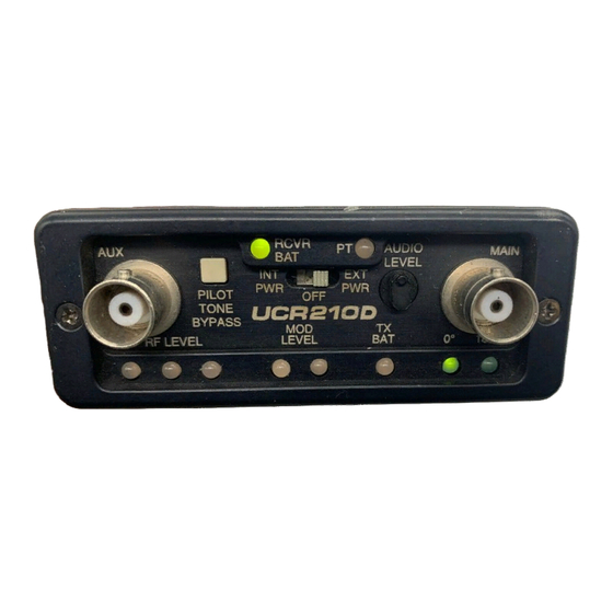
Page 6: Front Panel Controls And Functions
PT LED (Pilot Tone) GREEN as a power indicator. It doesn’t monitor the level of the The audio output muting (squelch) function of the UCR210D is external voltage. (Later versions of this receiver do monitor the controlled by a 32kHz tone modulation of the RF carrier. The external voltage as well as the internal battery voltage.) -
Page 7: Rear Panel Controls And Functions
REAR PANEL CONTROLS AND FUNCTIONS DC IN JACK BATTERY RELEASE The UCR210D can be powered from external DC applied directly To release the battery magazine, slide the battery release latch to this jack (see Specifications and Features section for allowed away from the audio output jack. -
Page 8: Antenna Use And Placement
UCR210D receiver, and the other one mounted re moving the antenna at least 3 or 4 feet from where it was. This may motely. -
Page 9: Installation And Operating Instructions
If the output is too low, you may hear steady noise (hiss) along with the audio. The UCR210D audio output is designed to drive any audio input device from microphone level to +8dBm line level. -
Page 10: Frequency Blocks And Ranges
The actual length of the antenna is not as critical as it might appear in the table Each UCR210D receiver is built to cover a pre-selected range of below. The usable bandwidth of the A8U antennas are +/- 50 MHz frequencies (a “block”) as shown below. -
Page 11: Troubleshooting
Mod level LED pair on the UCR210D front panel. switch is turned on • Audio output level too high for the device the UCR210D • It takes several seconds for the relay to actuate the is feeding. Lower the output level of the UCR210D. -
Page 12: Specifications And Features
SPECIFICATIONS AND FEATURES Operating Frequencies (MHz): Block 28 716.800 - 742.300 Block 21 537.600 - 563.100 Block 29 742.400 - 767.900 Block 22 563.200 - 588.700 Block 23 588.800 - 614.300 (outside USA) Block 30 768.000 - 793.500 (outside USA) Block 24 614.400 - 639.900 Block 31... -
Page 13: Service And Repair
LECTROSONICS’ service department is equipped and staffed to quickly repair your equipment. In warranty repairs are made at no charge in accordance with the terms of the warranty. Out of warranty repairs are charged at a modest flat rate plus parts and shipping. -
Page 14: Warranty
This warranty does not apply to used or demonstrator equipment. Should any defect develop, Lectrosonics, Inc. will, at our option, repair or replace any defective parts without charge for either parts or labor. If Lectrosonics, Inc. cannot correct the defect in your equipment, it will be replaced at no charge with a similar new item.
Need help?
Do you have a question about the UCR210D and is the answer not in the manual?
Questions and answers