Table of Contents

Related Manuals for Lectrosonics Venue Block 944


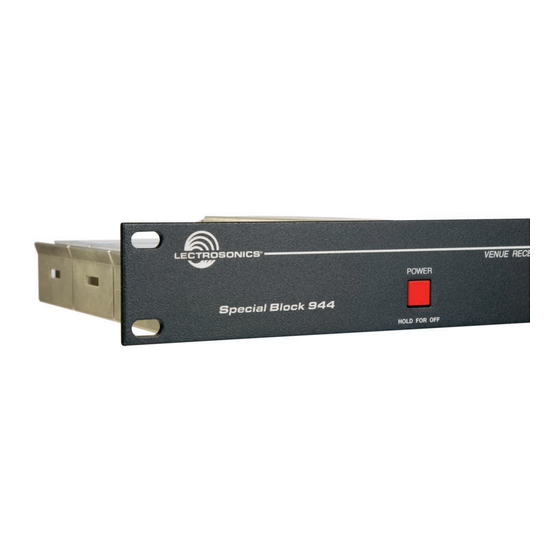
Summary of Contents for Lectrosonics Venue Block 944
- Page 1 INSTALLATION GUIDE Venue Block 944 Receiver Modular Receiver System for 944-952 MHz Band Hardware/Software Installation and Configuration Fill in for your records: Serial Number: Purchase Date: Rio Rancho, NM, USA www.lectrosonics.com...
- Page 2 Venue 944 Receiver LECTROSONICS, INC.
-
Page 3: Table Of Contents
The Venue is a modular rack mount receiver for use Introduction ................2 Venue System Controls and Functions ......... 4 with a wide variety of transmitters from Lectrosonics Front Panel ................4 and other manufacturers. The special block 944 model Rear Panel ................ -
Page 4: Venue System Controls And Functions
The LCD is a backlit, graphics-type Liquid Crystal Dis- play used to set up and monitor system operation. Receiver Select Buttons The six Receiver Select Buttons are used to select indi- vidual installed receiver modules, for monitoring via the LECTROSONICS, INC. -
Page 5: Rear Panel
Digital Hybrid Wireless™ Modular Receiver System Rear Panel Balanced Audio Balanced Audio Power Input Outputs 4-6 Outputs 1-3 Antenna Inputs Receiver RS-232 USB Port Receiver Modules 4-6 Port Modules 1-3 Multicoupler Outputs Antenna Input Jacks The rear panel provides six balanced XLR audio out- puts, antenna inputs, “loop thru”... -
Page 6: Hardware Installation
3. Pull outward on the module to release the connec- tor and then lift it upward out of the chassis. Holes in the underside of the chassis allow you to grip the module on the top and bottom. LECTROSONICS, INC. -
Page 7: Audio Outputs
Digital Hybrid Wireless™ Modular Receiver System Audio Outputs Connections for Computer Interface Balanced XLR audio outputs on the rear panel can be Connection to a computer can be made via USB or used to drive balanced or unbalanced inputs at line RS-232 ports. -
Page 8: Powering On And Off
Audio Level Meter In this example, channels 1 and 4 are being used; chan- nels 2, 3 and 4 have a receiver module installed, but the matching transmitters are not turned on. Channel 6 has no receiver module installed. LECTROSONICS, INC. -
Page 9: Resetting To Factory Defaults
Digital Hybrid Wireless™ Modular Receiver System Pressing the Receiver Select Button again will switch to the receiver module information screen to show the basic setup. Function Button If another option is available, it will appear in the left hand section of the LCD (“TONE” in this example). Press the Function Button to select and deselect this Press the BACK button twice to return to the overview option with repeated presses. -
Page 10: System Setup With The Lcd
• FULL applies more aggressive noise reduction with match the receivers transparency superior to the noise reduction system • Adjust audio output level used for many years in the earlier Lectrosonics • Select audio signal phase wide deviation analog systems. • Select transmitter battery monitoring mode •... - Page 11 Digital Hybrid Wireless™ Modular Receiver System Frequency Diversity Three diversity reception modes are available: • Switched Diversity uses one receiver module per audio channel. • Ratio Diversity (OptiBlend ) uses two receiver modules per audio channel. Frequency Diversity differs from the other two diversity •...
-
Page 12: Selecting The Tuning Mode
When the full spectrum has been scanned, the cur- sor will stop moving and blink briefly on the newly NORMAL MODE is the standard Lectrosonics mode selected frequency. with 79 frequencies in 100 kHz steps. A unique pilot tone is present for each frequency. -
Page 13: Finding Clear Channels With Tuning Group A
Digital Hybrid Wireless™ Modular Receiver System Finding Clear Channels with Tuning Group a 3. With the scanning stopped, select each receiver one at a time with the Receiver Select Buttons. The Group a contains 8 frequencies that can be used to- cursor for the selected receiver will blink. -
Page 14: Adjusting Audio Output Levels
Note that this is output headroom. Over software controlled. (The front panel LEVEL knob af- the entire 30+ dB range of the limiter in a Lectrosonics fects the PHONES output only.) transmitter, the output at the receiver goes up only 4.5 dB or less. -
Page 15: Locking Out The Front Panel Controls
Digital Hybrid Wireless™ Modular Receiver System Press the Function Button Selected Receiver to Reset (ZERO) the Timer Selected Receiver Elapsed Time Current Battery Types for Each is Highlighted Transmitter Receiver Module Battery Voltage Battery status is displayed on the receiver detail screen, (when available) the overview screen and the info screen. -
Page 16: Installing Lecnet2 ™ Software And Usb Driver
Windows Found New ® Hardware Wizard automatically opens. Use the follow- ing procedure to install the LecNet2 USB driver using ™ the Wizard. 1. Place the LecNet2 Installation Disk in the PC’s ™ CD-ROM drive. LECTROSONICS, INC. - Page 17 Digital Hybrid Wireless™ Modular Receiver System 5. When the driver installation is complete, the final page of the Wizard appears. Click “Finish” to close the Found New Hardware Wizard. 3. When the driver installation is complete, the final page of the Wizard appears. Click “Finish” to close USB Driver Installation (Windows XP) - the Found New Hardware Wizard.
- Page 18 Found New Hardware Wizard which will automatically load the LecNet2 USB driver ™ for the new device. 3. Check only CD-ROM drives then click “Next >” to search the LecNet2 CD for the USB driver. ™ LECTROSONICS, INC.
- Page 19 Digital Hybrid Wireless™ Modular Receiver System Rio Rancho, NM, USA...
-
Page 20: Setting Up The Venue Receiver Using Vrpanel
USB. Select the VR (Venue receiv- The Main Window shows all connected Venue receivers er) to be monitored or configured and then click OK with real time information for each receiver module. to add the receiver to the VRpanel configuration. Receiver information LECTROSONICS, INC. -
Page 21: Main Window Top Menu Items
Digital Hybrid Wireless™ Modular Receiver System Main Window Top Menu Items Popup Menu Items The Main Window is organized in a straightforward Right clicking anywhere in a receiver pane invokes a manner with three pull down menus. Brief descriptions context-sensitive and position-sensitive popup menu. of these menus are presented here as an introduction. - Page 22 Venue receiver from the current VRpanel con- figuration. The Walk Test Recorder produces a chart recording of RF signal strength versus time. Receiver modules in switched diversity mode leave a single trace; diversity pairs leave dual traces. LECTROSONICS, INC.
-
Page 23: Antenna Use And Placement
Long cable location. If dropouts are still a problem, try moving the runs can experience serious signal loss. Lectrosonics antennas to entirely different locations. offers in-line RF amplifiers suitable for compensating for this signal loss. -
Page 24: Diagnostics
BYPASS. In this example, the pilot tone for receiver in step 2. module 1 is set to BYPASS (BYP) and the others are set to NORMAL (NOR). LECTROSONICS, INC. -
Page 25: Accessories And Common Replacement Parts
Digital Hybrid Wireless™ Modular Receiver System Accessories and Common Replacement Parts Common Replacement Parts DCR15/1A2U power supply 24088 Pre-coordinated frequency groups (folded sheet) 21710-1 LecNet Cable for AMX/Crestron control 21529-1 LecNet Cable for RS-232 control 21713 USB Cable - 6 ft. long MC65 Cable - 1/4 inch male TRS to mini male TRS P1196 white receiver retaining clip P1204 receiver connector cover... -
Page 26: Service And Repair
LECTROSONICS’ Service Department is equipped and staffed to quickly repair your equipment. In warranty repairs are made at no charge in accordance with the terms of the warranty. Out-of-warranty repairs are charged at a modest flat rate plus parts and shipping. - Page 27 Digital Hybrid Wireless™ Modular Receiver System Rio Rancho, NM, USA...
- Page 28 This warranty does not apply to used or demonstrator equipment. Should any defect develop, Lectrosonics, Inc. will, at our option, repair or replace any defective parts without charge for either parts or labor. If Lectrosonics, Inc. cannot correct the defect in your equipment, it will be replaced at no charge with a similar new item.
Need help?
Do you have a question about the Venue Block 944 and is the answer not in the manual?
Questions and answers