Table of Contents
Advertisement
Quick Links
<Important>
Be sure to correctly follow the procedures in order as explained in this Installation Manual.
If you do not follow the procedure in order, the image trouble may occur.
I. Outline of installation procedures
AU-201
WT-510
When installing the machine and associated options as a system, follow the order shown on the upper.
Caution:
• For the detailed installation procedures for each
option, follow the instructions given in the corre-
sponding installation manual and perform the
procedures correctly. (Optional devices must be
installed after completing the main body instal-
lation.)
• When placing the machine on the floor, make
sure to use the paper feed cabinet or the desk
to secure the performance and the quality of
the product.
• Once the Power Switch is turned ON, do not
turn OFF it until the installation work has been
completed.
INSTALLATION MANUAL
PC-211
DK-511
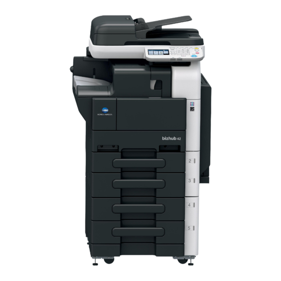
Machine
Electronic system options
MK-601
FS-529
/
Applied Machines:
• Lifting the machine in an awkward position or
transporting it in a poorly balanced position
could result in personal injury. When transport-
ing the machine, assign an adequate number of
persons to the job and ensure that each person
can take a good position of not being exces-
sively loaded. Machine mass:
• Approx. 63 kg (139 lb)
E-1
✱ Electronic system options
FK-509
A3EW-9591-00
/
A3EW11A001AA
Advertisement
Table of Contents

Related Manuals for Minolta Bizhub 36


Summary of Contents for Minolta Bizhub 36
- Page 1 INSTALLATION MANUAL Applied Machines: <Important> Be sure to correctly follow the procedures in order as explained in this Installation Manual. If you do not follow the procedure in order, the image trouble may occur. I. Outline of installation procedures ✱ Electronic system options PC-211 DK-511 FK-509...
-
Page 2: Accessory Parts
II. Installation space (unit: mm (inch)) IV. Accessory parts bizhub 42 + PC-211 + FS-529 Name Q’ty User’s guide holder 1173 (46-3/16) Quick guide 94 (3-11/16) 976 (38-7/16) (4-1/16) (Copy/Fax/Scan/Box operations) Installation manual 1 set User’s guide CD CD-ROM 1 set Paper size label Label (Legal restrictions on copying) * Label (IR Prohibited) -
Page 3: Removing The Machine
V. Removing the machine VI. Removing protective tape, packing and other shipping materials 1. Unpack the packaging box and remove cushion- ing materials and plastic bags from the box. 1. Remove the protective tapes and the protective 2. Hold onto the portions indicated in the illustration. materials. -
Page 4: Mounting The Accessory Parts
VII. Mounting the accessory parts 2. Remove the protective tape from trays 2 and 3. Install the supplied spacer onto the back of the main body. Note: This step may not be performed depending on the applicable marketing area. A3EW11A008AA A3EW11A013AA VIII. - Page 5 X. Affixing the Label (IR Prohibited) XII. Loading the developer Affix the label (IR Prohibited) to the position shown 1. Open the right door. below. 2. Remove the cover shown in the illustration. (One screw) 8 mm Note: • After removing the screw: (1) Raise the cover slightly.
- Page 6 4. Remove the imaging unit (IU) by placing your fin- 7. Remove the developing unit cover. gers under the hooks on its right and left sides, (Three screws) and pulling it toward you. A1UDIXC011DA A3EW11A015BA 8. Remove the toner supply port. 5.
- Page 7 10. Attach the mylar sheets. (Two places) 12. Remove the mylar sheets that were attached in step 10. (Two places) Note: Make sure that the collar is completely covered Note: with the mylar sheet. Discard the removed mylar sheets. 13. Reinstall the toner supply port. Note: Make sure of the correct mounting position and direction.
-
Page 8: Connecting The Power Cord
17. Screw the drum unit in position. (Two silver 20. Install the cover shown in the illustration. screws each on the right and left sides) (One screw) Note: Note: Use care not to touch or scratch the photo conduc- Make sure that the hole of the cover is aligned with tor. -
Page 9: Installing The Toner Bottle
XVI. Installing the toner bottle 2. Plug the power cord into the power outlet. Note: The toner bottle is not shipped with the machine. Purchase one that is separately available. 1. From a height of about 10 cm, tap the toner bottle against a table or other hard object four to five times. - Page 10 4. Open the front door and slide the toner hopper 8. Gently peel off the seal toward you from the bot- out of the machine. tle. Note: Perform this procedure slowly, as toner can burst out when the seal is peeled off. A1UDIXC015DA 5.
-
Page 11: Date/Time Setting
XVIII. Setting gradation adjust 7. Touch “Gradation Adjustment” “Print” “OK”. Test pattern will then be produced on the A4 or 1. Load A4 or Letter size papers in the tray. Letter size paper. 2. Display the Service Mode screen. 8. Touch “Scan”. (For details of how to display the Service Mode Using the steps below, follow the panel display to screen, see the service manual.) -
Page 12: Install Date
XX. Install date XXII. Adjusting registration of paper source options 1. Display the Service Mode screen. (For details of how to display the Service Mode 1. Load trays 4 and 5 with A4 or Letter size papers. screen, see the service manual.) 2. -
Page 13: List Output
8. Watching the graduations provided in the drawer, 8. Turn ON/OFF the Power Switch. move the edge guide in the rear. Note: • If the difference is greater than the specified If Service Mode was displayed, you must turn off value, move the edge guide toward the front. -
Page 14: Network Setting
XXV. Network setting Make the TCP/IP address setting for the network. Note: The IP address is assigned automatically by the DHCP server, when the machine's power is turned ON. (DHCP setting at the time of factory shipment: <To Set Manually> If the machine’s IP address is not set automatically, follow the steps below to set it manually.
Need help?
Do you have a question about the Bizhub 36 and is the answer not in the manual?
Questions and answers