Table of Contents
Advertisement
User Manual for Cellswitch 100
C
ELLSWITCH
CONTROL ANYTHING WITH YOUR CELLPHONE
cellphone
remotely monitor and control
Use your
to
Security: Electric Fence / Power-failure / Fire Sensors / Alarm Sensors
Access Control: Open your gate or Garage with your cellphone
Home Automation: Under-Floor Heating / Geyser / Lights / Plugs / Stove
Industrial: Cold Room Monitoring / Temperature Monitoring / Process Monitoring and Control
Farms: Pivot control / Irrigation / Water-level / Security
100
the following applications with the
CELLSWITCH 100
Page 1 of 23
Advertisement
Table of Contents

Summary of Contents for Accentronix CELLSWITCH 100
- Page 1 User Manual for Cellswitch 100 ELLSWITCH CONTROL ANYTHING WITH YOUR CELLPHONE cellphone remotely monitor and control CELLSWITCH 100 Use your the following applications with the Security: Electric Fence / Power-failure / Fire Sensors / Alarm Sensors Access Control: Open your gate or Garage with your cellphone ...
-
Page 2: How Does Is Work
How many different devices can I monitor and control? With the Cellswitch 100 you can monitor two different devices and control one at the same time. In other words you can monitor your alarm system, mains power and open and close your gate with a single device. -
Page 3: Caution
If in doubt about the operation of this device please consult the nearest AccentroniX distributor. This manual is subject to change without notice. -
Page 4: Table Of Contents
User Manual for Cellswitch 100 Table of Contents How does is work? Caution Key Features System Requirements Connection Diagram Installation Power supply Sim card Antenna Physical Dimensions Digital Input Relay Output SMS Configuration / Setup / Programming General Specification Diagnostics... -
Page 5: Key Features
User Manual for Cellswitch 100 KEY FEATURES 2 x Digital Inputs To monitor alarms, sensors, etc. 1 x Relay Output To switch lights on/off, open gate/garage, etc. Controllable via voice-call Simply call the device with your cellphone to control the output. -
Page 6: System Requirements
User Manual for Cellswitch 100 SYSTEM REQUIREMENTS Programming: The Cellswitch is programmed by sending it sms messages from your cellphone containing specific commands. Whenever a valid command is received by the device, a confirmation sms will be sent back to you stating that the device was successfully programmed. If the device receives a random sms containing invalid data, the sms will be discarded and no sms will be sent back. -
Page 7: Installation
User Manual for Cellswitch 100 INSTALLATION Power Supply: Wiring Techniques Wiring for the device has been designed to be safe and easy. If the user is concerned about the correct installation of these products or associated products, please contact a professional electrician who is trained to the local and national standards applicable to the installation site. -
Page 8: Sim Card
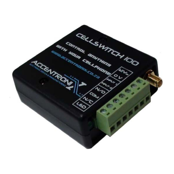
For more information on acquiring the above contract, please contact us. Antenna: Do not install the Cellswitch 100 inside a metal enclosure unless the antenna sits on the outside of the enclosure. Physical Dimensions: Length = 77mm ... -
Page 9: Digital Input
User Manual for Cellswitch 100 Digital Inputs: When the input is triggered either high or low it will send a SMS to the programmed reporting numbers. Terminal “IN” is internally pulled low. Leaving the connection open or connecting it to “0V”... -
Page 10: Relay Output
The output is used to switch circuits on and off and is controlled by sending a sms from your cellphone to the Cellswitch 100. The output can also be control by calling the Cellswitch from your cellphone. When the device receives your call it will automatically disconnect you, handling it as a missed call at no charge to you. -
Page 11: Sms Configuration / Setup / Programming
User Manual for Cellswitch 100 SMS Configuration / Setup / Programming IMPORTANT !!! PLEASE READ BEFORE ATTEMPTING TO PROGRAM THE DEVICE There are three different ways to program this device: 1.) Via our secure, easy to use, Gateway website https://cellswitch.accentronix.co.za/ 2.) By sending it SMS commands as described below. -
Page 12: General Setup
User Manual for Cellswitch 100 STEP 1 – Program the device’s own name, cellphone number and behaviour when it is called. GENERAL SETUP Device Name (Default: Cellswitch 100) 1234.F1"Cellswitch 100" The device's name displayed in the SMS reports. Device’s own cellphone number 1234.F2"0827727789"... - Page 13 User Manual for Cellswitch 100 STEP 2 – Program the desired security settings. SECURITY Add security numbers 1234.F4a”0827727789;0825091827;” When the unit is used for access or remote control. Only these cellphone numbers will be accepted by the unit when it is called.
- Page 14 User Manual for Cellswitch 100 STEP 3 – Program the cellphone numbers the device must SMS when an input is triggered. SMS REPORTING OPTIONS SMS Reporting number 1 1234.F6a”0827727789” Programs the first number to SMS and/or dial when an input is triggered.
- Page 15 User Manual for Cellswitch 100 SMS REPORTING OPTIONS --- CONTINUED Send Power-up SMS report 1234.F8on When the power to the device was interrupted it will send a notification SMS when power is re-applied. Do not send Power-up SMS report (Default) 1234.F8off...
- Page 16 User Manual for Cellswitch 100 STEP 4 – Program the SMS messaged that will be sent when the inputs are triggered. DIGITAL INPUT OPTIONS Input 1 high SMS 1234.F9a”Sensor 1 triggered” The SMS that will be sent when Input 1 is High (5 to 24 volt).
- Page 17 User Manual for Cellswitch 100 DIGITAL INPUT OPTIONS --- CONTINUED Call the reporting numbers 1234.F12on The device will first SMS, then call the reporting numbers when an input is triggered. Do not call the reporting numbers (Default) 1234.F12off The device will only SMS and not call the reporting numbers when an input is triggered.
- Page 18 User Manual for Cellswitch 100 STEP 5 – Program how the output relay must behave when the device is called or sent a SMS. OUTPUT RELAY OPTIONS 1234.On Switch the RELAY OUTPUT ON 1234.Off Switch the RELAY OUTPUT OFF Output PULSE mode (Default) 1234.F15a...
- Page 19 User Manual for Cellswitch 100 OUTPUT RELAY OPTIONS --- CONTINUED Output relay switching ON confirmation SMS 1234.F16a"Lights switched on" When the unit is called and the output relay is switched on, this confirmation SMS will be sent back. Output relay switching OFF confirmation SMS 1234.F16b"Lights switched off"...
- Page 20 User Manual for Cellswitch 100 STEP 7 – Test the device by checking GSM signal strength, inputs and outputs. SMS I/O CONTROL COMMANDS 1234.Status Request Input/Output and signal quality status. 1234.Signal Requests the GSM signal strength 1,0 = Bad Signal.
-
Page 21: General Specification
User Manual for Cellswitch 100 General Specifications: Operating Temperature -10ºC to +50ºC Storage Temperature -40ºC to +70ºC Operating Humidity 35 to 85% Relative Humidity, No Condensation Storage Humidity 35 to 90% Relative Humidity, No Condensation Vibration Resistance 10 to 57 Hz: 0.075mm Half Amplitude - Direct Mounting 57 to 150 Hz: 4.9 m/s²... -
Page 22: Diagnostics
User Manual for Cellswitch 100 Diagnostics Preliminary Checks Before Power up □ Check 230Vac Power Supply Wiring □ Check Ground Wiring □ Check Digital Input Wiring □ Check Relay Output Wiring □ Check Sim Card Power the device up Check that Power LED turns on for about 10 seconds, then start flashing.
Need help?
Do you have a question about the CELLSWITCH 100 and is the answer not in the manual?
Questions and answers