Advertisement
Quick Links
Download this manual
See also:
Operating Manual
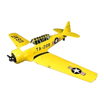
The following information relates to the construction / assembly of a HobbyKing AT-6
"Texan" – including what are considered (IMHO) to be reasonable and worthwhile
modifications.
The specifics of the model as provided by HobbyKing are as follows:
Specs:
Wingspan: 1300mm
Length: 956mm
Height: 380mm
Flying Weight: 1350g
Motor: 760KV brushless outrunner
ESC: 30A brushless
Servo: 9g x 4, 17g x 2
Battery: 2400mAh~2700mAh (required)
Propeller: 11x8
Includes:
User manual
Engine Sound Module System
All necessary hardware
Requires
6CH transmitter and receiver
3S 11.1V 2400~2700mAh lipoly battery
1
Advertisement

Related Manuals for HobbyKing AT-6 Texan


Summary of Contents for HobbyKing AT-6 Texan
- Page 1 The following information relates to the construction / assembly of a HobbyKing AT-6 “Texan” – including what are considered (IMHO) to be reasonable and worthwhile modifications. The specifics of the model as provided by HobbyKing are as follows: Specs: Wingspan: 1300mm...
- Page 2 Issues Encountered on Assembly Speed control failed on powering up – replaced (by way of account credit) by HobbyKing, One flap servo inoperative on arrival - replaced (by way of account credit) by HobbyKing, Missing sound module mount - replaced (by way of account credit) by HobbyKing.
- Page 3 Initial Flight The aircraft has a maiden flight on September 23 – actually two flights – which were both without incident or issue. All concerned onlookers were reasonably well impressed with the sound system output. The sound was in keeping with the speed and all agreed it was a good result. Tip Stall Incident On the third flight a tip stall was experienced with the aircraft being damaged on impact.
- Page 4 MODIFICATIONS Canopy The rear central window of the canopy was removed using a small Dremel grinding tip. This should assist in allowing additional heated air to be exhausted from the aircraft’s internal spaces. It also allows air introduced by the propeller to be exhausted – without this the canopy will overcome the magnetic catch and lift –...
- Page 5 The wing “saddle” structure was examined and the foam insert covering the underside of the saddle was carefully removed. This centre section is attached solely with contact cement (possibly deliberately as to allow repairs) and was removed. This exposes the cable channels below.
- Page 6 Wooden spar Buried tubular spar Original location of servo and lighting cable / PCB The space between the buried auxiliary spar and the wooded spar – in the original arrangement can be easily seen in this photograph. It is the space between the wooden spar and the rod that is used to accommodate the CF reinforcement.
- Page 7 Spar channel increased in fore and aft width to a depth equivalent to the wooden spar. This photograph indicates the channel created to house the carbon fibre reinforcement Carbon fibre spar shown in position prior to epoxying in place This photograph indicates the temporary fit up of the carbon fibre section in the channel area before epoxy gluing.
- Page 8 Carbon fibre reinforcement 400mm long and 10mm x 2mm prior to grinding and feathering This photograph is included to indicate the extent of the additional carbon fibre spar reinforcement outside the wing saddle. Whilst the wooden spars demonstrate dihedral the additional carbon fibre reinforcement is straight.
- Page 9 This means that all controls are readily accessible from within the cockpit area once the rearrangement is complete. The enlargement of the groove in the cover plate must be done to maintain the same level as original as the carbon fibre reinforcement finished upper edge is above the original wooden spar.
- Page 10 Rearrangement / Relocation of PCB Junction Plates and Associated Cables / Plugs To facilitate access the PCB junction plate attached on the outboard sides of the central wing saddle have been relocated to be inside and beneath the wing saddle cover plate. Obeche plate Relocated PCB plate epoxied in position...
- Page 11 Access From the Lower Sections of Fuselage to Cockpit Areas and Strengthening of Cockpit Sides In the absence of correct detail for installation of the sound module a reassessment of space was made within the fuselage by carefully introducing some openings in the “floor” area between the forward cockpit area and spaces immediately below.
- Page 12 Similar rework was carried out of the cowling on the side of the fuselage. This was a little more difficult but again careful probing and cutting with very small blades saw this cowl becoming a clear airflow path into the body of the fuselage. Opening in fuselage continued internally as to allow air flow from internal annular space immediately behind propeller There is now the possibility of air flow –...
- Page 13 Where these openings were made the transverse and longitudinal sides of the openings were strengthened with 10mm x 0.5 mm carbon fibre epoxied in place. Air Scoops – Lower and at Side Each of these were cleared of any foam within the openings and the fuselage internally opened up (carefully) as to allow air flow to internal spaces.
- Page 14 In an attempt to restore the yellow colour a second taping of translucent yellow wing tape from HobbyKing as also mentioned elsewhere was applied. The end result is not too bad – the yellow tape in two layers is as good as the equivalent...
- Page 15 As also mentioned elsewhere another yellow that is very close to the airplane colour as presented is Epsom colour printer yellow cartridge (140) in two coats – hardly notice any paint line. Dummy Radial Engine The foam between the cylinders of the faux engine was carefully removed as to allow increased airflow past the motor and the ESC.
- Page 16 The pilot’s feet provide further assistance in that when the canopy is secured the pilot’s feet securely hold the battery in location. No Velcro is used. Sound Module A ply wood plate was made – 1.5 mm ply –about 75mm x 35mm - onto which the sound module is secured.
- Page 17 Servos One flap servo was DOA so both were replaced with HobbyKing 928BB units. For information investigation as to the details of the original flap servos - with HK – indicated that the originals are Turnigy TSS - 9S slow speed servos.
- Page 18 Sound Module with cover removed Curiosity got the better of me so I removed the sound module cover to inspect. There is no volume control that I recognise as such. The cover was refitted. Cabling of the module is straightforward and there is now additional information on the HK website although reference is still made to volume control.
- Page 19 There are no spare parts for the “Texan” known to be available from HobbyKing although there are some for other models. I feel this is a missed opportunity for HobbyKing as without doubt customers would purchase them. Some of the OEM’s for the various other models DO make spare parts –...
- Page 20 It was noted that the shrink tube on the motor power cables was marked as ST 3511 760. Search of the HobbyKing site indicated that there are four HobbyKing Donkey ST series Donkey motors none of which corresponded with the marks on the motor removed.
Need help?
Do you have a question about the AT-6 Texan and is the answer not in the manual?
Questions and answers