Table of Contents
Advertisement
Quick Links
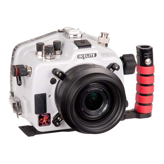
Underwater TTL Housing for Sony Alpha a7 II,
a7R II, a7S II
Product Number 6843.72
I n s t r u c t i o n M a n u a l
Thank you for your purchase of Ikelite equipment. Please read this instruction
manual completely before attempting to operate or dive with this product.
Please refer to the back page of this manual to register your Ikelite product.
Advertisement
Table of Contents
Troubleshooting

Subscribe to Our Youtube Channel
Related Manuals for Ikelite 6843.72


Summary of Contents for Ikelite 6843.72
- Page 1 I n s t r u c t i o n M a n u a l Thank you for your purchase of Ikelite equipment. Please read this instruction manual completely before attempting to operate or dive with this product. Please refer to the back page of this manual to register your Ikelite product.
-
Page 2: Table Of Contents
STROBE COMPATIBILITY and CONNECTION .....P. 16 Strobe Compatibility ..............P. 16 Housing Conversion Circuitry ..........P. 16 Attach Ikelite Sync Cord to the Housing and Strobe ....P. 17 ZOOM CLAMP and GEAR SLEEVE INSTALLATION ...P. 18 - 20 Manual Focusing ..............P. 20... -
Page 3: Important Information
IMPORTANT HOUSING INFORMATION This housing requires the addition of a compatible Lens Port for waterproof operation. Lens Port not included. Go to ikelite.com for Lens Port options. Your housing is setup to accept the Sony a7R II and a7S II camera models. - Page 4 IMPORTANT HOUSING INFORMATION - continued This housing features an integrated TTL circuit that is automatically powered by any DS-series strobe. Only Ikelite DS strobes are capable of powering the circuitry. Exposure compensation in TTL mode is supported using the camera’s built-in control. For manual flash operation, move the switch on the back of the housing Tray Mount to the left or “M”...
-
Page 5: Included In The Box
• Controls are not provided for AF/MF/AEL switch lever, Control wheel, or Diopter Adjustment Dial • Ikelite bulkhead connector with integrated TTL circuitry • Near neutral buoyancy in freshwater. Actual buoyancy varies depending on choice of lens and port •... -
Page 6: Preparation
PREPARATION This product has been water pressure tested at the factory and is depth rated to 200 ft (60 m). Thoroughly inspect and immerse the empty housing completely in water before installing a camera. If any fogging occurs or droplets of water enter the housing, do not install a camera. Clean the main housing o-ring and retest to make sure that the housing is watertight. -
Page 7: Parts Of The Housing - Front View
Parts of the Housing - Front View Exposure Compensation Dial ON/OFF Switch C2 Button Mode Dial / Lock Button 1/4-20 Light Accessory Mount Bulkhead Connector Quick Release Front Push Dial Button Zoom Knob IKELITE Accessory Port Lens Release Button... -
Page 8: Parts Of The Housing - Back View
Parts of the Housing - Back View Accessory Bulkhead Connector Port START/ MENU STOP DISP DISP Display Button 1. MENU BUTTON 2. Super-eye Viewfinder Self-Timer/Down Cursor 3. C3 (Custom 3) Button 10. SET Button ISO / Right Cursor 4. Rear Dial AF/MF / AEL Button Down Cursor Movie START/STOP Button... -
Page 9: Housing And Camera Setup Steps
HOUSING and CAMERA SETUP STEPS Step 1 - Initial Camera Settings Insert a fully charged battery. Set Mode Dial to “A” Aperture Priority. Manually adjust aperture setting to achieve the best exposure for your shooting conditions. The shutter speed will be locked at 1/30th-1/60th second. If a faster shutter speed is desired or you are NOT using an external strobe, set Mode Dial to “M”... - Page 10 Step 1 - Initial Camera Settings - continued SETUP MENU settings: Set Pwr Save Start Time to “5 min.” A ll other camera functions not mentioned should be set to the user’s preference.
-
Page 11: Step 2 - Opening The Housing
Step 2 - Opening the Housing Lid Snaps have a Lid Snap Lock. 1. Push Lid Snap Locks forward and lift as shown. Open opposing Lid Snaps simultaneously. Keep pressure on the Lid Snaps so they do not fly open quickly. - Page 12 Step 3 - Install Camera in Housing - continued Diagram A Pull to Remove Mounting Tray Mounting Plate 4. Using a coin or flathead screwdriver (preferred), secure the camera Mounting Tray to the camera tripod mount, Diagram B. Tighten camera firmly to Diagram B avoid movement on tray.
-
Page 13: Step 4 - Attach Hotshoe
Step 4 - Attach Hotshoe When connecting an external strobe to the housing bulkhead, slide the hotshoe into the top camera mount until it stops. Hotshoe must be all the way forward in the camera mount to assure a good electrical connection with a strobe, Diagram C, below. -
Page 14: Step 5 - Closing The Housing
Step 5 - Closing the Housing Lid Hook 1. Place housing face down in your lap. Check to see that there is an o-ring on the housing back, and that it is clean and in its proper location. 2. Guide the back onto the Even gap on housing front. -
Page 15: Step 7 - Housing Usage
Step 7 - Housing Usage Turn the camera on and operate each of the housing controls to get a feel for using the camera in the housing. Step 8 - Entering the Water As soon as you enter the water, take a moment and check to see that the housing is properly sealed. -
Page 16: Strobe Compatibility And Connection
This housing has Ikelite designed and patented Conversion Circuitry built right in. The Conversion Circuitry provides real TTL flash exposure when used with Ikelite DS series strobes. The circuitry is automatically activated once a DS series strobe is attached to the housing and turned on. Once attached, turn the strobe on first before turning on the camera. -
Page 17: Attach Ikelite Sync Cord To The Housing And Strobe
The Ikelite Housing and Strobe Bulkheads are designed to accept sync cords with Ikelite 5 pin connector fittings. 1. Lightly lubricate the Sync Cord O-rings. Use ONLY Ikelite lubricant (supplied with housing). Other lubricants may cause the o-rings to swell and seal improperly. -
Page 18: Zoom Clamp And Gear Sleeve Installation
Use the suggested Zoom Clamp and Gear Sleeve for your lens. Go to ikelite.com for a complete list of compatible lenses. The Zoom Clamp has springs so it can be expanded to fit over the Zoom Ring of the lens. - Page 19 Zoom Clamp and Gear Sleeve Installation - continued Diagram F Diagram G Zoom set 5509.27 Zoom set 5509.28 Lenses up to 2.8 in. diameter Lenses 2.8 - 3.0 in. diameter 9059.8 9059.9 Zoom Zoom Clamp Clamp Narrow grooved Wide grooved extension tabs extension tabs Long post...
-
Page 20: Manual Focusing
Housing Drive Gear Manual Focusing Ikelite DSLR housings are designed for auto-focus DSLR cameras and lenses. Manual focusing is not recommended. In some cases, if you desire to manually focus a lens, the Zoom Clamp can be moved onto the lens’s Manual Focus Ring. -
Page 21: Lens Ports
LENS PORTS A lens port must be secured to the housing before entering the water. Ikelite DSLR housings DO NOT come with a lens port. You must select the correct port for each lens you will be using underwater. To assure water-tightness, submerge the housing with port attached into a bathtub or shallow water without the camera installed. - Page 22 Installing the Port - continued Visually inspect each port lock and confirm that the Port Lock Release Button is seated FLUSH against the Port Lock Body. DO NOT rely only on an audible “click” to indicate that the lock is engaged. Check around the perimeter of the port seal to see that the o-ring is properly sealed and NOT extruded.
-
Page 23: Recommended Accessories And Attachments
4077.02 Right-Hand Quick Release Handle with Extension The optional right-handed release handle with tray mount comes with the necessary hardware to mount to your Ikelite housing tray. The Extension attaches to an existing Base with two included screws for stability and rotation-free use. - Page 24 2602.2 Flex Mount Kit for GoPro Gamma II Waterproof Flashlight 1887.1 DSLR Ball Mount Kit for Gamma A full range of accessories are available to support your housing. Please visit ikelite.com to see the most current information about recommended accessories for your housing.
-
Page 25: Spare Parts
O-ring Storage When storing the housing, remove the main housing o-ring. Lightly lubricate the o-ring until it appears shiny and place in a small resealable plastic bag. Use ONLY Ikelite lubricant. Place the bag inside the housing and store until needed. -
Page 26: Housing Maintenance
Housing Maintenance Your Ikelite Digital Housing should be given the same care and attention as your other photographic equipment. In addition to normal maintenance, we recommend that the housing be returned to Ikelite periodically to be checked and pressure tested. -
Page 27: Control Maintenance
Place the plastic bag with o-ring inside the housing for safe keeping. If removing a housing push button, Do Not re-use the E-clip. Contact Ikelite for replacement E-clips (part 0319.12). - Page 28 Lube Here Contact Ikelite for replacement E-clips (part #0319.12). Ikelite controls are designed to provide years of reliable service with minimal maintenance. In the unlikely event one of the control shafts sticks or becomes difficult to operate, you can remove the control from the housing and lubricate it, or return the housing to Ikelite for maintenance.
- Page 29 In the unlikely event one of these controls sticks or becomes difficult to operate, you can remove the control from the housing and lubricate it, or return the housing to Ikelite for service. To remove the control, Diagram K, page 30, loosen the set screw in the knob (allen wrench required);...
- Page 30 Control Maintenance - continued Loosen Set Screw Lubricate end of shaft (Hex Head Wrench Required) before reinserting into Diagram I gland Knob Control Shaft O-rings Control Gland Tighten set screw down against this flat area when replacing the knob Housing Lubricate Shaft Diagram J Housing...
-
Page 31: Photo Tips
PHOTO TIPS The number one rule in underwater photography is to eliminate as much water between the camera and subject as possible. Get as close as you can to the subject, then use the zoom. If you are using flash for still photos, subjects beyond 6 ft (1.8 m) will not have much color regardless of strobe power. -
Page 32: Troubleshooting
If still sticky, see the Control Maintenance section, pages 27-30. - Return housing to Ikelite for routine service Image is over/ - Check that the external strobe is firing when taking a underexposed, or a picture. - Page 33 Place one or two new packs in your housing before each day of diving. - Clean the main housing o-ring and sealing surface of the housing. - If moisture or water droplets are present around the controls or sealing areas, return the housing to Ikelite for evaluation.
-
Page 34: Customer Support
- Reassemble the housing without a camera installed and pressure test or take diving. - Return housing to Ikelite for routine service. Pictures are too - Move in closer to your subject when taking a blue or too green picture. -
Page 35: Limited Warranty
This Ikelite product is warranted against any manufacturing defects for a period of one (1) year from the original date of purchase. Defective products should be returned to Ikelite postage paid. Ikelite will, at its sole discretion, repair or replace such products, and will return to customer postage paid. -
Page 36: Product Registration
PRODUCT REGISTRATION Please go to ikelite.com to register your Ikelite housing within 15 days of purchase. Ikelite Underwater Systems 50 West 33rd Street Indianapolis, IN 46208 USA ikelite.com © 2016 Ikelite Underwater Systems 6843.72_sony-a7II_a7rII_a7sII_1-0116...
Need help?
Do you have a question about the 6843.72 and is the answer not in the manual?
Questions and answers