Table of Contents
Advertisement
Quick Links
SLR-DC Housing
i n s t r u c t i o n m a n u a l
#6801.70 for the Nikon D7000
Size and Weight
Width ................10 in. (250mm) including controls
..........................13.7 in. (348mm) with Tray and Handles
Height ..............7.0 in. (178mm) including controls
..........................7.3 in. (185mm) with Tray and Handles
Depth ................6.5 in. (165mm) including controls
Weight ..............5.5 lb (2495g) housing only
..........................7.8 lb (3538g) housing with tray & handles
Buoyancy ..........Neutral to slightly negative in fresh water (dependent on
..........................choice of lens and lens port)
IKELITE
Port Lock
Advertisement
Table of Contents

Related Manuals for Ikelite 6801.70


Summary of Contents for Ikelite 6801.70
- Page 1 SLR-DC Housing i n s t r u c t i o n m a n u a l #6801.70 for the Nikon D7000 IKELITE Port Lock Size and Weight Width ....10 in. (250mm) including controls ......13.7 in. (348mm) with Tray and Handles Height ....7.0 in.
-
Page 2: Table Of Contents
Installing the Port / Lens Ports ........P. 15 Housing Conversion Circuitry..........P. 17 Flash Dial / DS50, DS125 Substrobe Compatibility ..P. 18 Using Non-Ikelite or Ikelite Non-DS Substrobes ....P. 18 Usage ................P. 19 Pre-Dive Your System ............P. 19 Lubricants ................P. 19 Troubleshooting ............P. -
Page 3: Product Registration
Thank you for your purchase of Ikelite equipment. Please read this instruction manual completely before attempting to operate or dive with this product. Product Registration Please take a moment to fill out the online Ikelite Product Registration form at http://www.ikelite.com/forms/regForm.htm. Package Contents - SLR-DC Housing - Aluminum Tray &... -
Page 4: Parts Of The Housing / Size And Weight
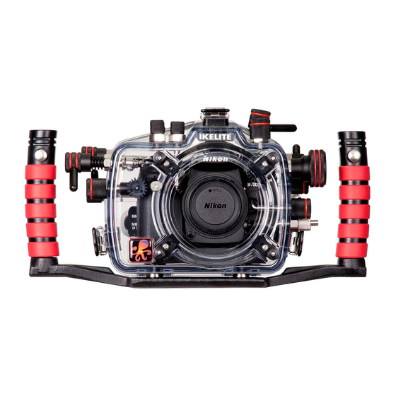
Parts of the Housing - Front View Quick Release Strobe Arm Mount Power Switch IKELITE Port Lock Gear Sleeve Handle Drive Gear Shutter Port Release Opening Snap Aluminum Tray Side View Metering, Power Switch Main Housing Optional Gear O-ring Port... - Page 5 Back View 18 19 28 29 30 1. Quick Release Button 18. Playback Button 2. Zoom Control 19. Delete Button 3. Flash Mode, 20. Menu Button 4. Mode Dial 21. White Balance 5. Super-eye Viewfinder 22. External Strobe Connector & Cap 6.
-
Page 6: Initial Camera Setup
Initial Camera Setup Insert a fully charged battery. Insert SD memory card (2GB or greater capacity recommended). Set the mode dial to “M” manual. Set Time Zone and Date. Set shutter speed to 1/60th second or 1/125th second for fast moving subjects. -
Page 7: Attaching Camera To Housing Tray
Attaching Camera to Housing Tray Remove the back from the housing. The mounting tray for the camera is secured to the housing back. Position the camera and lens on the camera tray, and then secure it with the mounting bolt which threads into the camera’s tripod socket. -
Page 8: Attaching The Flash Connection For External Strobes
Attaching the Flash Connection for External Strobes When using an external strobe, connect the housing hotshoe connector. Slide the connector into the hotshoe mount on the camera from the back of the camera as shown. Slide the connector forward until it stops. Due to limited clearance between the External Strobe Connector and... -
Page 9: Closing The Housing
Closing the Housing housing back 1. Place housing face down in your lap. 2. Check to see that there is an o-ring on the housing back that is clean and in its proper location. 3. Guide the back onto the housing. The o-ring should touch the housing all the way around. -
Page 10: Installing Zoom Clamp And Gear Sleeve
Preparing to Install Zoom Clamp & Gear Sleeve Determine the type lens opening of lens being used zoom on the camera. ring Type 1 Lenses have a lens opening that is NOT larger in diameter than the bayonet mount zoom ring. (Fig. 1). Type 1 lens Type 2 lens (Figure 1) - Page 11 Installing the Zoom Clamp & Gear Sleeve On the Type 1 Lenses The Zoom Clamp has springs so it can be expanded to fit over the Zoom Ring of the lens - figure C, page 11. Install the Zoom Clamp with the extension tabs toward the rear element of the lens.
- Page 12 Type 1 Lenses (cont.) Gear Sleeve Ribs Align Ribs with Zoom Clamp grooved tabs Figure D apply rubber strips to inside of clamp Figure E Figure F...
- Page 13 Installing the Zoom Clamp & Gear Sleeve On Type 2 Lenses Due to the larger diameter lens opening on Type 2 lenses, the Zoom Clamp and Gear Sleeve need to be installed from the rear (bayonet end) of the lens. Use the housing Lens Release Control and remove the camera lens from the camera body, after the camera and lens have been installed in the housing.
- Page 14 Control Knob to see that the Gear Sleeve is properly rotating the Lens Zoom ring. Manual Focusing Note: Ikelite DSLR housings are designed for auto-focus DSLR cameras and lenses. Manual focusing is not recommended. In some cases, if you desire to manually focus a lens, the zoom clamp must be moved onto the lens Manual Focus Ring and you must use the housing zoom control knob to manually focus.
-
Page 15: Installing The Port / Lens Ports
Installing the Port Port Lock There are four port locks on the Release Button front of the housing, see figure G, page 14. Each port lock has a Release Button. Lift the Locked Position release button and slide each Lift Release Port Lock away from the port Button to Unlock... - Page 16 Lens Ports A lens port must be secured to the housing before entering the water. Ikelite DSLR housings DO NOT come with a lens port. You must select the correct port for each lens you will be using underwater. For complete lens port information and compatibility with your Ikelite system, go to http://www.ikelite.com/web_pages/slrport.html.
-
Page 17: Housing Conversion Circuitry
The Conversion Circuitry also offers Manual exposure control with 3 1/2 f-stops of under-exposure control in 1/2 stop increments. The Conversion Circuitry is powered by the Ikelite DS Substrobe when connected to the housing with the #4103.51 single or #4103.52 dual sync cord. -
Page 18: Flash Dial / Ds50, Ds125 Substrobe Compatibility
Older DS50 Substrobes with Serial Number between 63,850 and 69,999 require upgrade of electronics to operate. Cost of update depends on strobe circuitry. Strobe must be returned to Ikelite for evaluation to provide an estimate of upgrade cost. Older DS125 Substrobes with Serial Number below 2,500 can NOT be updated to operate correctly with the latest TTL conversion circuitry. -
Page 19: Usage
Lubricants Ikelite provides silicone lubricant with the housing. We recommend that you use only Ikelite lubricant. Other brands may cause the o-ring to swell and not seal properly. Use only enough Ikelite lubricant to lightly cover control shafts and o-rings. -
Page 20: Troubleshooting
If still sticky, see the Control Maintenance section - pages 23 & 24. - Return housing to Ikelite for routine maintenance. Image is over- or - Check that the strobe(s) are firing when taking under-exposed a picture. - Page 21 - If water droplets or moisture is present around the controls or sealing areas, return the housing to Ikelite for evaluation. - Clean the main housing o-ring, port o-ring, and sealing surfaces of the housing.
-
Page 22: Replacement Parts
1/4-20 threaded mounting points for attachment of a tripod or other accessories. A full range of accessories is available to support your housing. Please visit http://www.ikelite.com/web_two/nik_d7000.html to see the most current information about recommended accessories. Please Read If Using an EV-Controller... -
Page 23: Maintenance
To lubricate the control, gently pull on the knob until the stainless steel shaft is exposed. Lightly lubricate the shaft, then move the shaft in and out several times. This will lubricate the x-ring in the Ikelite control gland. This should be done before using the housing after a prolonged storage period, or once a week when the housing is in constant use. - Page 24 Diagram A Housing Gland Control Shaft Tighten set screw down against this flat area Lubricate end of shaft Loosen set screw when replacing the knob. before reinserting into (allen wrench required) gland Diagram B Lubricate Shaft Housing Pull out to expose shaft...
- Page 25 Housing Maintenance Your Ikelite Housing should be given the same care and attention as your other photographic equipment. In addition to normal maintenance, we recommend your housing be returned to Ikelite (every 2-3 years or 50 dives), to be checked and pressure tested.
-
Page 26: Photo Tips
Photo Tips The number one rule in underwater photography is to eliminate as much water between the camera and subject as possible. Get as close as you can to the subject, then use the zoom. If you are using flash for still photos, subjects beyond 6 feet (1.8m) will not have much color regardless of strobe power. -
Page 27: Storing The Housing
This Ikelite product is warranted against any manufacturing defects for a period of one year from the original date of purchase. Defective products should be returned prepaid to Ikelite. Ikelite will, at its discretion, repair or replace such products, and will return to customer prepaid. All other claims of any nature are not covered. -
Page 28: Returning Products For Service
Evidence of purchase date must be provided to obtain warranty service. No prior authorization is required. You may return directly to Ikelite or through your dealer. Please include a brief description of the problem, any relevant e-mail correspondence, and/or instructions on requested service.
Need help?
Do you have a question about the 6801.70 and is the answer not in the manual?
Questions and answers