
Subscribe to Our Youtube Channel
Related Manuals for Lumens VC-G30


Summary of Contents for Lumens VC-G30
- Page 1 VC-G30 Camera Installation Guide - English [Important] To download the latest version of Quick Start Guide, multilingual user manual, software, or driver, etc., please visit Lumens http://www.Mylumens.com...
-
Page 2: Table Of Contents
Setting menu ..................22 Chapter 6 Descriptions of Major Functions ..........30 I would like to switch to VC-G30 ............30 I would like to save the current lens position data ......30 ... - Page 3 I would like to adjust the focal length ..........31 I would like to adjust the focus speed ..........31 I would like to set the image mode ........... 32 6.10 I would like to freeze images ............32 ...
-
Page 4: Copyright Information
Inc. Copying, reproducing or transmitting this file is not allowed if a license is not provided by Lumens Digital Optics Inc. unless copying this file is for the purpose of backup after purchasing this product. In order to keep improving the product, Lumens Digital Optics Inc. hereby reserves the right to make changes to product specifications without prior notice. -
Page 5: Chapter 1 Safety Instructions
Chapter 1 Safety Instructions Always follow these safety instructions when setting up and using the Camera: 1. Use attachments only as recommended. 2. Use the type of power source indicated on the Camera. If you are not sure of the type of power available, consult your distributor or local electricity company for advice. -
Page 6: Precautions
Precautions Warning: To reduce the risk of fire or electric shock, do not expose this appliance to rain or moisture. If Camera will not be used for an extended time, unplug it from the power socket. Note Risk of Electric Shock DO NOT OPEN Caution: To reduce the risk of electric shock, do not remove cover (or back). -
Page 7: Kcc Warning
KCC Warning A 급 기기 이 기기는 업무용(A 급) 전자파적합기기로서 판매자 또는 (업무용 방송통신기자재) 사용자는 이 점을 주의하시기 바라며, 가정 외의 지역에서 사용하는 것을 목적으로 합니다. English - 6... -
Page 8: Chapter 2 Package Contents
Chapter 2 Package Contents Instruction for VC-G30 Remote Control installation Power Cord Power Adapter RS-422 Connector Appearance may vary depending on country/region Metal Plate A Metal Plate B M3 Screws English - 7... -
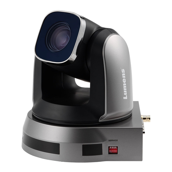
Page 9: Chapter 3 Product Overview
Chapter 3 Product Overview 3.1 Overview Front View Back View 1. Camera lens 2. Power LED indicator 3. Standby LED indicator 4. DVI output 5. Component output 6. Power input 7. IR SELECT 8. OUTPUT Switch 9. Camera Address Selectors 10. -
Page 10: Chapter 4 Instruction For Installation
Please determine an installation place according to the following requirements: 4.1.3.1 Confirm the position for the object to be captured. 4.1.3.2 Confirm whether the VC-G30 is set at a proper distance from other light sources. 4.2 Instruction for installation 4.2.1 I would like to install VC-G30 on the desk... - Page 11 4.2.2 I would like to install VC-G30 on the ceiling 4.2.2.1 Prepare for the parts and equipment required during the installation 1. Accessories of VC-G30 in the box (metal plates A, B and M3 screw x 7) 2. Screw for locking on ceiling mounted hanger x 4 3.
- Page 12 4.2.2.3 Max. rotation dimension of camera English - 11...
- Page 13 4.2.2.4 Size Diagram 1. Metal plate B - ceiling side Metal plate B locking screw Metal plate B locking bolt M3 threaded hole M3 threaded M3 threaded hole hole Metal plate B - ceiling side English - 12...
- Page 14 2. Metal plate A - machine side Metal plate A locking screw Metal plate A - machine side English - 13...
- Page 15 3. Bottom of machine English - 14...
- Page 16 4.2.2.5 Precautions for installation 1. Before installation, please confirm the orientation of the machine relative to the object to be captured 2. It is recommended that the machine should be set at a distance of more than 1 meter away from the object to be captured. Please adjust for a best distance according to the magnification of the lens 1 meter↑...
- Page 17 3. Lock the metal plate B on ceiling mounted hanger. ※Caution: (1) Please use the hanger that has obtained UL security approval (2) Please reserve the hole for the connecting wires of the camera 4. Combine the metal plate A and the metal plate B (1) Push the metal plate A up to the ceiling and then to the right to latch the metal plate B (2) Fix with 3 M3 screws...
- Page 18 4.2.2.7 How to remove 1. Remove the connecting wires from the camera 2. Uninstall the camera together with the ceiling, loosen the three screws that fix the metal plates A and B and push to the left to remove the machine 3.
-
Page 19: Connecting The Device
4.3 Connecting the device 4.3.1 Image output Connecting to a HDTV/computer monitor (DVI) 4.3.1.1 DVI cable Monitor HDTV Connecting to a TV (C-Video) 4.3.1.2 C-Video Cable English - 18... - Page 20 Connecting to a HDTV (3G-SDI) 4.3.1.3 SDI Cable HDTV Connection to the device for image output 4.3.1.4 Component adaptor HDTV English - 19...
- Page 21 4.3.2 Controlling VCs with the computer Connecting to one computer for connection between VCs 4.3.2.1 (RS-232 in/out) <Remark> With RS-232 in/out, at most 7 VCs can be connected. Connecting to one computer for connection between VCs 4.3.2.2 (RS-422) <Remark> Please refer to 7.2 RS-422 connection for the RS-422 connection instructions.
-
Page 22: Chapter 5 Remote Control And Setting Menu
<Remark> The below functions are listed alphabetically. Item Description ,,, Move the lens Back Light Turn on/off back light compensation Camera Select 1~3 VC-G30 select Focus- Turn on manual focus to adjust the Manual / focal length Far/Near Focus-Auto Auto focus... -
Page 23: Setting Menu
5.2 Setting menu <Remark> Press [Menu] on the remote control to enter the setting menu; the bold underlined values in the following table are defaults. Level Level Level Function Descriptions Major Minor Items Adjustment Items Values 1. Full Auto 2. Shutter Pri 3. - Page 24 1/350 1/300 1/250 1/215 1/180 1/150 1/120 1/120 1/100 1/100 1/90 1/75 1/60 1/50 1/30 1/25 1/15 1/12 1. F1.6 2. F2 3. F2.2 4. F2.7 5. F3.2 6. F3.8 7. F4.5 8. F5.4 Iris Pri IRIS priority setting 9. F6.3 10.
- Page 25 1. 0dB 2. 2 dB 3. 4 dB 4. 6 dB 5. 8 dB 6. 10 dB 7. 12 dB 8. 14 dB Manual Gain Manually set the gain 9. 16 dB 10. 18 dB 11. 20 dB 12. 22dB 13.
- Page 26 1/60 1/50 1/30 1/25 1/15 1/12 1. F1.6 2. F2 3. F2.2 4. F2.7 5. F3.2 6. F3.8 7. F4.5 8. F5.4 Manual Iris Manually set the IRIS 9. F6.3 10. F7.8 11. F9 12. F11 13. F13 14. F16 15.
- Page 27 1. F1.6 2. F2.2 3. F3.2 4. F4.5 Iris Limit Max. limit value of iris 5. F6.3 6. F9 7. F13 8. F18 1. Off 2. 1 3. 2 Set WDR 4. 3 5. 4 6. 5 Set the synchronization 1.
- Page 28 Adjustable when the white balance mode is set to 0~ C~60 Manual Red Manual 1. Off Picture effect Set the picture effect 2. Neg 3. B&W Adjust the sharpness of Sharpness 1~A~16 the image 1. Auto 2. Off 3. 1 Set 2D noise reduction 4.
- Page 29 Adjustable when Image Gamma 0~ A ~3 Mode is set to Custom. Set skin tone, Adjustable Skin Tone when Image Mode is set 1~ A ~5 to Custom. Adjustable when Image Brightness 0~ A ~14 Mode is set to Custom. Adjust the contrast of the screen, Contrast...
- Page 30 AF frame setting. When central area was set as AF frame, focusing will be on 1. Auto the center of the screen. AF Frame 2. Full Frame When full area was set as 3. Center AF frame, focusing will be calculated based on the full screen.
-
Page 31: Chapter 6 Descriptions Of Major Functions
Chapter 6 Descriptions of Major Functions 6.1 I would like to switch to VC-G30 1. Press [Camera 1 ~ 3] on the remote control to select VC-G30. Camera 1 ~ 3 is selected with IR SELECT. 6.2 I would like to save the current lens position data 1. -
Page 32: I Would Like To Adjust The Focal Length
2. Press [Fast -] on the remote control to zoom out images. 6.6.2 Fine-tune image size 1. Press [Slow +] on the remote control to zoom in images. 2. Press [Slow -] on the remote control to zoom out images. 6.7 I would like to adjust the focal length 6.7.1 Auto tune... -
Page 33: I Would Like To Set The Image Mode
[Fast]: The focus speed is fast, but image flickering is more likely to occur 1. Press [MENU] to activate the setting menu. 2. Press [] or [] to select [Auto Focus]. 3. Press [ENTER] to activate. 4. Press [] or [] to select [AF Speed]. 5. -
Page 34: Chapter 7 Dip Switch Setting
Chapter 7 DIP Switch Setting <Note> Please turn off the machine before changing DIP switch setting. 7.1 DIP SWITCH 7.1.1 OUTPUT Switch Output Mode Setting Output Mode Setting 1920x1080/60p 1920x1080/50p 1920x1080/30p 1920x1080/25p 1920x1080/60i 1920x1080/50i 1280x720/60p 1280x720/50p 1280x720/30p 1280x720/25p 1920x1080/59.94p 1920x1080/59.94i 1920x1080/29.97p 1280x720/59.94p 1280x720/29.97p... - Page 35 7.1.2 IR SELECT Setting 7.1.3 Camera Address Selector Setting Function Descriptions ID 0~7 Reserved 7.1.4 System Switch Setting Function Descriptions RS-232C/RS-422 selector DIP 1 OFF : RS-232C / ON : RS-422 Infrared signal output switch DIP 2 OFF : Off / ON : On Communication baud rate selector DIP 3 OFF : 9600 / ON : 38400...
-
Page 36: Rs-422 Connection
7.2 RS-422 Connection 7.2.1 RS-422 Pin Description Pin NO. Function RXD OUT - RXD OUT + TXD OUT - TXD OUT + RXD IN - RXD IN + TXD IN - TXD IN + <Note> For SONY products, please connect IN+ to OUT+ For non-SONY products, it may be necessary to connect IN+ to OUT- 7.2.2 Use RS-422 Connection 1. - Page 37 the connector hole; then use flat screw driver to fix it 3. Insert the wired RS-422 connector back to the camera. Now the connection is completed <Note> When RS-422 connection is being used, do not use RS-232C connection. English - 36...
-
Page 38: Chapter 8 Troubleshooting
Chapter 8 Troubleshooting This chapter describes problems you may encounter while using VC-G30. If you have questions, please refer to related chapters and follow all the suggested solutions. If the problem still occurred, please contact your distributor or the service center. - Page 39 2. Make sure the connection is correct (RS-232/422 Input). 3. Make sure System Switch DIP1 and DIP3 are correct. The device cannot 1. Make sure the connection is correct (RS-232/422 be controlled with Input). RS-232/RS422 2. Make sure System Switch DIP1 and DIP3 are correct.
Need help?
Do you have a question about the VC-G30 and is the answer not in the manual?
Questions and answers