Table of Contents
Advertisement
Quick Links
Advertisement
Table of Contents

Related Manuals for IEI Technology AFL2-15A-H61 Series


Summary of Contents for IEI Technology AFL2-15A-H61 Series
- Page 1 AFL2-15A-H61 MODEL: AFL2-15A-H61 Series Flat Bezel Panel PC with 2nd Generation Intel® Core™ i7/ i5/ i3 or Pentium® Processor, Touchscreen, Wi-Fi, USB, GbE LAN , RS-232/422/485, 2-megapixel Camera, HD Audio and RoHS User Manual User Manual Page I Rev. 1.20 - 10 March, 2014...
- Page 2 AFL2-15A-H61 Revision Date Version Changes Updated for R12 version: added LED indicator brightness control function 10 March, 2014 1.20 (Section 1.2.1.1). Added information of the CPU temperature alert LED in Section 1.2.1.1. 25 July, 2013 1.01 Updated Section 8.3.7: RS-422/485 RJ-45 Serial Port (COM3) Initial release 11 October, 2012 1.00...
- Page 3 AFL2-15A-H61 Copyright COPYRIGHT NOTICE The information in this document is subject to change without prior notice in order to improve reliability, design and function and does not represent a commitment on the part of the manufacturer. In no event will the manufacturer be liable for direct, indirect, special, incidental, or consequential damages arising out of the use or inability to use the product or documentation, even if advised of the possibility of such damages.
-
Page 4: Table Of Contents
AFL2-15A-H61 Table of Contents 1 INTRODUCTION......................1 1.1 O ........................2 VERVIEW 1.1.1 Model Variations ....................3 1.1.2 Features ......................3 1.1.3 Light Fanless Technology Design ..............3 1.2 E ....................4 XTERNAL VERVIEW 1.2.1 Front Panel ......................4 1.2.1.1 LED Indicators.................... 5 1.2.1.2 Function Keys ..................... - Page 5 AFL2-15A-H61 3.9 R ....................29 ESET THE YSTEM 3.10 P ................... 30 OWERING N THE YSTEM 3.11 P .................. 30 OWERING FF THE YSTEM 3.12 M ..................30 OUNTING THE YSTEM 3.12.1 Wall Mounting....................31 3.12.2 Arm Mounting ....................34 3.12.3 Stand Mounting ....................
- Page 6 AFL2-15A-H61 4.3.8 F81216 Super IO Configuration ..............60 4.3.8.1 Serial Port n Configuration ............... 60 4.3.8.1.1 Serial Port 1 Configuration ..............61 4.3.8.1.2 Serial Port 2 Configuration ..............61 4.3.8.1.3 Serial Port 3 Configuration ..............62 4.3.9 H/W Monitor ....................64 4.3.10 Serial Port Console Redirection ..............
- Page 7 AFL2-15A-H61 7 SYSTEM MAINTENANCE ..................117 7.1 S ..............118 YSTEM AINTENANCE NTRODUCTION 7.2 A ..................118 STATIC RECAUTIONS 7.3 T .....................119 URN OFF THE OWER 7.4 O .....................119 PENING THE YSTEM 7.4.1 Removing the Back Cover................119 7.4.2 Removing the Internal Aluminum Cover............120 7.5 R ..................
- Page 8 AFL2-15A-H61 8.2.21 SPI Flash Connector (JSPI1)............... 136 8.2.22 EC SPI Flash Connector (JSPI2) ..............136 8.2.23 Touch Panel Connector (TS1)..............137 8.2.24 TPM Connector (TPM1) ................137 8.2.25 Type K Thermocouple Connector (CN13, CN14) ........138 8.2.26 Webcam Connector (WEBCAMER1) ............138 8.3 E ............
- Page 9 AFL2-15A-H61 C.1.1 System Requirement ..................154 C.1.2 Supported Operating System................. 155 C.2 S ................ 156 ETUP ROCEDURE FOR INDOWS C.2.1 Hardware and BIOS Setup ................157 C.2.2 Create Partitions ................... 157 C.2.3 Install Operating System, Drivers and Applications........161 C.2.4 Building the Recovery Partition..............162 C.2.5 Create Factory Default Image ..............
- Page 10 AFL2-15A-H61 List of Figures Figure 1-1: AFL2-15A-H61 Flat Bezel Panel PC ................2 Figure 1-2: Front View ........................4 Figure 1-3: LED Indicators......................5 Figure 1-4: LedLight Utility ......................7 Figure 1-5: LedLight Utility – Manual Mode .................7 Figure 1-6: Function Keys ......................8 Figure 1-7: Rear View ........................9 Figure 1-8: Bottom Panel ......................10 Figure 1-9: Side Panels ........................11 Figure 1-10: AFL2-15A-H61 Dimensions (mm) ................12...
- Page 11 AFL2-15A-H61 Figure 3-22: LAN Connection ......................39 Figure 3-23: DB-9 Serial Port Connector..................40 Figure 3-24: RJ-45 Serial Port Connector ..................41 Figure 3-25: Type K Temperature Sensor Installation ..............42 Figure 3-26: USB Device Connection ..................43 Figure 3-27: VGA Connector .......................44 Figure 5-1: Drivers ........................83 Figure 5-2: Chipset Driver Screen....................84 Figure 5-3: Chipset Driver Welcome Screen................84 Figure 5-4: Chipset Driver License Agreement .................85...
- Page 12 AFL2-15A-H61 Figure 5-30: Calibration Initiation Screen ................100 Figure 5-31: Calibration Screen ....................101 Figure 5-32: License Agreement ....................101 Figure 5-33: Setup Type ......................102 Figure 5-34: Configuration Tool ....................103 Figure 5-35: Ready to Install the Program ................103 Figure 5-36: Setup Status ......................
- Page 13 AFL2-15A-H61 Figure C-5: Partition Creation Commands................160 Figure C-6: Launching the Recovery Tool ................162 Figure C-7: Manual Recovery Environment for Windows ............. 162 Figure C-8: Building the Recovery Partition................163 Figure C-9: Press Any Key to Continue .................. 163 Figure C-10: Press F3 to Boot into Recovery Mode...............
- Page 14 AFL2-15A-H61 Figure C-40: Restore System Backup Complete Window ............. 181 Figure C-41: Symantec Ghost Window ................... 182 Figure C-42: Disable Automatically Restart................189 Page XIV...
- Page 15 AFL2-15A-H61 List of Tables Table 1-1: AFL2-15A-H61 Model Variations .................3 Table 1-2: LED Indicators ......................6 Table 1-3: Function Key Descriptions ..................8 Table 1-4: System Specifications....................14 Table 4-1: BIOS Navigation Keys ....................47 Table 6-1: iCMC Information Panel Description ..............114 Table 8-1: Peripheral Interface Connectors ................129 Table 8-2: Auto-dimming Connector (JP3) Pinouts ...............
- Page 16 AFL2-15A-H61 Table 8-26: Type K Thermocouple Connector (CN13, CN14) Pinouts........138 Table 8-27: Webcam Connector (WEBCAMER1) Pinouts............138 Table 8-28: Rear Panel Connectors ..................139 Table 8-29: Audio Mic-in Jack (MIC1) Pinouts................ 139 Table 8-30: Audio Lline-out Jack (LINE_OUT1) Pinouts............139 Table 8-31: Ethernet Connector (LAN2) Pinouts ..............
- Page 17 AFL2-15A-H61 List of BIOS Menus BIOS Menu 1: Main ........................48 BIOS Menu 2: Advanced ......................50 BIOS Menu 3: ACPI Configuration ....................51 BIOS Menu 4: RTC Wake Settings ....................52 BIOS Menu 5: TPM Configuration ....................53 BIOS Menu 6: CPU Configuration ....................54 BIOS Menu 7: CPU Configuration ....................55 BIOS Menu 8: IDE Configuration....................56 BIOS Menu 9: Intel TXT(LT) Configuration ................57...
-
Page 19: Introduction
AFL2-15A-H61 Chapter Introduction Page 1... -
Page 20: Overview
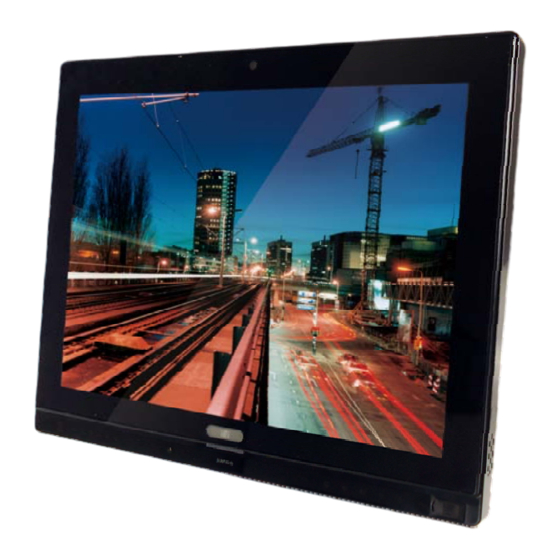
AFL2-15A-H61 1.1 Overview Figure 1-1: AFL2-15A-H61 Flat Bezel Panel PC The AFL2-15A-H61 is a 2nd Generation Intel® Core™ i7/ i5/ i3 or Pentium® processor powered flat bezel panel PC with a rich variety of functions and peripherals. The AFL2-15A-H61 is designed for easy and simplified integration into kiosk and point-of-sales (POS) applications. -
Page 21: Model Variations
Type K thermalcouple temperature Optional EM or Mifare RFID reader 1.1.3 Light Fanless Technology Design AFL2-15A-H61 series panel PCs are designed with light fanless technology. The light fanless technology utilizes type K thermocouple temperature sensor to detect environment Page 3... -
Page 22: External Overview
AFL2-15A-H61 temperature and control fan operation to enhance system stability and remote environment control. When the environment temperature is lower than default temperature setting, the fan will turn off, showing the advantage of quiet and dust free from fanless mode. While the environment temperature is higher, the smart fan will turn on to speed up heat emission. -
Page 23: Led Indicators
AFL2-15A-H61 1.2.1.1 LED Indicators There are several LED indicators located along the bottom of the LCD screen (Figure 1-3). Figure 1-3: LED Indicators The descriptions of each LED indicator are listed below. LED Indicator Description Off: power cord not attached or power supply failure Power Blinking amber: the system is connected to a power source and is ready to be turned on. -
Page 24: Table 1-2: Led Indicators
AFL2-15A-H61 LED Indicator Description On: the Bluetooth module is enabled Bluetooth Off: the Bluetooth module is disabled. Controlled by the BIOS. See Section 4.5.2 On: the auto-dimming function is enabled Auto-Dimming Off: the auto-dimming function is disabled. Hold down Fn key for 3 seconds to enable/disable auto-dimming function. -
Page 25: Figure 1-4: Ledlight Utility
AFL2-15A-H61 The LED indicator brightness can be adjusted via a utility called LedLight. To use the LedLight utility to control indicator brightness, follow the steps below. Step 1: Double click LedLight.exe to open the utility. Figure 1-4: LedLight Utility Step 2: The user can use either auto mode or manual mode to control LED brightness: Auto mode: select Auto to have the LedLight adjust LED indicator brightness to the pre-set settings. -
Page 26: Function Keys
AFL2-15A-H61 1.2.1.2 Function Keys The function keys are located under the bottom right hand corner of the LCD screen (Figure 1-4). Figure 1-6: Function Keys The function keys are described in Table 1-3: Key Combination Function Key Description Hold down Fn key for 3 seconds to enable/disable auto-dimming function. -
Page 27: Rear Panel
AFL2-15A-H61 1.2.2 Rear Panel The rear panel provides access to retention screw holes that support VESA mounting. The HDD bay and CF slot are protected by the HDD cover. Refer to Figure 1-5. Figure 1-7: Rear View 1.2.3 Bottom Panel The bottom panel of the AFL2-15A-H61 has the following connectors and switches (Figure 1-6): 1 x AT/ATX switch... -
Page 28: Side Panels
AFL2-15A-H61 Figure 1-8: Bottom Panel 1.2.4 Side Panels The side panels of the AFL2-15A-H61 have the following features (Figure 1-9): 2 x Audio jacks (Line-out, Mic-in) 1 x RJ-45 LAN connector 1 x USB 2.0 connector 1 x Temperature sensor (left side panel) Page 10... -
Page 29: Dimensions
AFL2-15A-H61 Figure 1-9: Side Panels 1.3 Dimensions The AFL2-15A-H61 dimensions are shown below. Width: 363.2 mm Height: 305.1 mm Depth: 58.8 mm Page 11... -
Page 30: Internal Overview
AFL2-15A-H61 Figure 1-10: AFL2-15A-H61 Dimensions (mm) 1.4 Internal Overview The AFL2-15A-H61 has the following components installed internally: 1 x Motherboard 2 x 2.0 GB 1333 MHz DDR3 SO-DIMMs 1 x 802.11 b/g/n wireless LAN module Page 12... -
Page 31: System Specifications
AFL2-15A-H61 1.5 System Specifications The technical specifications for the AFL2-15A-H61 systems are listed in Table 1-4. Specification AFL2-15A-H61 LCD Size 15" (4:3) Max. Resolution 1024 (W) x 768 (H) Brightness (cd/m Contrast Ratio 700:1 LCD Color 16.2M Pixel Pitch (H x V) (mm) 0.297(H) x 0.297 (V) Viewing Angle (H-V) 160°... -
Page 32: Table 1-4: System Specifications
AFL2-15A-H61 Weight (N/G) 5.2 kg / 7.3 kg Dimensions (W x H x D) (mm) 363.2 x 305.1 x 58.8 Operating Temperature -20ºC ~ 50ºC Storage Temperature -20ºC ~ 60ºC Humidity 10% ~ 95% (no-condensing) IP level IP 64 compliant front panel Power Supply 90W power adapter Input: 100V AC ~ 240V AC @ 50 / 60 Hz... -
Page 33: Unpacking
AFL2-15A-H61 Chapter Unpacking Page 15... -
Page 34: Unpacking
AFL2-15A-H61 2.1 Unpacking To unpack the flat bezel panel PC, follow the steps below: WARNING! The front side LCD screen has a protective plastic cover stuck to the screen. Only remove the plastic cover after the flat bezel panel PC has been properly installed. - Page 35 AFL2-15A-H61 Power adapter (P/N: 63040-010090-020-RS) Power cord (P/N: 32702-000401-100-RS) Power transfer cord (P/N: 32702-000300-100-RS) RJ-45 to DB-9 COM Port Cable (P/N: 32005-000200-200-RS) OSD Remote Control (P/N: 7Z000-SLPCB005-RS) Temperature sensor cable (P/N: 32133-004300-100-RS) Pen for resistive touchscreen (P/N: 43125-0002C0-00-RS) M3 screw pack (P/N: 44013-030041-RS) M4 screw pack (P/N: 44033-040061-RS)
- Page 36 AFL2-15A-H61 Optional Wall mounting kit (P/N: AFLWK-19/AFLWK-19B) (P/N: ARM-11-RS/ARM-31-RS) Stand (P/N: STAND-A19/ STAND-B19/ STAND-C19/ STAND-210-R11) Hybrid Card Reader (P/N: AFL2P-12AMSI-U-R10) Magnetic Stripe Reader (P/N: AFL2P-12AMSR-U-R10) Bluetooth Module Kit (P/N: AFL2-BT-KIT01-R11) OS: Win CE 6.0 (128MB CF Card) (P/N: AFL2CF-15A-H61-CE060-128M-R10) OS: Win XPE (2GB CF Card) (P/N: AFL2CF-15A-H61-XPE-2G-R10) OS: Win XPE (4GB CF Card) (P/N: AFL2CF-15A-H61-XPE-4G-R10)
- Page 37 AFL2-15A-H61 OS: Linux (2GB CF Card) (P/N: AFL2CF-15A-H61-LNX-2G-R10) OS: Win 7 Embedded (4GB CF Card) (P/N: AFL2CF-15A-H61-WES7P-4G-R10 AFL2CF-15A-H61-WES7E-4G-R10) If any of these items are missing or damaged, contact the distributor or sales representative immediately. Page 19...
-
Page 38: Installation
AFL2-15A-H61 Chapter Installation Page 20... -
Page 39: Anti-Static Precautions
AFL2-15A-H61 3.1 Anti-static Precautions WARNING: Failure to take ESD precautions during the maintenance of the AFL2-15A-H61 may result in permanent damage to the AFL2-15A-H61 and severe injury to the user. Electrostatic discharge (ESD) can cause serious damage to electronic components, including the AFL2-15A-H61. -
Page 40: Installation And Configuration Steps
AFL2-15A-H61 Anti-static Discharge: If a user open the rear panel of the flat bezel panel PC, to configure the jumpers or plug in added peripheral devices, ground themselves first and wear and anti-static wristband. 3.3 Installation and Configuration Steps The following installation steps must be followed. Step 1: Unpack the flat bezel panel PC. -
Page 41: Figure 3-1: Hdd Cover Retention Screws
AFL2-15A-H61 Figure 3-1: HDD Cover Retention Screws Step 2: Remove the HDD cover from the device. Step 3: Loosen the captive screw to release the HDD bracket from the chassis. Slide the HDD bracket out of the device as shown (Figure 3-2). Figure 3-2: HDD Bracket Removal Step 4: Insert an HDD into the bracket as shown (Figure 3-3). -
Page 42: Figure 3-3: Inserting The Hdd
AFL2-15A-H61 Figure 3-3: Inserting the HDD Step 5: Secure the HDD to the bracket using four (4) retention screws (two screws on each side) (Figure 3-4). Figure 3-4: Securing the HDD Step 6: Slide the HDD module back into the device. Step 7: Tighten the captive screw. -
Page 43: Cf Card Installation
AFL2-15A-H61 3.5 CF Card Installation The AFL2-15A-H61 has one CF Type II slot under the HDD bay. To install the CF card, follow the instructions below. Step 1: Remove two (2) retention screws from the HDD cover (Figure 3-1). Step 2: Remove the HDD cover from the device. -
Page 44: Rfid Reader Installation (Optional)
AFL2-15A-H61 3.6 RFID Reader Installation (Optional) An optional RFID reader can be installed in the AFL2-15A-H61. To install the RFID reader, follow the instructions below. Step 1: Remove a total of ten (10) retention screws from the back cover (Figure 3-7). Figure 3-7: Back Cover Retention Screws Step 2: Remove the six (6) retention screws securing the internal aluminum cover to the... -
Page 45: Figure 3-9: Rfid Reader Module Installation
AFL2-15A-H61 Step 3: Install the RFID reader module in the location shown in Figure 3-9 by two retention screws. Figure 3-9: RFID Reader Module Installation Step 4: Connect the RFID module to the RFID connector on the main board (Figure 3-10). -
Page 46: At/Atx Mode Selection
AFL2-15A-H61 Step 6: Replace the internal cover and back cover using previously removed retention screws. Step 0: 3.7 AT/ATX Mode Selection AT or ATX power mode can be used on the AFL2-15A-H61. The selection is made through an AT/ATX switch located on the bottom panel. To select AT mode or ATX mode, follow the steps below. -
Page 47: Clear Cmos
AFL2-15A-H61 broadcasting time for each panel PC can be set individually and controlled remotely. Other possible application includes Security surveillance Point-of-Sale (POS) Advertising terminal 3.8 Clear CMOS If the AFL2-15A-H61 fails to boot due to improper BIOS settings, the clear CMOS switch clears the CMOS data and resets the system BIOS information. -
Page 48: Powering On The System
AFL2-15A-H61 Step 2: Press the reset button. Step 0: 3.10 Powering On the System To power on the system, follow the steps below: Step 1: Locate the Function and Brightness Up function keys. See Section 1.2.1.2. Step 2: Hold down the Function and Brightness Up buttons for three seconds to power on the system. -
Page 49: Wall Mounting
AFL2-15A-H61 3.12.1 Wall Mounting To mount the flat bezel panel PC onto the wall, please follow the steps below. Step 1: Select the location on the wall for the wall-mounting bracket. Step 2: Carefully mark the locations of the four screw holes in the bracket on the wall. Step 3: Drill four pilot holes at the marked locations on the wall for the bracket retention screws. - Page 50 AFL2-15A-H61 Step 6: Insert the four monitor mounting screws provided in the wall mount kit into the four screw holes on the real panel of the flat bezel panel PC and tighten until the screw shank is secured against the rear panel (Figure 3-15). WARNING: Please use the M4 screws provided in the wall mount kit for the rear panel.
-
Page 51: Figure 3-15: Chassis Support Screws
AFL2-15A-H61 Figure 3-15: Chassis Support Screws Step 9: Secure the panel PC by fastening the retention screw of the wall-mounting bracket. (Figure 3-16). Figure 3-16: Secure the Panel PC Page 33... -
Page 52: Arm Mounting
AFL2-15A-H61 3.12.2 Arm Mounting The AFL2-15A-H61 is VESA (Video Electronics Standards Association) compliant and can be mounted on an arm with a 100mm interface pad. To mount the AFL2-15A-H61 on an arm, please follow the steps below. Step 1: The arm is a separately purchased item. Please correctly mount the arm onto the surface it uses as a base. -
Page 53: Stand Mounting
AFL2-15A-H61 Step 4: Secure the AFL2-15A-H61 to the interface pad by inserting four retention screws through the mounting arm interface pad and into the AFL2-15A-H61.S t e p 0 : Figure 3-18: Arm Mounting (ARM-11-RS) 3.12.3 Stand Mounting To mount the AFL2-15A-H61 using the stand mounting kit, please follow the steps below. Step 1: Locate the screw holes on the rear of the AFL2-15A-H61. -
Page 54: External Peripheral Device Connection
AFL2-15A-H61 Figure 3-19: Stand Mounting (Stand-A/Bxx) 3.13 External Peripheral Device Connection The following external peripheral devices can be connected to the external peripheral interface connectors. Audio devices HDMI devices RJ-45 Ethernet cable connector Serial port devices USB devices VGA monitor To install these devices, connect the corresponding cable connector from the actual device to the corresponding AFL2-15A-H61 external peripheral interface connector making sure the pins are properly aligned. -
Page 55: Audio Connection
AFL2-15A-H61 3.13.1 Audio Connection The audio jacks on the external audio connector enable the AFL2-15A-H61 to be connected to a stereo sound setup. To install the audio devices, follow the steps below. Step 1: Identify the audio plugs. The plugs on your home theater system or speakers may not match the colors on the rear panel. -
Page 56: Lan Connection
AFL2-15A-H61 Step 1: Locate the HDMI connector. The location is shown in Chapter 1. Step 2: Align the connector. Align the HDMI connector with the HDMI port. Make sure the orientation of the connector is correct. Figure 3-21: HDMI Connection Step 3: Insert the HDMI connector. -
Page 57: Serial Device Connection
AFL2-15A-H61 the RJ-45 connectors on the AFL2-15A-H61. See Figure 3-22. Figure 3-22: LAN Connection Step 3: Insert the LAN cable RJ-45 connector. Once aligned, gently insert the LAN cable RJ-45 connector into the external interface. 3.13.4 Serial Device Connection There are two external RS-232 DB-9 connectors and one RS-422/485 RJ-45 connector for serial device connection. -
Page 58: Serial Port Connection
AFL2-15A-H61 Step 2: Insert the serial connector. Insert the DB-9 connector of a serial device into the DB-9 connector on the bottom panel. See Figure 3-23. Figure 3-23: DB-9 Serial Port Connector Step 3: Secure the connector. Secure the serial device connector to the external interface by tightening the two retention screws on either side of the connector. -
Page 59: Type K Temperature Sensor Connection
AFL2-15A-H61 Figure 3-24: RJ-45 Serial Port Connector Step 4: Secure the connector. Secure the serial device connector to the external interface by tightening the two retention screws on either side of the connector. Step 0: 3.13.5 Type K Temperature Sensor Connection The AFL2-15A-H61 has a type K thermocouple connector on the bottom panel. -
Page 60: Usb Device Connection
AFL2-15A-H61 Figure 3-25: Type K Temperature Sensor Installation 3.13.6 USB Device Connection NOTE: User must install the USB 3.0 driver before connecting a USB device to the system or else the system may not recognize the connected device. There are three USB 2.0 connectors and two USB 3.0 connectors on the AFL2-15A-H61. To connect a USB device, please follow the instructions below. -
Page 61: Vga Monitor Connection
AFL2-15A-H61 Figure 3-26: USB Device Connection Step 3: Insert the device connector. Once aligned, gently insert the USB device connector into the onboard connector. Step 0: 3.13.7 VGA Monitor Connection The AFL2-15A-H61 has a single female DB-15 connector on the external peripheral interface panel. -
Page 62: Figure 3-27: Vga Connector
AFL2-15A-H61 Figure 3-27: VGA Connector Step 4: Secure the connector. Secure the DB-15 VGA connector from the VGA monitor to the external interface by tightening the two retention screws on either side of the connector. Page 44... -
Page 63: Bios Setup
AFL2-15A-H61 Chapter BIOS Setup Page 45... -
Page 64: Introduction
AFL2-15A-H61 4.1 Introduction A licensed copy of the BIOS is preprogrammed into the ROM BIOS. The BIOS setup program allows users to modify the basic system configuration. This chapter describes how to access the BIOS setup program and the configuration options that may be changed. -
Page 65: Getting Help
AFL2-15A-H61 F2 key Load previous values. F3 key Load optimized defaults F4 key Save changes and Exit BIOS Esc key Main Menu – Quit and do not save changes into CMOS Status Page Setup Menu and Option Page Setup Menu -- Exit current page and return to Main Menu Table 4-1: BIOS Navigation Keys 4.1.3 Getting Help... -
Page 66: Main
AFL2-15A-H61 4.2 Main The Main BIOS menu ( B IOS Menu 1) appears when the BIOS Setup program is entered. The Main menu gives an overview of the basic system information. Aptio Setup Utility – Copyright (C) 2011 American Megatrends, Inc. Main Advanced Chipset... -
Page 67: Advanced
AFL2-15A-H61 iWDD Version The iWDD Version displays the current iWDD version. The fields in iWDD Version cannot be changed. Memory Information The Memory Information lists a brief summary of the on-board memory. The fields in Memory Information cannot be changed. Total Memory: Displays the auto-detected system memory size and type. -
Page 68: Acpi Settings
AFL2-15A-H61 CPU Configuration SATA Configuration Intel TXT (LT) Configuration USB Configuration F81216 Super IO Configuration H/W Monitor Serial Port Console Redirection iEi Feature Aptio Setup Utility – Copyright (C) 2011 American Megatrends, Inc. Main Advanced Chipset Boot Security Save & Exit >... -
Page 69: Rtc Wake Settings
AFL2-15A-H61 Aptio Setup Utility – Copyright (C) 2011 American Megatrends, Inc. Advanced ACPI Settings Select the highest ACPI sleep state the system ACPI Sleep State [S1 (CPU Stop Clock)] will enter, when the SUSPEND button is pressed. ---------------------- : Select Screen ↑... -
Page 70: Bios Menu 4: Rtc Wake Settings
AFL2-15A-H61 Aptio Setup Utility – Copyright (C) 2011 American Megatrends, Inc. Advanced Wake system with Fixed Time [Disabled] Enable or disable System wake on alarm event. When enabled, System will wake on the dat::hr::min::sec specified ---------------------- : Select Screen ↑ ↓: Select Item Enter Select General Help Previous Values... -
Page 71: Trusted Computing
AFL2-15A-H61 4.3.3 Trusted Computing Use the Trusted Computing menu (BIOS Menu 5) to configure settings related to the Trusted Computing Group (TCG) Trusted Platform Module (TPM). Aptio Setup Utility – Copyright (C) 2011 American Megatrends, Inc. Advanced TPM Configuration Enables or Disables TPM TPM SUPPORT [Disable] support. -
Page 72: Cpu Information
AFL2-15A-H61 Aptio Setup Utility – Copyright (C) 2011 American Megatrends, Inc. Advanced CPU Configuration Socket specific CPU Information > CPU Information Hyper-threading [Enabled] ---------------------- Intel Virtualization Technology [Disabled] : Select Screen ↑ ↓: Select Item Enter Select +/-: Change Opt. General Help Previous Values Optimized Defaults... -
Page 73: Bios Menu 7: Cpu Configuration
AFL2-15A-H61 Aptio Setup Utility – Copyright (C) 2011 American Megatrends, Inc. Advanced Socket 0 CPU Information Intel(R) Core(TM) i3-2100T CPU @ 2.50GHz CPU Signature 206a7 ---------------------- Microcode Patch Max CPU Speed 2500 MHz Min CPU Speed 1600 MHz : Select Screen ↑... -
Page 74: Sata Configuration
AFL2-15A-H61 4.3.5 SATA Configuration Use the SATA Configuration menu (BIOS Menu 8) to change and/or set the configuration of the SATA devices installed in the system. Aptio Setup Utility – Copyright (C) 2011 American Megatrends, Inc. Advanced SATA Configuration (1) IDE Mode. (2) AHCI Mode. -
Page 75: Intel Txt (Lt) Configuration
AFL2-15A-H61 Compatible Configures the Serial-ATA controller to be in compatible EFAULT mode. In this mode, a SATA channel will replace one of the IDE channels. Serial-ATA Controller 1 [Enhanced] Use the Serial-ATA Controller 1 option to configure the Serial-ATA controller mode when the SATA mode is set to IDE Mode. -
Page 76: Usb Configuration
AFL2-15A-H61 4.3.7 USB Configuration Use the USB Configuration menu (BIOS Menu 10) to read USB configuration information and configure the USB settings. Aptio Setup Utility – Copyright (C) 2011 American Megatrends, Inc. Advanced USB Configuration USB Support Parameters USB Devices: 1 Drive, 3 Hubs --------------------- USB Support... - Page 77 AFL2-15A-H61 keyboard can control the system even when there is no USB driver loaded onto the system. Enabled Legacy USB support enabled EFAULT Disabled Legacy USB support disabled Auto Legacy USB support disabled if no USB devices are connected Generic STORAGE DEVICE 9454 [Auto] Use the Generic STORAGE DEVICE 9454 BIOS option to specify the type of emulation BIOS has to provide for the USB device.
-
Page 78: F81216 Super Io Configuration
AFL2-15A-H61 4.3.8 F81216 Super IO Configuration Use the F81216 Super IO Configuration menu (BIOS Menu 11) to set or change the configurations for the FDD controllers, parallel ports and serial ports. Aptio Setup Utility – Copyright (C) 2011 American Megatrends, Inc. Advanced F81216 Super IO Configuration Set Parameters of Serial... -
Page 79: Serial Port 1 Configuration
AFL2-15A-H61 4.3.8.1.1 Serial Port 1 Configuration Serial Port [Enabled] Use the Serial Port option to enable or disable the serial port. Disabled Disable the serial port Enable the serial port Enabled EFAULT Change Settings [Auto] Use the Change Settings option to change the serial port IO port address and interrupt address. -
Page 80: Serial Port 3 Configuration
AFL2-15A-H61 Enabled Enable the serial port EFAULT Change Settings [Auto] Use the Change Settings option to change the serial port IO port address and interrupt address. The serial port IO port address and interrupt Auto EFAULT address are automatically detected. IO=2F8h;... - Page 81 AFL2-15A-H61 Auto The serial port IO port address and interrupt EFAULT address are automatically detected. Serial Port I/O port address is 3E8h and the IO=3E8h; IRQ=7 interrupt address is IRQ7 IO=3F8h; IRQ=3, Serial Port I/O port address is 3F8h and the 4,5,6,7,10,11,12 interrupt address is IRQ3, 4, 5, 6, 7, 10, 11, 12 IO=2F8h;...
-
Page 82: H/W Monitor
AFL2-15A-H61 4.3.9 H/W Monitor The H/W Monitor menu (BIOS Menu 13) shows the operating temperature, fan speeds and system voltages. Aptio Setup Utility – Copyright (C) 2011 American Megatrends, Inc. Advanced CPU Temperature :+58 °C Environment Temperature 1 :+63 °C Environment Temperature 2 :+39 °C SYS Temperature... - Page 83 AFL2-15A-H61 Disabled Temperature of Fanless option can not be configured. Temperature of Fanless option can be configured. Enabled EFAULT Temperature Of Fanless [32 C] NOTE: If the Temperature of Fanless is enabled, the fan will only turn on when the Environment Temperature 1 reaches to the temperature set in the following Temperature of Fanless option.
-
Page 84: Serial Port Console Redirection
AFL2-15A-H61 24 C When the environment temperature 1 is lower than 24 C, the fan will be switched off. When the environment temperature 1 is lower than 28 28 C C, the fan will be switched off. 32 C When the environment temperature 1 is lower than 32 EFAULT C, the fan will be switched off. -
Page 85: Iei Feature
AFL2-15A-H61 Disabled Disabled the console redirection function EFAULT Enabled the console redirection function Enabled 4.4 iEi Feature Use the iEi Feature menu (BIOS Menu 15) to configure the auto recovery function. Aptio Setup Utility – Copyright (C) 2011 American Megatrends, Inc. Advanced iEi Feature Auto Recovery Function... -
Page 86: Chipset
AFL2-15A-H61 Micro SD Card [Enabled] Use the Micro SD Card option to enable or disable the microSD card slot on the front panel. Disabled microSD card slot is disabled EFAULT Enabled microSD card slot is enabled 4.5 Chipset Use the Chipset menu (BIOS Menu 16) to access the North Bridge, South Bridge, Integrated Graphics, and ME Subsystem configuration menus. -
Page 87: Northbridge Configuration
AFL2-15A-H61 4.5.1 Northbridge Configuration Use the North Bridge menu (BIOS Menu 17) to configure the Northbridge chipset. Aptio Setup Utility – Copyright (C) 2011 American Megatrends, Inc. Chipset Memory Information Select which graphics controller to use as the Total Memory 2048 MB (DDR3 1333) primary boot device. -
Page 88: Southbridge Configuration
AFL2-15A-H61 32 MB of memory used by internal graphics device 64 MB of memory used by internal graphics device 128M 128 MB of memory used by internal graphics device 256M 256 MB of memory used by internal graphics EFAULT device 512M 512 MB of memory used by internal graphics device... - Page 89 AFL2-15A-H61 Restore AC Power Loss [Last State] Use the Restore AC Power Loss BIOS option to specify what state the system returns to if there is a sudden loss of power to the system. Power Off The system remains turned off The system turns on Power On Last State...
- Page 90 AFL2-15A-H61 Disabled BT function disabled BT function enabled Enabled EFAULT RFID Function [Enabled] Use the RFID Function option to enable or disable the RFID function. Disabled RFID function disabled Enabled RFID function enabled EFAULT Auto Dimming Support [Disabled] Use the Auto Dimming Support option to enable or disable the auto dimming function. Disabled Auto dimming function disabled EFAULT...
-
Page 91: Integrated Graphics
AFL2-15A-H61 PCIe LAN PXE Boot [Disabled] Use the PCIe LAN PXE Boot option to enable or disable the boot option for the PCIe LAN PXE. Disabled Disables PCIe LAN PXE Boot option EFAULT Enables PCIe LAN PXE Boot option Enabled PCIe LAN Controller [Enabled] Use the PCIe LAN Controller option to enable or disable the PCI Express LAN controller. -
Page 92: Bios Menu 19: Integrated Graphics
AFL2-15A-H61 Aptio Setup Utility – Copyright (C) 2011 American Megatrends, Inc. Advanced Intel IGD SWSCI OpRegion Configuration Select DVMT Mode used by Internal Graphics DVMT Mode Select [DVMT Mode] Device. If Fixed Mode DVMT Memory [Maximum] selected, IGD Memory might need to be changed IGD - Boot Type [AUTO] to a larger value, for... -
Page 93: Me Subsystem
AFL2-15A-H61 IGD - Boot Type [AUTO] Use the IGD - Boot Type option to select the display device used by the system when it boots. For dual display support, select “Auto.” Configuration options are listed below. AUTO EFAULT LVDS HDMI 4.5.4 ME Subsystem Use the ME Subsystem menu (BIOS Menu 20) to configure the Intel®... -
Page 94: Boot
AFL2-15A-H61 Enter Enables user to enter MEBx setup MEBx Setup Unconfigure AMT/ME [Enabled] Use the Unconfigure AMT/ME option to perform AMT/ME unconfigure without password operation. Disable AMT/ME unconfigure Disabled Enabled Enable AMT/ME unconfigure EFAULT 4.6 Boot Use the Boot menu (BIOS Menu 21) to configure system boot options. Aptio Setup Utility –... - Page 95 AFL2-15A-H61 Allows the Number Lock on the keyboard to be EFAULT enabled automatically when the computer system boots up. This allows the immediate use of the 10-key numeric keypad located on the right side of the keyboard. To confirm this, the Number Lock LED light on the keyboard is lit.
-
Page 96: Security
AFL2-15A-H61 Disabled Disables boot option. Boot Option #2 [Generic STORAGE DE…] Use Boot Option #2 to enable or disable booting from the detected drive. Enables booting from the detected storage Generic EFAULT device. STORAGE DE… Disabled Disables boot option. Hard Drive BBS Priorities Use Hard Drive BBS Priorities option to set the system boot order. -
Page 97: Save & Exit
AFL2-15A-H61 User Password Use the User Password field to set or change a user password. 4.8 Save & Exit Use the Save & Exit menu (BIOS Menu 23) to load default BIOS values, optimal failsafe values and to save configuration changes. Aptio Setup Utility –... - Page 98 AFL2-15A-H61 Save as User Defaults Use the Save as User Defaults option to save the changes done so far as user defaults. Restore User Defaults Use the Restore User Defaults option to restore the user defaults to all the setup options. Page 80...
-
Page 99: Software Drivers
AFL2-15A-H61 Chapter Software Drivers Page 81... -
Page 100: Available Software Drivers
AFL2-15A-H61 5.1 Available Software Drivers NOTE: The content of the CD may vary throughout the life cycle of the product and is subject to change without prior notice. Visit the IEI website or contact technical support for the latest updates. The following drivers can be installed on the system: Chipset Graphic... -
Page 101: Chipset Driver Installation
AFL2-15A-H61 Figure 5-1: Drivers 5.3 Chipset Driver Installation To install the chipset driver, please do the following. Step 1: Access the driver list. (See Section 5.2) Step 2: Click “Chipset.” Step 3: Locate the setup file and double click on it. Step 4: The setup files are extracted as shown in Figure 5-2. -
Page 102: Figure 5-2: Chipset Driver Screen
AFL2-15A-H61 Figure 5-2: Chipset Driver Screen Step 5: When the setup files are completely extracted the Welcome Screen in Figure 5-3 appears. Step 6: Click Next to continue. Figure 5-3: Chipset Driver Welcome Screen Step 7: The license agreement in Figure 5-4 appears. Page 84... -
Page 103: Figure 5-4: Chipset Driver License Agreement
AFL2-15A-H61 Step 8: Read the License Agreement. Step 9: Click Yes to continue. Figure 5-4: Chipset Driver License Agreement Step 10: The Read Me file in Figure 5-5 appears. Step 11: Click Next to continue. Page 85... -
Page 104: Figure 5-5: Chipset Driver Read Me File
AFL2-15A-H61 Figure 5-5: Chipset Driver Read Me File Step 12: Setup Operations are performed as shown in Figure 5-6. Step 13: Once the Setup Operations are complete, click Next to continue. Figure 5-6: Chipset Driver Setup Operations Step 14: The Finish screen in Figure 5-7 appears. Page 86... -
Page 105: Graphics Driver Installation
AFL2-15A-H61 Step 15: Select “Yes, I want to restart this computer now” and click Finish.Step 0: Figure 5-7: Chipset Driver Installation Finish Screen 5.4 Graphics Driver Installation To install the Graphics driver, please do the following. Step 1: Access the driver list. (See Section 5.2) Step 2: Click “VGA”... -
Page 106: Figure 5-8: Graphics Driver Read Me File
AFL2-15A-H61 Figure 5-8: Graphics Driver Read Me File Step 6: The installation files are extracted. See Figure 5-9. Step 7: Click Next to continue. Figure 5-9: Graphics Driver Setup Files Extracted Step 8: The Welcome Screen in Figure 5-10 appears. Step 9: Click Next to continue. -
Page 107: Figure 5-10: Graphics Driver Welcome Screen
AFL2-15A-H61 Figure 5-10: Graphics Driver Welcome Screen Step 10: The License Agreement in Figure 5-11 appears. Step 11: Click Yes to accept the agreement and continue. Figure 5-11: Graphics Driver License Agreement Step 12: The Read Me file in Figure 5-12 appears. Step 13: Click Next to continue. -
Page 108: Figure 5-12: Graphics Driver Read Me File
AFL2-15A-H61 Figure 5-12: Graphics Driver Read Me File Step 14: Setup Operations are performed as shown in Figure 5-13. Step 15: Once the Setup Operations are complete, click Next to continue. Figure 5-13: Graphics Driver Setup Operations Step 16: The Finish screen in Figure 5-14 appears. Step 17: Select “Yes, I want to restart this computer now”... -
Page 109: Lan Driver Installation
AFL2-15A-H61 Figure 5-14: Graphics Driver Installation Finish Screen 5.5 LAN Driver Installation To install the LAN driver, please do the following. Step 1: Access the driver list. (See Section 5.2) Step 2: Click “LAN” and select the folder which corresponds to the operating system. Step 3: Double click the setup file. -
Page 110: Figure 5-15: Lan Driver Welcome Screen
AFL2-15A-H61 Figure 5-15: LAN Driver Welcome Screen Step 5: Click Next to continue. Step 6: The Ready to Install the Program Screen in Figure 5-16 appears. Step 7: Click Install to proceed with the installation. Figure 5-16: LAN Driver Ready to Install Screen Step 8: The program begins to install. -
Page 111: Audio Driver Installation
AFL2-15A-H61 Figure 5-17: LAN Driver Setup Status Screen Step 10: When the driver installation is complete, the screen in Figure 5-18 appears. Step 11: Click Finish to exit. Figure 5-18: LAN Driver Installation Complete 5.6 Audio Driver Installation To install the audio driver, please do the following. Step 1: Access the driver list. -
Page 112: Figure 5-19: Audio Driver Welcome Screen
AFL2-15A-H61 Step 2: Click “Audio” and select the folder which corresponds to your operating system. Step 3: Double click the setup file. Step 4: The Audio Driver Welcome Screen in Figure 5-19 appears. Step 5: Click Next to continue. Figure 5-19: Audio Driver Welcome Screen Step 6: The audio driver installation begins. -
Page 113: Figure 5-20: Audio Driver Installation
AFL2-15A-H61 Figure 5-20: Audio Driver Installation Step 7: When the installation is complete, the screen in Figure 5-21 appears. Step 8: Select “Yes, I want to restart my computer now” and click Finish. Step 0: Figure 5-21: Audio Driver Installation Complete Page 95... -
Page 114: Touchscreen Driver
AFL2-15A-H61 5.7 Touchscreen Driver To install the touch panel software driver, please follow the steps below. Step 1: Access the driver list. (See Section 5.2) Step 2: Click “Touch Screen.” Step 3: Locate the setup file and double click on it. Step 4: A Welcome Screen appears (Figure 5-22). -
Page 115: Figure 5-23: Touchscreen Driver License Agreement
AFL2-15A-H61 Figure 5-23: Touchscreen Driver License Agreement Step 8: Browse for an install location or use the one suggested (Figure 5-24). Step 9: Click I to continue. NSTALL Figure 5-24: Touchscreen Driver Choose Install Location Step 10: The Install screen appears and displays the progress of the installation (Figure 5-25). -
Page 116: Figure 5-25: Touchscreen Driver Installation Screen
AFL2-15A-H61 Step 11: Click N to continue. Figure 5-25: Touchscreen Driver Installation Screen Step 12: When the installation is complete, click F to exit setup. (Figure 5-26). INISH Figure 5-26: Touchscreen Driver Update Complete Page 98... -
Page 117: Calibrating The Touchscreen
AFL2-15A-H61 5.7.1 Calibrating the Touchscreen To calibrate the touchscreen cursor with the motion of the touchscreen pen (or finger), please follow the steps below: Step 1: Make sure the touchscreen driver is properly installed. Step 2: Locate the PenMount Monitor icon in the bottom right corner of the screen. Figure 5-27: PenMount Monitor Icon Step 3: Click the icon. -
Page 118: Figure 5-29: Configuration Screen
AFL2-15A-H61 Figure 5-29: Configuration Screen Step 6: Double click the PenMount 9000 icon as shown in Figure 5-29. Step 7: The calibration initiation screen in Figure 5-30 appears. Step 8: Select the Standard Calibration button as shown in Figure 5-30. Figure 5-30: Calibration Initiation Screen Step 9: The calibration screen in is shown. -
Page 119: Wi-Fi Driver Installation
AFL2-15A-H61 Figure 5-31: Calibration Screen Step 10: Follow the instructions. The user is asked touch the screen at five specified points after which the screen is calibrated. Step 0: 5.8 Wi-Fi Driver Installation To install the wireless LAN driver, please follow the steps below. Step 1: Access the driver list. -
Page 120: Figure 5-33: Setup Type
AFL2-15A-H61 Step 4: Accept the conditions of the license agreement and click NEXT to continue. Step 5: The Setup Type screen in Figure 5-33 appears. Figure 5-33: Setup Type Step 6: Select “Install driver and Ralink WLAN Utility” and click NEXT to continue. Step 7: The Configuration Tool screen in Figure 5-34 appears. -
Page 121: Figure 5-34: Configuration Tool
AFL2-15A-H61 Figure 5-34: Configuration Tool Select “Ralink Configuration Tool”and click NEXT to continue. Step 8: Step 9: The Ready to Install the Program screen in Figure 5-35 appears. Figure 5-35: Ready to Install the Program Step 10: Click Install to proceed with the installation. Page 103... -
Page 122: Figure 5-36: Setup Status
AFL2-15A-H61 Step 11: The Setup Status screen in Figure 5-36 appears and displays the progress of the installation. Figure 5-36: Setup Status Step 12: When the driver installation is complete, the screen in Figure 5-37 appears. Figure 5-37: Installation Complete Page 104... -
Page 123: Usb 3.0 Driver Installation
AFL2-15A-H61 Step 13: Click FINISH to complete installation. 5.9 USB 3.0 Driver Installation To install the touch panel software driver, please follow the steps below. Step 1: Access the driver list. (See Section 5.2) Step 2: Click “USB 3.0”. Step 3: Locate the setup file and double click on it. -
Page 124: Figure 5-39: Usb 3.0 Driver License Agreement
AFL2-15A-H61 Figure 5-39: USB 3.0 Driver License Agreement Step 8: Click N to continue. Figure 5-40: USB 3.0 Driver Installation Step 9: The Install screen appears and displays the progress of the installation. Step 10: When the installation is complete, click Finish to exit setup. (Figure 5-41). Page 106... -
Page 125: Figure 5-41: Usb 3.0 Driver Update Complete
AFL2-15A-H61 Figure 5-41: USB 3.0 Driver Update Complete Page 107... -
Page 126: System Monitoring: Icmc
AFL2-15A-H61 Chapter System Monitoring: iCMC Page 108... -
Page 127: Iei Cooling Management Console (Icmc)
AFL2-15A-H61 6.1 IEI Cooling Management Console (iCMC) The iCMC system cooling management console tracks system and CPU temperatures, frequency, cooling fan speeds, and allows users to configure light fanless settings. The iCMC quickly captures and reports system conditions to ensure operators can prevent system damage. -
Page 128: Figure 6-2: Select Installation Folder
AFL2-15A-H61 Step 4: Select a folder for Cooling Management Console installation in Figure 6-2. Click Next to continue. Figure 6-2: Select Installation Folder Step 5: The following screen appears. Click Next to confirm the installation. Figure 6-3: Confirm Installation Step 6: The system starts installing the Cooling Management Console. -
Page 129: Figure 6-4: Installation Complete
AFL2-15A-H61 Step 7: When the Cooling Management Console is successfully installed, the following window appears. Click Close to exit. Figure 6-4: Installation Complete Step 8: The confirmation screen offers the option of restarting the system now or later. For the settings to take effect, the system must be restarted. Click Yes to restart the system. -
Page 130: Icmc Overview
AFL2-15A-H61 Figure 6-6: Cooling Management Console Icon 6.2 iCMC Overview Figure 6-7 shows the iCMC interface. The iCMC interface is consisted of two panels: information panel (left) and chart panel (right). The chart panel can be hidden by selecting Chart visible option to “Off”. The following sections describe the two panels in detail. Figure 6-7: iCMC 6.2.1 Information Panel Figure 6-8 shows the information panel interface. -
Page 131: Figure 6-8: Icmc Information Panel
AFL2-15A-H61 Figure 6-8: iCMC Information Panel Temperature The current CPU temperature. System 1 The current system temperature. System 2 The current system temperature. Environment 1 The current environment temperature detected by the temperature sensor on the system. Environment 2 The current environment temperature detected by the temperature sensor on the system. -
Page 132: Table 6-1: Icmc Information Panel Description
AFL2-15A-H61 The system fan speed. “0” indicates the fan is off. System Info CPU Frequency The CPU frequency parameters. CPU Loading The CPU loading parameters. CPU Type The brand name of the CPU being used in the system. Light Fanless Settings BIOS Overwrite Use this option to determine either to follow the BIOS setting or the iCMC setting for the light fanless operation. -
Page 133: Chart Panel
AFL2-15A-H61 6.2.2 Chart Panel Figure 6-9 shows the chart panel interface. The line chart is used to visualize the system data listed in the information panel. The following information is displayed in different color lines: Green: CPU frequency Pink: CPU temperature Blue: System temperature 1 Yellow: Environment temperature 1 Red: Environment temperature 2... -
Page 134: Figure 6-10: Icmc - Time Interval Adjustment
AFL2-15A-H61 The user can adjust the time interval between sampling by selecting the options in the Sampling drop down menu (see Figure 6-10). The x-axis of the line chart (Time in seconds) will change according to the adjustment. Figure 6-10: iCMC – Time Interval Adjustment Page 116... -
Page 135: System Maintenance
AFL2-15A-H61 Chapter System Maintenance Page 117... -
Page 136: System Maintenance Introduction
AFL2-15A-H61 7.1 System Maintenance Introduction If the components of the AFL2-15A-H61 fail they must be replaced. Components that can be replaced include: SO-DIMM module WLAN module Please contact the system reseller or vendor to purchase the replacement parts. Back cover removal instructions for the AFL2-15A-H61 are described below. 7.2 Anti-static Precautions WARNING: Failure to take ESD precautions during the maintenance of the... -
Page 137: Turn Off The Power
AFL2-15A-H61 7.3 Turn off the Power WARNING: Failing to turn off the system before opening it can cause permanent damage to the system and serious or fatal injury to the user. Before any maintenance procedures are carried out on the system, make sure the system is turned off. -
Page 138: Removing The Internal Aluminum Cover
AFL2-15A-H61 Step 3: Remove a total of ten (10) retention screws from the back cover (Figure 7-1). Figure 7-1: Back Cover Retention Screws Step 4: Carefully separate the back cover from the chassis and lift the cover clear of the device Step 0: 7.4.2 Removing the Internal Aluminum Cover... -
Page 139: Replacing Components
AFL2-15A-H61 Figure 7-2: Internal Cover Retention Screws Step 2: Lift the aluminum cover off the AFL2-15A-H61. Step 3: The internal parts will all be viewable. Figure 7-3: Internal Components 7.5 Replacing Components 7.5.1 Memory Module Replacement The flat bezel panel PC is preinstalled with two 2.0 GB DDR3 memory module. If the memory module fails, follow the instructions below to replace the memory module. -
Page 140: Figure 7-4: Ddr So-Dimm Module Installation
AFL2-15A-H61 Step 1: Follow all anti-static procedures. See Section 7.2. Step 2: Turn off the power. See Section 7.3. Step 3: Remove the back cover. See Section 7.4.1 above. Step 4: Remove the internal aluminum back cover. See Section 7.4.2 above. Step 5: Locate the DDR3 SO-DIMM on the motherboard. -
Page 141: Wlan Card Replacement
AFL2-15A-H61 Step 12: Replace the back cover and secure it using ten (10) previously removed retention screws. Step 0: 7.5.2 WLAN Card Replacement The AFL2-15A-H61 has one WLAN card slot. To replace the WLAN card, follow the instructions below. Step 1: Follow all anti-static procedures. -
Page 142: Figure 7-6: Releasing The Wlan Card
AFL2-15A-H61 Figure 7-6: Releasing the WLAN Card Step 8: Grasp the WLAN card by the edges and carefully pull it out of the socket (Figure 7-7). Figure 7-7: Removing the WLAN card Step 9: Install a new WLAN card by inserting the card into the slot at an angle Step 10: Push the WLAN card down until the spring retainer clips lock into place. -
Page 143: Reinstalling The Covers
AFL2-15A-H61 Figure 7-8: Attaching the Antennas Step 12: Replace the internal aluminum cover and secure it to the chassis using six (6) retention screws. Step 13: Replace the back cover and secure it using ten (10) previously removed retention screws. Step 0: 7.6 Reinstalling the Covers WARNING:... -
Page 144: Interface Connectors
AFL2-15A-H61 Chapter Interface Connectors Page 126... -
Page 145: Peripheral Interface Connectors
AFL2-15A-H61 8.1 Peripheral Interface Connectors The AFL2-15A-H61 panel PC motherboard comes with a number of peripheral interface connectors and configuration jumpers. The connector locations are shown in Figure 8-1. The Pin 1 locations of the on-board connectors are also indicated in the diagram below. The connector pinouts for these connectors are listed in the following sections. -
Page 146: Internal Peripheral Connectors
AFL2-15A-H61 8.2 Internal Peripheral Connectors Internal peripheral connectors are found on the motherboard and are only accessible when the motherboard is outside of the chassis. The table below shows a list of the peripheral interface connectors on the AFL2MB-15A. Pinouts of these connectors can be found in the following sections. -
Page 147: Auto-Dimming Connector (Jp7)
AFL2-15A-H61 Connector Type Label SATA power connector 2-pin wafer SO-DIMM connectors SO-DIMM connector DIMM1, DIMM2 Speaker connector 4-pin wafer SPK_CN13 SPI Flash connector 6-pin wafer JSPI1 SPI Flash connector (EC) 6-pin wafer JSPI2 Touch panel connector 9-pin wafer TPM connector 20-pin header TPM1 Type K thermocouple connector... -
Page 148: Bluetooth Usb Connector (Bluetooth1)
AFL2-15A-H61 8.2.3 Bluetooth USB Connector (BLUETOOTH1) PIN NO. DESCRIPTION -DATA9 +DATA9 Table 8-4: Bluetooth USB Connector (BLUETOOTH1) Pinouts 8.2.4 EC Debug Connector (CN15) PIN NO. DESCRIPTION PIN NO. DESCRIPTION EC_EPP_STB# EC_EPP_AFD# EC_EPP_PD0 EC_EPP_ERR# EC_EPP_PD1 EC_EPP_INIT# EC_EPP_PD2 EC_EPP_SLIN# EC_EPP_PD3 EC_EPP_PD4 EC_EPP_ACK# EC_EPP_PD5 EC_EPP_BUSY EC_EPP_PD6... -
Page 149: Hdd Connector (Jsata3)
AFL2-15A-H61 8.2.6 HDD Connector (JSATA3) PIN NO. DESCRIPTION PIN NO. DESCRIPTION +V12S +V12S +V5S SATA20_PRX_C_DTX_P3 +V5S SATA20_PRX_C_DTX_N3 +V5S +V5S SATA20_PRX_C_DRX_P3 SATA20_PRX_C_DRX_N3 +V3.3S +V3.3S Table 8-7: HDD Connector (JSTAT3) Pinouts 8.2.7 Hot Key LED Connector (HOTKEYLEDCN1) PIN NO. DESCRIPTION PIN NO. DESCRIPTION KEYLED1 KEYLED2... -
Page 150: Led Indicator Connector (Ledcn1)
AFL2-15A-H61 8.2.9 LED Indicator Connector (LEDCN1) PIN NO. DESCRIPTION PIN NO. DESCRIPTION AUDIO_LED# PWRLED01# MIC_LED# PWRLED02# CPU_LED02# AT_LED# CPU_LED01# ATX_LED# AD_LED# +V3.3S WiFi_LED# +V3.3S BT_LED# +V3.3A_EC VCC_RFID GROUND Table 8-10: LED Indicator Connector (LEDCN1) Pinouts 8.2.10 Logo LED Connector (LOGO_LED) PIN NO. -
Page 151: Lvds Backlight Connector (Inverter1)
AFL2-15A-H61 A7P_C A7M_C Table 8-12: LVDS Connector (LVDS1) Pinouts 8.2.12 LVDS Backlight Connector (INVERTER1) PIN NO. DESCRIPTION BKL_POWER BKL_POWER ENABKL BRIGHTNESS Table 8-13: LVDS Backlight Connector (INVERTER1) Pinouts 8.2.13 Microphone Connector (DMIC1) PIN NO. DESCRIPTION DMIC_CLK DMIC _DATA VCC3 Table 8-14: Microphone Connector (DMIC1) Pinouts Page 133... -
Page 152: Mini Usb Connector (Minusb1)
AFL2-15A-H61 8.2.14 Mini USB Connector (MINUSB1) PIN NO. DESCRIPTION -DATA8 +DATA8 3VCC Table 8-15: Mini USB Connector (MINUSB1) Pinouts 8.2.15 Mini USB Connector (MINUSB2) PIN NO. DESCRIPTION -DATA4 +DATA4 Table 8-16: Mini USB Connector (MINUSB2) Pinouts 8.2.16 Power Button Connector (PW_BT1) PIN NO. -
Page 153: Rfid Usb Connector (Rfidusb1)
AFL2-15A-H61 8.2.17 RFID USB Connector (RFIDUSB1) PIN NO. DESCRIPTION -DATA5 +DATA5 Table 8-18: RFID USB Connector (RFID_USB1) Pinouts 8.2.18 SATA Connector (SATA1) PIN NO. DESCRIPTION Table 8-19: SATA Connector (SATA1) Pinouts 8.2.19 SATA Power Connector (CN8) PIN NO. DESCRIPTION +V5S Table 8-20: SATA Power Connector (CN8) Pinouts Page 135... -
Page 154: Speaker Connector (Spk_Cn13)
AFL2-15A-H61 8.2.20 Speaker Connector (SPK_CN13) PIN NO. DESCRIPTION SPK_OUT_P_L SPK_OUT_N_L SPK_OUT_N_R SPK_OUT_P_R Table 8-21: Speaker Connector (SPK_CN13) Pinouts 8.2.21 SPI Flash Connector (JSPI1) PIN NO. DESCRIPTION SPI_VCC SPI_CS#0_CN SPI_SO0_CN SPI_CLK0_CN SPI_SI0_CN Table 8-22: SPI Flash Connector (JSPI1) Pinouts 8.2.22 EC SPI Flash Connector (JSPI2) PIN NO. -
Page 155: Touch Panel Connector (Ts1)
AFL2-15A-H61 8.2.23 Touch Panel Connector (TS1) PIN NO. DESCRIPTION SENSE Table 8-24: Touch Panel Connector (TS1) Pinouts 8.2.24 TPM Connector (TPM1) PIN NO. DESCRIPTION PIN NO. DESCRIPTION TPMPCLK LPC_FRAME# BUF_PLT_RST# +V5S LPC_AD3 LPC_AD2 +V3.3S LPC_AD1 LPC_AD0 SMBCLK_MAIN SMBDATA_MAIN +V3.3A INT_SERIRQ PM_CLKRUN# PM_SUS_STAT# SIO_DRQ#0... -
Page 156: Type K Thermocouple Connector (Cn13, Cn14)
AFL2-15A-H61 8.2.25 Type K Thermocouple Connector (CN13, CN14) PIN NO. DESCRIPTION Table 8-26: Type K Thermocouple Connector (CN13, CN14) Pinouts 8.2.26 Webcam Connector (WEBCAMER1) PIN NO. DESCRIPTION -DATA10 +DATA10 Table 8-27: Webcam Connector (WEBCAMER1) Pinouts 8.3 External Interface Panel Connectors The table below lists the rear panel connectors on the AFL2MB-15A motherboard. -
Page 157: Audio Mic-In Jack (Mic1)
AFL2-15A-H61 Connector Type Label VGA connector DB-15 VGA1 Table 8-28: Rear Panel Connectors 8.3.1 Audio Mic-in Jack (MIC1) PIN NO. DESCRIPTION PIN NO. DESCRIPTION MIC1_JD LMIC1-CONN-R LMIC1-CONN-L Table 8-29: Audio Mic-in Jack (MIC1) Pinouts 8.3.2 Audio Lline-out Jack (LINE_OUT1) PIN NO. DESCRIPTION PIN NO. -
Page 158: Hdmi Connector (Hdmi1)
AFL2-15A-H61 8.3.4 HDMI Connector (HDMI1) PIN NO. DESCRIPTION PIN NO. DESCRIPTION HDMI_TMDS_C_DATA2 HDMI_TMDS_C_DATA2# HDMI_TMDS_C_DATA1 HDMI_TMDS_C_DATA1# HDMI_TMDS_C_DATA0 HDMI_TMDS_C_DATA0# HDMI_TMDS_C_CLK HDMI_TMDS_C_CLK# HDMI_DDC_SCLK HDMI_DDC_SDATA +5V_HDMI HDMI_HPD Table 8-32: HDMI Connector (HDMI1) Pinouts 8.3.5 Power Connector (PWR1) PIN NO. DESCRIPTION PIN NO. DESCRIPTION WIDE_VIN WIDE_VIN Table 8-33: Power Connector (PWR1) Pinouts 8.3.6 RS-232 Serial Ports (COM1, COM2) -
Page 159: Rs-422/485 Rj-45 Serial Port (Com3)
AFL2-15A-H61 8.3.7 RS-422/485 RJ-45 Serial Port (COM3) PIN NO. DESCRIPTION PIN NO. DESCRIPTION RXD422+ RXD422- TXD422+/TXD485+ TXD422-/TXD485- Table 8-35: RS-422/485 Serial Port (COM3) Pinouts The serial device is connected to the system through the RJ-45 to COM port cable. The DB-9 connector pinouts of the cable are listed below. -
Page 160: Usb 2.0 Connector (Usb23)
AFL2-15A-H61 8.3.9 USB 2.0 Connector (USB23) PIN NO. DESCRIPTION PIN NO. DESCRIPTION POWER -DATA2 +DATA2 USB20_GND Table 8-38: USB 2.0 Connector (USB023) Pinouts 8.3.10 USB 3.0 Connectors (USB3_12) PIN NO. DESCRIPTION PIN NO. DESCRIPTION USB3_PWR1 USB2P0_DM1_L USB2P0_DP1_L USB3P0_RXDN1_L USB3P0_RXDP1_L USB3P0_TXDN1_C_L USB3P0_TXDP1_C_L USB3_PWR2 USB2P0_DM2_L... -
Page 161: Jumper Settings
AFL2-15A-H61 8.4 Jumper Settings The jumpers on the AFL2MB-15A motherboard are listed in Table 8-41. Connector Type Label LVDS panel voltage selection 3-pin header LVDS panel 8-pin header DPANEL1 Table 8-41: Jumpers 8.4.1 LVDS Panel Voltage Selection Jumper (DJ2) Description Short 1-2 +3.3 V (Default) Short 2-3... -
Page 162: A Safety Precautions
AFL2-15A-H61 Appendix Safety Precautions Page 144... -
Page 163: Safety Precautions
AFL2-15A-H61 WARNING: The precautions outlined in this chapter should be strictly followed. Failure to follow these precautions may result in permanent damage to the AFL2-15A-H61. A.1 Safety Precautions Please follow the safety precautions outlined in the sections that follow: A.1.1 General Safety Precautions Please ensure the following safety precautions are adhered to at all times. -
Page 164: Cpu Temperature Warning
AFL2-15A-H61 A.1.2 CPU Temperature Warning WARNING: If the CPU Temperature Alert LED shows RED, the CPU core temperature is at or over 80ºC. To lower the CPU temperature, lower the environment temperature or decrease the amount of running programs. A.1.3 Anti-static Precautions WARNING: Failure to take ESD precautions during the installation of the AFL2-15A-H61 may result in permanent damage to the AFL2-15A-H61... -
Page 165: Product Disposal
AFL2-15A-H61 A.1.4 Product Disposal CAUTION: Risk of explosion if battery is replaced by and incorrect type. Only certified engineers should replace the on-board battery. Dispose of used batteries according to instructions and local regulations. Outside the European Union - If you wish to dispose of used electrical and electronic products outside the European Union, please contact your local authority so as to comply with the correct disposal method. -
Page 166: Cleaning Tools
AFL2-15A-H61 Except for the LCD panel, never spray or squirt liquids directly onto any other components. To clean the LCD panel, gently wipe it with a piece of soft dry cloth or a slightly moistened cloth. Never use alcohol to clean the external chassis. The interior of the AFL2-15A-H61 does not require cleaning. -
Page 167: Bbios Menu Options
AFL2-15A-H61 Appendix BIOS Menu Options Page 149... - Page 168 AFL2-15A-H61 BIOS Information .........................48 iWDD Vendor ........................48 iWDD Version ........................49 Memory Information ......................49 System Date [xx/xx/xx] ......................49 System Time [xx:xx:xx] .......................49 ACPI Sleep State [S1 (CPU Stop Clock)] ................51 Wake System with Fixed Time [Disabled] .................52 ...
- Page 169 AFL2-15A-H61 Power Saving Function [Disabled]..................71 WIFI Function [Enabled]......................71 DMIC Function [Enabled] ....................71 BT Function [Enabled]......................71 RFID Function [Enabled] .....................72 Auto Dimming Support [Disabled] ..................72 Azalia HD Audio [Enabled]....................72 Azalia internal HDMI codec [Enabled] ................72 ...
-
Page 170: C One Key Recovery
AFL2-15A-H61 Appendix One Key Recovery Page 152... -
Page 171: One Key Recovery Introduction
AFL2-15A-H61 C.1 One Key Recovery Introduction The IEI one key recovery is an easy-to-use front end for the Norton Ghost system backup and recovery tool. This tool provides quick and easy shortcuts for creating a backup and reverting to that backup or reverting to the factory default settings. NOTE: The latest One Key Recovery software provides an auto recovery function that allows a system running Microsoft Windows OS to... -
Page 172: System Requirement
AFL2-15A-H61 After completing the five initial setup procedures as described above, users can access the recovery tool by pressing <F3> while booting up the system. The detailed information of each function is described in Section C.5. NOTE: The initial setup procedures for Linux system are described in Section C.3. -
Page 173: Supported Operating System
AFL2-15A-H61 partitions. Please take the following table as a reference when calculating the size of the partition. OS Image after Ghost Compression Ratio Windows® 7 7 GB 5 GB Windows® XPE 776 MB 560 MB Windows® CE 6.0 36 MB 28 MB NOTE: Specialized tools are required to change the partition size if the... -
Page 174: Setup Procedure For Windows
AFL2-15A-H61 Linux Fedora Core 12 (Constantine) Fedora Core 11 (Leonidas) Fedora Core 10 (Cambridge) Fedora Core 8 (Werewolf) Fedora Core 7 (Moonshine) RedHat RHEL-5.4 RedHat 9 (Ghirke) Ubuntu 8.10 (Intrepid) Ubuntu 7.10 (Gutsy) Ubuntu 6.10 (Edgy) Debian 5.0 (Lenny) Debian 4.0 (Etch) SuSe 11.2 SuSe 10.3 NOTE:... -
Page 175: Hardware And Bios Setup
AFL2-15A-H61 The detailed descriptions are described in the following sections. NOTE: The setup procedures described below are for Microsoft Windows operating system users. For Linux, most of the setup procedures are the same except for several steps described in Section C.3. C.2.1 Hardware and BIOS Setup Step 1: Make sure the system is powered off and unplugged. -
Page 176: Figure C-2: Launching The Recovery Tool
AFL2-15A-H61 Step 2: Boot the system from recovery CD. When prompted, press any key to boot from the recovery CD. It will take a while to launch the recovery tool. Please be patient! Figure C-2: Launching the Recovery Tool Step 3: The recovery tool setup menu is shown as below. -
Page 177: Figure C-4: Command Prompt
AFL2-15A-H61 Figure C-4: Command Prompt Step 5: The command prompt window appears. Type the following commands (marked in red) to create two partitions. One is for the OS installation; the other is for saving recovery files and images which will be an invisible partition. (Press <Enter>... -
Page 178: Figure C-5: Partition Creation Commands
AFL2-15A-H61 Figure C-5: Partition Creation Commands Page 160... -
Page 179: Install Operating System, Drivers And Applications
AFL2-15A-H61 NOTE: Use the following commands to check if the partitions were created successfully. Step 6: Press any key to exit the recovery tool and automatically reboot the system. Please continue to the following procedure: Build the Recovery Partition.S t e p 0 : C.2.3 Install Operating System, Drivers and Applications Install the operating system onto the unlabelled partition. -
Page 180: Building The Recovery Partition
AFL2-15A-H61 C.2.4 Building the Recovery Partition Step 1: Put the recover CD in the optical drive. Step 2: Start the system. Step 3: Boot the system from the recovery CD. When prompted, press any key to boot from the recovery CD. It will take a while to launch the recovery tool. Please be patient! Figure C-6: Launching the Recovery Tool Step 4:... -
Page 181: Figure C-8: Building The Recovery Partition
AFL2-15A-H61 Step 5: The Symantec Ghost window appears and starts configuring the system to build a recovery partition. In this process the partition created for recovery files in Section C.2.2 is hidden and the recovery tool is saved in this partition. Figure C-8: Building the Recovery Partition Step 6: After completing the system configuration, press any key in the following window... -
Page 182: Create Factory Default Image
AFL2-15A-H61 C.2.5 Create Factory Default Image NOTE: Before creating the factory default image, please configure the system to a factory default environment, including driver and application installations. To create a factory default image, please follow the steps below. Step 1: Turn on the system. -
Page 183: Figure C-12: About Symantec Ghost Window
AFL2-15A-H61 Figure C-12: About Symantec Ghost Window Step 4: Use mouse to navigate to the option shown below (Figure C-13). Figure C-13: Symantec Ghost Path Step 5: Select the local source drive (Drive 1) as shown in Figure C-14. Then click OK. Page 165... -
Page 184: Figure C-14: Select A Local Source Drive
AFL2-15A-H61 Figure C-14: Select a Local Source Drive Step 6: Select a source partition (Part 1) from basic drive as shown in Figure C-15. Then click OK. Figure C-15: Select a Source Partition from Basic Drive Step 7: Select 1.2: [Recovery] NTFS drive and enter a file name called (Figure C-16). -
Page 185: Figure C-16: File Name To Copy Image To
AFL2-15A-H61 Figure C-16: File Name to Copy Image to Step 8: When the Compress Image screen in Figure C-17 prompts, click High to make the image file smaller. Figure C-17: Compress Image Page 167... -
Page 186: Figure C-18: Image Creation Confirmation
AFL2-15A-H61 Step 9: The Proceed with partition image creation window appears, click Yes to continue. Figure C-18: Image Creation Confirmation Step 10: The Symantec Ghost starts to create the factory default image (Figure C-19). Figure C-19: Image Creation Complete Step 11: When the image creation completes, a screen prompts as shown in Figure C-20. -
Page 187: Auto Recovery Setup Procedure
AFL2-15A-H61 Step 12: The recovery tool main menu window is shown as below. Press any key to reboot the system. S t e p 0 : Figure C-21: Press Any Key to Continue C.3 Auto Recovery Setup Procedure The auto recovery function allows a system to automatically restore from the factory default image after encountering a Blue Screen of Death (BSoD) or a hang for around 10 minutes. -
Page 188: Figure C-22: Auto Recovery Utility
AFL2-15A-H61 Step 1: Follow the steps described in Section C.2.1 ~ Section C.2.3 to setup BIOS, create partitions and install operating system. Step 2: Install the auto recovery utility into the system by double clicking the Utility/AUTORECOVERY-SETUP.exe in the One Key Recovery CD. This utility MUST be installed in the system, otherwise, the system will automatically restore from the factory default image every ten (10) minutes. -
Page 189: Figure C-24: Launching The Recovery Tool
AFL2-15A-H61 Step 4: Reboot the system from the recovery CD. When prompted, press any key to boot from the recovery CD. It will take a while to launch the recovery tool. Please be patient! Figure C-24: Launching the Recovery Tool Step 5: When the recovery tool setup menu appears, press <4>... -
Page 190: Figure C-26: Building The Auto Recovery Partition
AFL2-15A-H61 Figure C-26: Building the Auto Recovery Partition Step 7: After completing the system configuration, the following message prompts to confirm whether to create a factory default image. Type Y to have the system create a factory default image automatically. Type N within 6 seconds to skip this process (The default option is YES). -
Page 191: Figure C-28: Image Creation Complete
AFL2-15A-H61 Step 8: The Symantec Ghost starts to create the factory default image (Figure C-28). Figure C-28: Image Creation Complete Step 9: After completing the system configuration, press any key in the following window to restart the system. Figure C-29: Press any key to continue Step 10: Eject the One Key Recovery CD and restart the system. -
Page 192: Setup Procedure For Linux
AFL2-15A-H61 BIOS SETUP UTILITY Main Advanced PCIPNP Boot Security Chipset Exit iEi Feature ⎯⎯⎯⎯⎯⎯⎯⎯⎯⎯⎯⎯⎯⎯⎯⎯⎯⎯⎯⎯⎯⎯⎯⎯⎯⎯⎯ Auto Recovery Function [Enabled] Recover from PXE [Disabled] Select Screen ↑ ↓ Select Item Enter Go to SubScreen General Help Save and Exit Exit v02.61 ©Copyright 1985-2006, American Megatrends, Inc. BIOS Menu 24: IEI Feature Step 13: Save changes and restart the system. -
Page 193: Figure C-30: Partitions For Linux
AFL2-15A-H61 Partition 1: / Partition 2: SWAP NOTE: Please reserve enough space for partition 3 for saving recovery images. Figure C-30: Partitions for Linux Step 3: Create a recovery partition. Insert the recovery CD into the optical disk drive. Follow Step 1 Step 3 described in Section C.2.2. -
Page 194: Figure C-31: Manual Recovery Environment For Linux
AFL2-15A-H61 recovery partition. After completing the system configuration, press any key to reboot the system. Eject the recovery CD. Figure C-31: Manual Recovery Environment for Linux Step 5: Access the recovery tool main menu by modifying the “menu.lst”. To first access the recovery tool main menu, the menu.lst must be modified. -
Page 195: Recovery Tool Functions
AFL2-15A-H61 Step 7: The recovery tool menu appears. (Figure C-33) Figure C-33: Recovery Tool Menu Step 8: Create a factory default image. Follow Step 2 Step 12 described in Section C.2.5 to create a factory default image. S t e p 0 : C.5 Recovery Tool Functions After completing the initial setup procedures as described above, users can access the recovery tool by pressing <F3>... -
Page 196: Figure C-34: Recovery Tool Main Menu
AFL2-15A-H61 Figure C-34: Recovery Tool Main Menu The recovery tool has several functions including: 1. Factory Restore: Restore the factory default image (iei.GHO) created in Section C.2.5. 2. Backup system: Create a system backup image (iei_user.GHO) which will be saved in the hidden partition. 3. -
Page 197: Factory Restore
AFL2-15A-H61 C.5.1 Factory Restore To restore the factory default image, please follow the steps below. Step 1: Type <1> and press <Enter> in the main menu. Step 2: The Symantec Ghost window appears and starts to restore the factory default. A factory default image called iei.GHO is created in the hidden Recovery partition. -
Page 198: Backup System
AFL2-15A-H61 C.5.2 Backup System To backup the system, please follow the steps below. Step 1: Type <2> and press <Enter> in the main menu. Step 2: The Symantec Ghost window appears and starts to backup the system. A backup image called iei_user.GHO is created in the hidden Recovery partition. Figure C-37: Backup System Step 3: The screen shown in Figure C-38 appears when system backup is complete. -
Page 199: Restore Your Last Backup
AFL2-15A-H61 C.5.3 Restore Your Last Backup To restore the last system backup, please follow the steps below. Step 1: Type <3> and press <Enter> in the main menu. Step 2: The Symantec Ghost window appears and starts to restore the last backup image (iei_user.GHO). -
Page 200: Manual
AFL2-15A-H61 C.5.4 Manual To restore the last system backup, please follow the steps below. Step 1: Type <4> and press <Enter> in the main menu. Step 2: The Symantec Ghost window appears. Use the Ghost program to backup or recover the system manually. Figure C-41: Symantec Ghost Window Step 3: When backup or recovery is completed, press any key to reboot the system. -
Page 201: Restore Systems From A Linux Server Through Lan
AFL2-15A-H61 C.6 Restore Systems from a Linux Server through LAN The One Key Recovery allows a client system to automatically restore to a factory default image saved in a Linux system (the server) through LAN connectivity after encountering a Blue Screen of Death (BSoD) or a hang for around 10 minutes. To be able to use this function, the client system and the Linux system MUST reside in the same domain. -
Page 202: Configure Dhcp Server Settings
AFL2-15A-H61 C.6.1 Configure DHCP Server Settings Step 1: Install the DHCP #yum install dhcp (CentOS, commands marked in red) #apt-get install dhcp3-server (Debian, commands marked in blue) Step 2: Confirm the operating system default settings: dhcpd.conf. CentOS Use the following command to show the DHCP server sample location: #vi /etc/dhcpd.conf The DHCP server sample location is shown as below: Use the following command to copy the DHCP server sample to etc/dhcpd.conf:... -
Page 203: Configure Tftp Settings
AFL2-15A-H61 filename “pxelinux.0”; C.6.2 Configure TFTP Settings Step 1: Install the tftp, httpd and syslinux. #yum install tftp-server httpd syslinux (CentOS) #apt-get install tftpd-hpa xinetd syslinux (Debian) Step 2: Enable the TFTP server by editing the “/etc/xinetd.d/tftp” file and make it use the remap file. -
Page 204: Configure One Key Recovery Server Settings
AFL2-15A-H61 Debian Replace the TFTP settings from “inetd” to “xinetd” and annotate the “inetd” by adding “#”. #vi /etc/inetd.conf Modify: #tftp dgram udp wait root /usr/sbin..(as shown below) #vi /etc/xinetd.d/tftp C.6.3 Configure One Key Recovery Server Settings Step 1: Copy the Utility/RECOVERYR10.TAR.BZ2 package from the One Key Recovery CD to the system (server side). -
Page 205: Start The Dhcp, Tftp And Http
AFL2-15A-H61 C.6.4 Start the DHCP, TFTP and HTTP Start the DHCP, TFTP and HTTP. For example: CentOS #service xinetd restart #service httpd restart #service dhcpd restart Debian #/etc/init.d/xinetd reload #/etc/init.d/xinetd restart #/etc/init.d/dhcp3-server restart C.6.5 Create Shared Directory Step 1: Install the samba. #yum install samba Step 2: Create a shared directory for the factory default image. -
Page 206: Setup A Client System For Auto Recovery
AFL2-15A-H61 Modify: [image] comment = One Key Recovery path = /share/image browseable = yes writable = yes public = yes create mask = 0644 directory mask = 0755 Step 4: Edit “/etc/samba/smb.conf” for your environment. For example: Step 5: Modify the hostname #vi /etc/hostname Modify: RecoveryServer... -
Page 207: Figure C-42: Disable Automatically Restart
AFL2-15A-H61 Figure C-42: Disable Automatically Restart Step 2: Configure the following BIOS options of the client system. Advanced → iEi Feature → Auto Recovery Function → Enabled Advanced → iEi Feature → Recover from PXE → Enabled Boot → Launch PXE OpROM → Enabled Step 3: Continue to configure the Boot Option Priorities BIOS option of the client system:... - Page 208 AFL2-15A-H61 MUST be installed in the system, otherwise, the system will automatically restore from the factory default image every ten (10) minutes. Step 6: Restart the client system from LAN. If the system encounters a Blue Screen of Death (BSoD) or a hang for around 10 minutes, it will automatically restore from the factory default image.
-
Page 209: Other Information
AFL2-15A-H61 NOTE: A firewall or a SELinux is not in use in the whole setup process described above. If there is a firewall or a SELinux protecting the system, modify the configuration information to accommodate them. C.7 Other Information C.7.1 Using AHCI Mode or ALi M5283 / VIA VT6421A Controller When the system uses AHCI mode or some specific SATA controllers such as ALi M5283 or VIA VT6421A, the SATA RAID/AHCI driver must be installed before using one key recovery. - Page 210 AFL2-15A-H61 Step 5: When the following window appears, press <S> to select “Specify Additional Device”. Page 192...
-
Page 211: System Memory Requirement
AFL2-15A-H61 Step 6: In the following window, select a SATA controller mode used in the system. Then press <Enter>. The user can now start using the SATA HDD. Step 7: After pressing <Enter>, the system will get into the recovery tool setup menu. Continue to follow the setup procedure from Step 4 in Section C.2.2 Create... -
Page 212: D Hazardous Materials Disclosure
AFL2-15A-H61 Appendix Hazardous Materials Disclosure Page 194... -
Page 213: Hazardous Material Disclosure Table For Ipb Products Certified As Rohs Compliant Under 2002/95/Ec Without Mercury
AFL2-15A-H61 D.1 Hazardous Material Disclosure Table for IPB Products Certified as RoHS Compliant Under 2002/95/EC Without Mercury The details provided in this appendix are to ensure that the product is compliant with the Peoples Republic of China (China) RoHS standards. The table below acknowledges the presences of small quantities of certain materials in the product, and is applicable to China RoHS only. - Page 214 AFL2-15A-H61 Part Name Toxic or Hazardous Substances and Elements Lead Mercury Cadmium Hexavalent Polybrominated Polybrominated (Pb) (Hg) (Cd) Chromium Biphenyls Diphenyl Ethers (CR(VI)) (PBB) (PBDE) Housing Display Printed Circuit Board Metal Fasteners Cable Assembly Fan Assembly Power Supply Assemblies Battery This toxic or hazardous substance is contained in all of the homogeneous materials for the part is below the limit requirement in SJ/T11363-2006 This toxic or hazardous substance is contained in at least one of the homogeneous materials for this part...
- Page 215 AFL2-15A-H61 此附件旨在确保本产品符合中国 RoHS 标准。以下表格标示此产品中某有毒物质的含量符 合中国 RoHS 标准规定的限量要求。 本产品上会附有”环境友好使用期限”的标签,此期限是估算这些物质”不会有泄漏或突变”的 年限。本产品可能包含有较短的环境友好使用期限的可替换元件,像是电池或灯管,这些元 件将会单独标示出来。 部件名称 有毒有害物质或元素 铅 汞 镉 六价铬 多溴联苯 多溴二苯醚 (Pb) (Hg) (Cd) (CR(VI)) (PBB) (PBDE) 壳体 显示 印刷电路板 金属螺帽 电缆组装 风扇组装 电力供应组装 电池 O: 表示该有毒有害物质在该部件所有物质材料中的含量均在 SJ/T11363-2006 标准规定的限量要求以下。 X: 表示该有毒有害物质至少在该部件的某一均质材料中的含量超出 SJ/T11363-2006 标准规定的限量要求。 Page 197...
Need help?
Do you have a question about the AFL2-15A-H61 Series and is the answer not in the manual?
Questions and answers