Nilfisk-Advance SC2000 Service Manual
Hide thumbs
Also See for SC2000:
- Instructions for use manual (116 pages) ,
- Instructions for use manual (32 pages)

Related Manuals for Nilfisk-Advance SC2000


Summary of Contents for Nilfisk-Advance SC2000
-
Page 1: Service Manual
SC2000 Service Manual Advance SC2000, 9087361020 Nilfisk SC2000, 9087364020 - 9087360020 English 01/15 (1) Form No. 9100000401... -
Page 2: Table Of Contents
Service Manual – SC2000 Contents Contents General Information Machine General Description Service Manual Purpose and Field of Application Other Reference Manuals Conventions Service and Spare Parts Serial Number Label Safety Visible Symbols on the Machine Symbols General Instructions Machine Lifting... - Page 3 Service Manual – SC2000 Contents Electrical System Functional Description Wiring Diagram Component Locations Maintenance and Adjustments Setting the Installed Battery Type Battery installation Battery Charging Battery Charge State Display Checking/Replacing Fuses Troubleshooting General Wiring Diagram Specifications Recovery Water System Functional Description...
- Page 4 Service Manual – SC2000 Contents Solution System Functional Description Wiring Diagram Component Locations Maintenance and Adjustments Cleaning the Solution Tank and Filter Cleaning the EcoFlex™ Detergent Tank Draining the EcoFlex™ System Troubleshooting Removal and Installation Solenoid Valve Disassembly/Assembly Detergent Pump Disassembly/Assembly...
-
Page 5: General Information
General Information Machine General Description The SC2000 is a “man on-board” industrial machine designed to wash and dry floors in one pass. The machine is powered by on-board batteries, models can be equipped with EcoFlex™ system. The machine features a vari- able floor pressure disc brush, controlled solution dosing and a rear squeegee with rubber blades that vacuums and dries the floor. -
Page 6: Conventions
This information is useful when requiring ma- chine spare parts. Use the following table to write down the machine identification data. Serial No: ....Model: Scrubber-Dryer SC2000 20 B Prod. Nr: 9087361020 Date code: ..GVW: 400 kg/882 lb IPX4 LpA = 65 dB(A) Charg.100-240Vac 50-60Hz... -
Page 7: Safety
Service Manual – SC2000 General Information Safety The following symbols indicate potentially dangerous situations. Always read this information carefully and take all necessary precautions to safeguard people and property. Visible Symbols on the Machine Warning! Carefully read all the instructions before performing any operation on the machine. -
Page 8: General Instructions
Service Manual – SC2000 General Information General Instructions Specific warnings and cautions to inform about potential damages to people and machine are shown below. Warning! Make sure to follow the safety precautions to avoid situations that may lead to serious injuries. - Page 9 Service Manual – SC2000 General Information • Check the machine carefully before each use, always check that all the components have been properly assembled before use. If the machine is not perfectly assembled it can cause damages to people and prop- erties.
-
Page 10: Machine Lifting
Service Manual – SC2000 General Information Machine Lifting Warning! Do not work under the lifted machine without supporting it with safety stands. Machine Transportation Warning! Before transporting the machine, make sure that: All covers are closed. The recovery tank and the detergent tank are empty. -
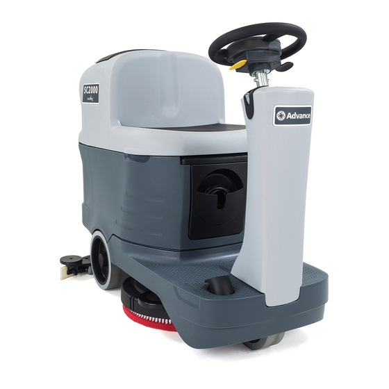
Page 11: Machine Nomenclature (Know Your Machine)
Service Manual – SC2000 General Information Machine Nomenclature (know your machine) EMERGENCY Battery Recovery tank Seat Squeegee hook push-button connector cover Steering wheel with control Dumping recovery panel tank assembly Can holder Solution tank Battery charger cable Solution drain and... - Page 12 Service Manual – SC2000 General Information Machine Nomenclature (Continues) Electronic component EcoFlex™ Tank assembly Batteries compartment detergent tank support rod cover Lifted recovery tank assembly and driver’s seat Recovery water tank cover (open) Vacuum grid with automatic shut-off float Container with debris...
-
Page 13: Control Panel
Service Manual – SC2000 General Information Control Panel Multifunction display and Machine ignition key operating information Operator key (grey) Super user key EcoFlex™ system (yellow) lever Detergent percentage Reverse gear lever adjustment button One-Touch Scrub ON/ Detergent flow OFF push-button... -
Page 14: Service And Diagnostic Equipment
• A copy of the User Manual and Spare Parts List of the machine to be serviced (provided with the machine or available at www.advance-us.com or other Nilfisk-Advance websites). The following equipment is also available at Nilfisk-Advance Centers: • Vacuum water lift gauge, P/N 56205281... -
Page 15: Technical Data
General Information Technical Data Advance / Nilfisk Advance / Nilfisk Description / Model SC2000 53 B SC2000 53 B FULL PKG Solution tank capacity 18.5 US gal (70 liters) Recovery tank capacity 18.5 US gal (70 liters) Machine length 50 in (1,270 mm) Machine width with squeegee 28.3 in (720 mm) -
Page 16: Dimensions
Service Manual – SC2000 General Information Dimensions 28.3 in (720 mm) 50.0 in (1270 mm) Figure 7... -
Page 17: Maintenance
Service Manual – SC2000 General Information Maintenance The lifespan of the machine and its maximum operating safety are ensured by correct and regular maintenance. Warning! Read carefully the instructions in the Safety chapter before performing any maintenance procedure. The following tables provides the scheduled maintenance. The intervals shown may vary according to particular working conditions, which are to be defined by the person in charge of the maintenance. -
Page 18: Frame System
Service Manual – SC2000 Chassis System Chassis System Frame (main parts) Reference to Figure 1 • Steering assembly/column support plate and deck mount • Main support side member • Gearmotor support plate and squeegee system mount Steering assembly/column support plate and deck mount... -
Page 19: Control System
Service Manual – SC2000 Control System Control System Functional Description The architecture of the electronic control system for The display electronic board (EB2) serves mainly the machine’s electrical components is composed of as an aggregator for all input signals (buttons) and... -
Page 20: Component Locations
Service Manual – SC2000 Control System Component Locations • Function electronic board (EB1) • Key electronic board (EB3) • Display electronic board (EB2) • Dashboard instrument electronic board (EB4) Function electronic board (EB1) Figure 2 Dashboard instrument electronic board (EB4) -
Page 21: Maintenance And Adjustments
Service Manual – SC2000 Control System Maintenance and Adjustments Function Electronic Board (EB1) Alarm Codes The function electronic board indicates a series of alarms in case of malfunction of one or more systems, and in case of abnormal conditions detected in the input signals. - Page 22 Service Manual – SC2000 Control System Function Electronic Board (EB1) Alarm Codes (Continues) General alarms Alarm on function electronic board - FLASHING YELLOW + RED LEDS Alarm code -------------------------- Meaning Condition Effect Service Suggestions Flashes Description Blown F2 fuse. Blown F2 fuse.
- Page 23 Service Manual – SC2000 Control System Function Electronic Board (EB1) Alarm Codes (Continues) Function electronic board alarms Alarm on function electronic board - FLASHING RED LED Alarm code flashes on -------------------------- Meaning Condition Effect Service Suggestions electronic Description board BRUSH motor...
- Page 24 Service Manual – SC2000 Control System Function Electronic Board (EB1) Alarm Codes (Continues) Drive system alarms Alarm on function electronic board - FLASHING YELLOW LED Alarm code flashes on -------------------------- Meaning Condition Effect Service Suggestions electronic Description board Amperometric Drive system motor Drive blocked.
- Page 25 Service Manual – SC2000 Control System Function Electronic Board (EB1) Alarm Codes (Continues) On-board Battery Charger Alarms Alarm code -------------------------- Meaning Condition Effect Service Suggestions Description Communication No signal from battery The battery charger Check the wiring between the battery charger...
-
Page 26: Black-Box: Recording Of Alarms, Parameters (See Pages 28-29), Partial Operating Time Counter
Service Manual – SC2000 Control System Black-box: Recording of Alarms, Parameters (see pages 28-29), Partial Operating Time Counter The alarms activated during normal machine operation are stored and can be read in the corresponding log (Alarm Log Screen). Main Screen Insert the super user key (yellow) in place of the operator key (grey) (Figure 6) to access the main screen (Figure 7) of the multifunction display. -
Page 27: Alarm Log Screen
Service Manual – SC2000 Control System Alarm Log Screen The alarms log screen (Figure 8) function allows you to check any alarms stored on the machine. To return to the main screen (Figure 6), press the One-Touch button repeatedly. Figure 8... -
Page 28: Machine Settings Screen
Service Manual – SC2000 Control System Machine Settings Screen The machine settings screen (Figure 9) functions allow you to customise some parameters described in the following table of modifiable parameters. Press the vacuum system button to increase the value of the current parameter. - Page 29 Service Manual – SC2000 Control System Machine Settings Screen (Continues) The following parameters are displayed only when, on reaching the last RESET parameter, the One-Touch button is pressed together with the detergent percentage adjustment button and the detergent flow rate adjustment button If the One-Touch button is not pressed, the system will return to the first parameter CHM1.
-
Page 30: System For Flow Rate Adjustment As Function Of Speed
The default values (the same as in the example above) are summarized in the table, with the corresponding flow rate values in liters per minute, dependent on machine speed, given as a reference. SC2000 detergent flow (as a function of speed) (standard setting) Level 1... -
Page 31: Operating Time Counter Screen
Service Manual – SC2000 Control System Operating Time Counter Screen The operating time counter screen (Figure 10) function allows you to check the total accumulated hours of work for each machine subsystem: • (A) TOTAL counter (machine running time) • (B) DRIVE counter (drive system usage time) •... -
Page 32: Removal And Installation
Service Manual – SC2000 Control System Removal and Installation Function Electronic Board (EB1) Removal/Replacement Drive the machine on a level floor and remove the operator key. Disconnect the red battery connector by pressing the emergency push-button. Lift the recovery tank assembly and the driver’s seat. - Page 33 Service Manual – SC2000 Control System Function Electronic Board (EB1) Removal/Replacement (Continues) Disconnect the following connections sequentially (Figure 13): ◦ (I) Key, accelerator and steering wheel electronic board connection (J1). ◦ (J) Squeegee actuator, beacon light and driver’s seat sensor connection (J3).
-
Page 34: Display Electronic Board (Eb2) And Dashboard Instrument Electronic Board (Eb4) Removal/Replacement
Service Manual – SC2000 Control System Display Electronic Board (EB2) and Dashboard Instrument Electronic Board (EB4) Re- moval/Replacement At the workbench, remove the 6 screws (B), the Display Electronic Board (EB2) cover (C) and recover the gasket (D). Drive the machine on a level floor. - Page 35 Service Manual – SC2000 Control System Display Electronic Board (EB2) and Dashboard Instrument Electronic Board (EB4) Re- moval/Replacement (Continues) Dashboard Instrument Electronic Board (EB4) Assembly Perform points 1 to 5 for removal of the display Assemble the components in the reverse order of electronic board.
-
Page 36: Specifications
Service Manual – SC2000 Control System Specifications Function Electronic Board (EB1) Connectors (Figure 17) Power connections (Ø6mm male RADSOK terminals - AMPHENOL SK 200800532 101 or equivalent) Electronic board Ref. Description V ref. I max. Connected to in/out Electronic board power supply +... - Page 37 Service Manual – SC2000 Control System Function Electronic Board (EB1) Connectors (Continues) (Figure 19) Drive connections (Ø3.6mm male RADSOK terminals - AMPHENOL P/N N01 036 6501 001 or equivalent) Electronic board Ref. Description V ref. I max. Connected to in/out...
- Page 38 Service Manual – SC2000 Control System Function Electronic Board (EB1) Connectors (Continues) (Figure 21) J1: MOLEX MINIFIT type, 12-ways vertical Description Electronic board V ref. I max. Connected to in/out Key electronic board power supply + EB3.1 Return from USER key EB3.2...
- Page 39 Service Manual – SC2000 Control System Function Electronic Board (EB1) Connectors (Continues) (Figure 23) J3: MOLEX MINIFIT type, 6-ways vertical Description Electronic board V ref. I max. Connected to in/out Squeegee actuator power supply +/- 0/24V Driver’s seat microswitch power supply <1A...
- Page 40 Service Manual – SC2000 Control System Function Electronic Board (EB1) Connectors (Continues) (Figure 25) J5: JST VHR-3N type, 3-way vertical Description Electronic board V ref. I max. Connected to in/out Power supply for water level sensor + <1A S1.1 Water level sensor return <1A...
- Page 41 Service Manual – SC2000 Control System Function Electronic Board (EB1) Connectors (Continues) (Figure 27) J7: TYCO MODU II type, 6-ways vertical Description Electronic board V ref. I max. Connected to in/out +24V power supply <1A TRK.RD +5V power supply <1A...
-
Page 42: Display Electronic Board (Eb2) Connectors
Service Manual – SC2000 Control System Display Electronic Board (EB2) Connectors Figure 29 (Figure 29) J1: MOLEX MINIFIT type, 6-ways vertical Electronic Ref. Description V ref. I max. Connected to board in/out Power supply + CFG2.J1.6 Machine startup enabling CFG2.J1.7... -
Page 43: Electrical System
Service Manual – SC2000 Electrical System Electrical System Functional Description The batteries (2 x 12V) are connected together in se- The green cable (terminal 4 of connector C3) is the ries by the cables. data cable between electronic board (EB1) and bat- The battery charger (CH) is connected to the machine tery charger (CH). -
Page 44: Component Locations
Service Manual – SC2000 Electrical System Component Locations • Function electronic board (EB1) • Signal circuit fuse (F2) • Function electronic board fuse (F1) • Battery charger (CH) • Battery connections • Batteries (BAT) • Battery connector (C1) Batteries (BAT) -
Page 45: Maintenance And Adjustments
Service Manual – SC2000 Electrical System Maintenance and Adjustments Setting the Installed Battery Type Set the machine and the on-board battery charger (where fitted) on the basis of the type of battery to be in- stalled by modifying the BAT parameter as shown. Insert the super user key (yellow) in place of the operator key (grey) to access the main screen (Figure 4) of the multifunction display. -
Page 46: Battery Installation
Service Manual – SC2000 Electrical System Battery installation Remove the operator key. Disconnect the battery connector by pressing the emergency push-button. Lift the recovery tank cover and check that it is empty; if not, empty it using the drain hose. - Page 47 Service Manual – SC2000 Electrical System Battery Charging (Continues) Warning! When using lead (WET) batteries, battery charging produces highly explosive hydrogen gas. Charge the batteries in well-ventilated areas and away from naked flames. Do not smoke while charging the batteries. Keep the recovery tank lifted until the battery charging cycle is over.
-
Page 48: Battery Charge State Display
Service Manual – SC2000 Electrical System Battery Charge State Display (Significant levels for machine operation) TRANSITION THRESHOLD (VOLT) INDICATION CONSEQUENCE 22.2V Little remaining run time, no block. 20.4V 21.6V Brush OFF 19.4V 20.6V Vacuum system OFF 18.4V 19.6V Drive system OFF Checking/Replacing Fuses Drive the machine on a level floor and remove the operator key. -
Page 49: Troubleshooting
Service Manual – SC2000 Electrical System Troubleshooting See the other chapters for previously provided instructions for other electrical system components. Trouble Possible Causes Remedy The machine is not working Batteries (BAT) flat or connections faulty Charge the battery or clean the... -
Page 50: General Wiring Diagram
Service Manual – SC2000 Electrical System General Wiring Diagram FUNCTION ELECTRONIC BOARD (EB1) USB PORT 5V POWER UNIT (EB5) BATTERY CONNECTOR (C1) (USB) Electronic board power supply + J8.4 Opt power supply - BRUSH Brush motor + MOTOR (M1) J8.9... -
Page 51: Specifications
Specifications Advance / Nilfisk Advance / Nilfisk Description / Model SC2000 53 B SC2000 53 B FULL PKG Battery compartment size (length x width x height) 13.7x14.1x11 in (350x360x280 mm) Standard batteries (2) Discover 12V-105Ah Standard battery run time (capacity) 2.5 h... -
Page 52: Recovery Water System
Service Manual – SC2000 Recovery System Recovery System Functional Description The recovery system removes the dirty water from The vacuum duct for connecting the vacuum grid to the floor and pipes it to a recovery tank. When the the vacuum system motor (M2) is inside the recovery machine is running, the dirty water on the floor is col- tank cover. -
Page 53: Component Locations
Service Manual – SC2000 Recovery System Component Locations • Recovery tank • Squeegee vacuum hose • Recovery tank cover • Vacuum system motor (M2) • Cover gasket • Container with debris collection grid • Vacuum system motor filter • Vacuum grid with automatic shut-off float •... -
Page 54: Maintenance And Adjustments
Service Manual – SC2000 Recovery System Maintenance and Adjustments Recovery Tank Cleaning Drive the machine to the appointed disposal Note: The gasket (E) creates the area. vacuum in the tank that is necessary to vacuum up the Drain the water from the tank using the drain recovery water. -
Page 55: Troubleshooting
Service Manual – SC2000 Recovery System Troubleshooting Trouble Possible Causes Remedy The vacuum system motor will not turn Wiring between function electronic board (EB1) and Repair vacuum system motor (M2) damaged Dashboard instrument electronic board (EB4) faulty Replace Vacuum system motor faulty... -
Page 56: Removal And Installation
Service Manual – SC2000 Recovery System Removal and Installation Vacuum System Motor Amperage Test Warning! This procedure must be performed by qualified personnel only. 12. Lift the recovery tank assembly and the driver’s seat. 13. Apply the amp clamp (A) to a cable (B) near the vacuum unit (Figure 5). -
Page 57: Vacuum System Motor Unit Disassembly/Assembly
Service Manual – SC2000 Recovery System Vacuum System Motor Unit Disassembly/Assembly Disassembly Remove the operator key. Disconnect the red battery connector. If present, drain the recovery tank, then lift it. Disconnect the connector (A) (Figure 6) and remove the fastening clamp. -
Page 58: Container And Vacuum System Motor Disassembly/Assembly
Service Manual – SC2000 Recovery System Container and Vacuum System Motor Disassembly/Assembly Disassembly Disassemble the vacuum system motor unit as shown in the previous paragraph. At the workbench, remove the connector (A) (Figure 7) form the faston terminals (B). Remove the clamp (C). - Page 59 Service Manual – SC2000 Recovery System Container and Vacuum System Motor Disassembly/Assembly (Continues) Clean the inside of the containers from any dirt that has settled and check all gaskets (J) (Figure 9) for wear; replace if necessary. Figure 9 Assembly Check that all components are reassembled with the correct polarity and orientation.
-
Page 60: Specifications
Recovery System Specifications Advance / Nilfisk Advance / Nilfisk Description / Model SC2000 53 B SC2000 53 B FULL PKG Recovery tank capacity 18.5 US gal (70 liters) Power 0.4 hp (310 W) Vacuum system motor technical data Insulation Class... -
Page 61: Scrub System, Disc
Service Manual – SC2000 Scrub System, Disc Scrub System, Disc Functional Description The disc brush system can be started by the operator. The overload is detected by monitoring the current The disc brush turn counter-clockwise. flow sum on the brush motor. The current is mea-... -
Page 62: Brush Deck Actuator System
Scrub System, Disc Brush Deck Actuator System The brush deck actuator of SC2000 is a new generation actuator developed by SIR and ITALSEA and it is controlled directly by the main board without electromechanical limit switches. ITALSEA patented the system to control the actuator. -
Page 63: Component Locations
Service Manual – SC2000 Scrub System, Disc Component Locations • Brush motor (M1) • Brush deck support • Disc brush deck • Drive hub • Deck raising levers Brush motor (M1) Deck raising levers Disc brush deck Brush deck support... - Page 64 Service Manual – SC2000 Scrub System, Disc Component Locations (Continues) • Brush deck lifting/lowering actuator (M5) • Function electronic board (EB1) • Actuator system wiring connection Brush deck lifting/ lowering actuator (M5) Figure 4 Actuator system wiring connection Function electronic...
-
Page 65: Brush Installation/Removal
Service Manual – SC2000 Scrub System, Disc Maintenance and Adjustments Brush Installation/Removal According to the kind of cleaning to be To remove the brush, the deck must be lifted performed, the machine can be equipped either with the brush (A) (Figure 5) or the pad-holder... -
Page 66: Troubleshooting
Service Manual – SC2000 Scrub System, Disc Troubleshooting Trouble Possible Causes Remedy The brush does not clean properly The brush is excessively worn Replace One brush does not turn See the chapter Control System, Function Electronic Board (EB1) Error Codes... -
Page 67: Removal And Installation
Service Manual – SC2000 Scrub System, Disc Removal and Installation Brush Motor Amperage Check Note: Use a jumper wire to disable Warning! This procedure must be the driver’s seat sensor. performed by qualified personnel only. Activate the brush by pressing the accelerator Drive the machine on a level floor. -
Page 68: Brush Deck Disassembly/Assembly
Service Manual – SC2000 Scrub System, Disc Brush Deck Disassembly/Assembly Disassembly Drive the machine on a level floor or on a hoisting system to facilitate the disassembly procedures. Remove the brush. Place two wooden shims (B, Figure 7), at least 4 cm thick, under the brush deck (A). - Page 69 Service Manual – SC2000 Scrub System, Disc Brush Deck Disassembly/Assembly (Continues) Warning! To easly remove the brush deck, lift the machine body at the front side as shown (L, Figure 9). Use extreme caution and follow the safety regulations using proper equipment or safety fixed supports suitable for the purpose.
-
Page 70: Checking/Replacing Brush Motor Carbon Brushes
Service Manual – SC2000 Scrub System, Disc Checking/Replacing Brush Motor Carbon Brushes Check Remove the brush deck. Remove any dust and dirt from around the brush motor carbon brushes. Remove the four protective covers (A) (Figure 10) by disconnecting the clips. -
Page 71: Brush Motor Disassembly/Assembly
Service Manual – SC2000 Scrub System, Disc Brush Motor Disassembly/Assembly Disassembly Assembly Remove the brush deck. Assemble the components in the reverse order of At the workbench, remove the screw (A) (Figure disassembly. 11) of the brush motor. Use a puller to remove the brush hub (B). -
Page 72: Brush Deck Actuator Disassembly/Assembly
Service Manual – SC2000 Scrub System, Disc Brush Deck Actuator Disassembly/Assembly Disassembly Drive the machine on a level floor. Lift the recovery tank assembly and the driver’s seat. Place two wooden shims (B, Figure 12), at least 4 cm thick, under the brush deck (A). -
Page 73: Specifications
Specifications Advance / Nilfisk Advance / Nilfisk Description / Model SC2000 53 B SC2000 53 B FULL PKG Cleaning width 21 in (530 mm) Brush/pad diameter 21 in (530 / 508 mm) Brush pressure with extra pressure function turned off... -
Page 74: Solution System
Service Manual – SC2000 Solution System Solution System Functional Description The solution system supplies water and detergent to ter Control System). the brush when cleaning the floor. The solution tank is Located centrally, below the solution tank, there is also the main machine body. There is a manual valve... -
Page 75: Component Locations
Service Manual – SC2000 Solution System Component Locations • Solution tank • Solution drain and level check hose • Solution tank filler plug • Solution valve • Water removable filler hose • Solution filter • Solenoid valve (EV1) Solution tank filler plug... - Page 76 Service Manual – SC2000 Solution System Component Locations (Continues) • EcoFlex™ detergent tank • Water level sensor (S1) • Plug with detergent supply hose • Battery compartment liquid drain hole • EcoFlex™ detergent pump (M4) Water level sensor (S1) EcoFlex™ detergent tank EcoFlex™...
-
Page 77: Maintenance And Adjustments
Service Manual – SC2000 Solution System Maintenance and Adjustments Cleaning the Solution Tank and Filter Drive the machine on a level floor. Remove the transparent cover (A, Figure 5), retrieve the gasket (B), then remove the filter Ensure that the machine is off and the operator strainer (C). -
Page 78: Cleaning The Ecoflex™ Detergent Tank
Service Manual – SC2000 Solution System Cleaning the EcoFlex™ Detergent Tank Drive the machine to the appointed disposal Remove the tank. area. Rinse and wash out the tank with clean water in Ensure that the machine is off and the operator the appointed disposal area. -
Page 79: Draining The Ecoflex™ System
Service Manual – SC2000 Solution System Draining the EcoFlex™ System Clean the detergent tank as shown in the previous section. To remove residual detergent from the detergent hoses and pump, proceed as follows. Clean the detergent tank as shown in the previous section. -
Page 80: Troubleshooting
Service Manual – SC2000 Solution System Troubleshooting Trouble Possible Causes Remedy Small amount of solution or no solution The solution filter is clogged/dirty Clean the filter reaches the brush Solution supply valve locked in (semi) closed position Replace the valve... - Page 81 Service Manual – SC2000 Solution System Troubleshooting (Continues) Trouble Possible Causes Remedy The EcoFlex™ system detergent is not The detergent flow percentage is too low Check/change the percentage as reaching the brush, or is not arriving in shown in the User Manual...
-
Page 82: Removal And Installation
Service Manual – SC2000 Solution System Removal and Installation Solenoid Valve Disassembly/Assembly Switch off the machine and disconnect the Disassembly battery connector. Drive the machine on a level floor or on a hoisting system to facilitate the disassembly Unscrew and disconnect the connection (B). -
Page 83: Detergent Pump Disassembly/Assembly
Service Manual – SC2000 Solution System Detergent Pump Disassembly/Assembly Disassembly Drive the machine on a level floor. Switch off the machine and disconnect the battery connector. Lift the recovery tank assembly and the driver’s seat, then disassemble the electronic component compartment cover. -
Page 84: Checking The Water Level Sensor Operation
Service Manual – SC2000 Solution System Checking the Water Level Sensor Operation Insert the super user key (yellow) in place of the operator (grey) key to access the main screen (Figure 10) of the multifunction display. With the solution tank more than half full, the symbol displayed is (A). -
Page 85: Water Level Sensor Disassembly/Assembly
Service Manual – SC2000 Solution System Water Level Sensor Disassembly/Assembly Drive the machine on a level floor. Switch off the machine and disconnect the battery connector. Lift the recovery tank assembly and the driver’s seat, then disassemble the electronic component compartment cover. -
Page 86: Specifications
Advance / Nilfisk Advance / Nilfisk Description / Model SC2000 53 B SC2000 53 B FULL PKG Solution tank capacity 18.5 US gal (70 liters) Solution flow values 0.75 cl/m / 1.5 cl/m / 3.0 cl/m / (2.8 L/min, if enabled) EcoFlex™... -
Page 87: Squeegee System
Service Manual – SC2000 Squeegee System Squeegee System Functional Description The squeegee system cleans the liquid off the floor, which is then collected by the recovery system. The squeegee is mounted on castors and the weight of the system presses it down on the floor. -
Page 88: Component Locations
Service Manual – SC2000 Squeegee System Component Locations • Bumper wheels • Squeegee blades • Squeegee reset spring • Squeegee adjusting knob • Squeegee support • Mounting handwheels • Actuator (M6) • Tie rods Actuator (M6) Squeegee reset spring Squeegee support... -
Page 89: Maintenance And Adjustments
Service Manual – SC2000 Squeegee System Maintenance and Adjustments Squeegee cleaning Loosen the handwheels and remove the Note: The squeegee must be clean squeegee. and its blades must be in good conditions in order to get a good Wash and clean the squeegee. In particular, drying. -
Page 90: Checking/Replacing The Squeegee Blades
Service Manual – SC2000 Squeegee System Checking/Replacing the Squeegee Blades Note: The squeegee must be clean and its blades must be in good conditions in order to get a good drying. Warning! It is advisable to wear protective gloves when cleaning the squeegee because there may be sharp debris. -
Page 91: Troubleshooting
Service Manual – SC2000 Squeegee System Troubleshooting Trouble Possible Causes Remedy Suction of dirty water is insufficient or Squeegee or vacuum hose clogged or damaged Clean or repair/replace non-existent The squeegee leaves lining on the floor There is debris under the blade... -
Page 92: Removal And Installation
Service Manual – SC2000 Squeegee System Removal and Installation Squeegee Lifting Actuator Disassembly/Assembly Disassembly Drive the machine on a level floor. Lower the squeegee. Ensure that the machine is off and the operator key has been removed. Disassemble the retaining spring (A, Figure 4), retrieve screws and washers. -
Page 93: Squeegee Tie Rod Disassembly/Assembly
Service Manual – SC2000 Squeegee System Squeegee Tie Rod Disassembly/Assembly Disassembly Drive the machine on a level floor or on a hoisting system to facilitate the disassembly procedures. Lower the squeegee. Ensure that the machine is off and the operator key has been removed. -
Page 94: Specifications
Service Manual – SC2000 Squeegee System Specifications Advance / Nilfisk Advance / Nilfisk Description / Model SC2000 53 B SC2000 53 B FULL PKG Squeegee width 28.3 in (720 mm) Spring load 70 ÷ 100 N Total travel 3 in (77 mm) -
Page 95: Steering System
Service Manual – SC2000 Steering System Steering System Functional Description The steering system connects the steering wheel to the front wheel. The reduction gear pinion transmits the movement to the steering crown connected to the front wheel. The front wheel assembly is equipped with anti-skid control sensor (SW4). -
Page 96: Specifications
Specifications Advance / Nilfisk Advance / Nilfisk Description / Model SC2000 53 B SC2000 53 B FULL PKG Turning space for U-turns 71 in (1800 mm) Front steering wheel diameter 7.9 in (200 mm) Front wheel specific pressure on the floor (*) 189 psi (1.3 N/mm... -
Page 97: Wheels, Drive System
Service Manual – SC2000 Wheels, Drive System Wheels, Drive System Functional Description Machine movement is provided by the gearmotor unit The electromagnetic brake keeps the machine braked (M3). when the machine is off or whenever it is stopped. The gearmotor unit (M3) consists of an electrical mo-... -
Page 98: Wiring Diagram
Service Manual – SC2000 Wheels, Drive System Wiring Diagram FUNCTION ELECTRONIC DRIVE PEDAL Electronic board power supply + BOARD (EB1) POTENTIOMETER (RV1) DRIVE SYSTEM Drive system motor + MOTOR (M3) J1.1 J1.10 Pedal power supply + J1.2 J1.11 Return from pedal Drive system motor - J1.3... -
Page 99: Component Locations
Service Manual – SC2000 Wheels, Drive System Component Locations • Drive pedal with potentiometer (RV1) • Electromagnetic brake (BRK) • Driving wheels • Driver’s seat microswitch (SW3) • Gearmotor unit (M3) Driver’s seat Drive pedal with microswitch (SW3) potentiometer (RV1) -
Page 100: Troubleshooting
Service Manual – SC2000 Wheels, Drive System Troubleshooting Trouble Possible Causes Remedy The machine does not move Battery voltage too low Charge the battery Speed potentiometer (RV1) incorrectly regulated or Replace broken Function electronic board (EB1) faulty Replace Wiring damaged... -
Page 101: Removal And Installation
Service Manual – SC2000 Wheels, Drive System Removal and Installation Drive Pedal Potentiometer Disassembly/Assembly Disassembly Drive the machine on a level floor or on a hoisting system to facilitate the disassembly procedures. Remove the operator key and disconnect the red battery connector Lift the machine as shown (A, Figure 4). -
Page 102: Drive System Gearmotor Amperage Test
Service Manual – SC2000 Wheels, Drive System Drive System Gearmotor Amperage Test Warning! This procedure must be performed by qualified personnel only and with the help of an assistant. Drive the machine on a level floor. Lift the recovery tank assembly and the driver’s seat. Apply a jumper wire (A, Figure 5) on the driver’s seat sensor connector to disable the system. -
Page 103: Drive System Gearmotor Disassembly/Assembly
Service Manual – SC2000 Wheels, Drive System Drive System Gearmotor Disassembly/Assembly Warning! This procedure must be performed by qualified personnel only and with the help of an assistant. Drive the machine on a level floor or on a hoisting system to facilitate the disassembly procedures. Place a suitable lifting device (A, Figure 5) to raise one side of the machine approximately 2 cm from the floor. -
Page 104: Gearmotor Carbon Brushes Check/Replacement
Service Manual – SC2000 Wheels, Drive System Gearmotor Carbon Brushes Check/Replacement Check Remove the gearmotor unit from the machine. At the workbench, remove any dust and dirt from around the drive system motor carbon brushes. Remove the clamp (A, Figure 6) by disengaging the tab (B). -
Page 105: Drive System Motor Electromagnetic Brake Disassembly/Assembly
Service Manual – SC2000 Wheels, Drive System Drive System Motor Electromagnetic Brake Disassembly/Assembly Disassembly Remove the gearmotor unit from the machine. At the workbench, remove dust and debris around the electromagnetic brake. Remove the two screws (A, Figure 7) and the electromagnetic brake (B). -
Page 106: Drive System Motor Disassembly/Assembly
Service Manual – SC2000 Wheels, Drive System Drive System Motor Disassembly/Assembly Disassembly Remove the gearmotor unit from the machine. At the workbench, remove dust and debris from the drive system motor. Remove the clamp (A, Figure 8) by disengaging the tab (B). -
Page 107: Specifications
Specifications Advance / Nilfisk Advance / Nilfisk Description / Model SC2000 53 B SC2000 53 B FULL PKG Rear driving wheel diameter 10 in (254 mm) Rear driving wheel specific pressure on the floor (*) 145 psi (1.0 N/mm Power 0.53 hp (400 W)
Need help?
Do you have a question about the SC2000 and is the answer not in the manual?
Questions and answers
I need a technician to come out and look at our Advance DC 2000 Ecoflex machine. We are located in Willis Texas 77318