Nilfisk-Advance SC450 Service Manual
Hide thumbs
Also See for SC450:
- Instructions for use manual (100 pages) ,
- User manual (76 pages) ,
- How-to manual (3 pages)

Related Manuals for Nilfisk-Advance SC450


Summary of Contents for Nilfisk-Advance SC450
-
Page 1: Service Manual
SC450 Service Manual Advance SC450, 9087331020 Nilfisk SC450, 9087330020 - 9087370020 Nilfisk SC450, 9087332020 - 9087372020 English 11-12 - Revised 4-14 (2) Form No. 9099600000... -
Page 2: Table Of Contents
Service Manual – SC450 Index Index Index General Information Machine General Description Service Manual Purpose and Field of Application Other Reference Manuals Conventions Service and Spare Parts Serial Number Label Safety Symbols General Instructions Machine Lifting Machine Transportation Machine Nomenclature Battery Version (know your machine) - Page 3 Service Manual – SC450 Index Recovery System - Battery Version Functional Description Wiring Diagram Component Location Maintenance and Adjustments Troubleshooting Removal and Installation Specifications Recovery System - Cable Version Functional Description Wiring Diagram Component Location Maintenance and Adjustments Troubleshooting Removal and Installation...
- Page 4 Service Manual – SC450 Index Squeegee System Functional Description Component Location Maintenance and Adjustments Troubleshooting Removal and Installation Specifications Wheel System, Non-Traction Component Location Specifications...
-
Page 5: General Information
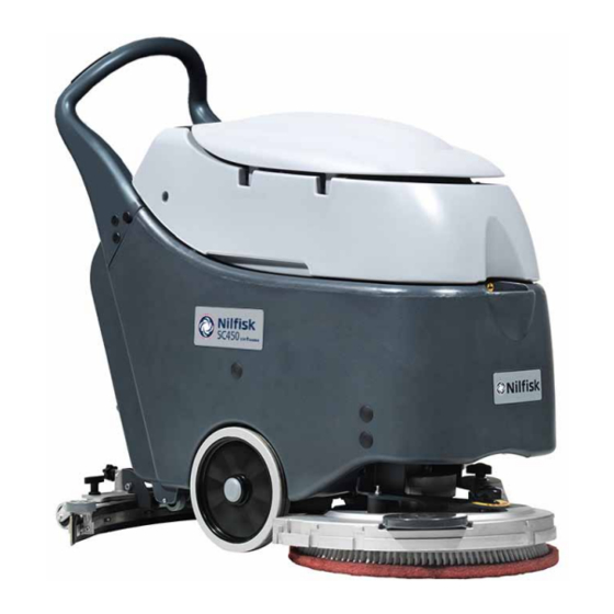
General Information Machine General Description The SC450 is a “walk behind” industrial machine designed to wash and dry floors, in civil or industrial envi- ronments, in one pass. The machine is powered by on-board batteries (Battery version) and with electric mains via power supply cable (cable version). -
Page 6: Conventions
This information is useful when requiring machine spare parts Use the following table to write down the machine identification data. Serial No: ....Model: Scrubber-Dryer SC450 20 B Date code: ..Prod. Nr: 9087331020 IPX4 GVW: 190 kg/419 lb LpA = 68 dB(A) -
Page 7: Safety
Service Manual – SC450 General Information Safety The following symbols indicate potentially dangerous situations Always read this information carefully and take all necessary precautions to safeguard people and property Symbols Danger! It indicates a dangerous situation with risk of death for the operator. - Page 8 Service Manual – SC450 General Information Caution! Make sure to follow the safety precautions to avoid situations that may lead to serious injuries, damages to materials or equipments. – Carefully read all the instructions before performing any maintenance/repair procedure. – Always protect the machine against the sun, rain and bad weather, both under operation and inactivity condition.
- Page 9 Service Manual – SC450 General Information – BATTERY Version - Before using the battery charger, ensure that frequency and voltage val- ues, indicated on the machine serial number plate, match the mains voltage. – Do not pull or carry the machine by the battery charger cable and never use the battery charger cable as a handle.
-
Page 10: Machine Lifting
Service Manual – SC450 General Information Machine Lifting Warning! Do not work under the lifted machine, if it is not securely fixed. Machine Transportation Warning! Before transporting the machine, make sure that: All covers are closed. The solution and recovery tanks are emptied. The batteries are disconnected. The machine is securely fastened to the means of transport. -
Page 11: Machine Nomenclature Battery Version (Know Your Machine)
Service Manual – SC450 General Information Machine Nomenclature Battery Version (know your machine) Control panel Battery charger data inspection window Can holder Handlebar Recovery tank cover Battery charger cable Battery charger cable holder Recovery tank Squeegee lifting/lowering lever Solution tank... - Page 12 Service Manual – SC450 General Information Machine Nomenclature Battery Version (Continues) Recovery tank cover Tank (completely opened) cover gasket Recovery tank cover (half-open) Vacuum grid with automatic shut-off float Water removable filler hose Battery connectio diagram Battery Solution caps filler neck...
-
Page 13: Control Panel Battery Version
Service Manual – SC450 General Information Control Panel Battery Version Green LED - charged battery Brush switch Vacuum system switch Yellow LED - semi-discharged battery Red LED - discharged battery Brush enabling Brush enabling Brush enabling Brush enabling push-button push-button... -
Page 14: Machine Nomenclature Cable Version (Know Your Machine)
Service Manual – SC450 General Information Machine Nomenclature Cable Version (know your machine) Control panel Handlebar Can holder Recovery tank cover Power supply cable holder Power supply cable Recovery tank Squeegee Solution lifting/lowering lever tank Serial number plate/technical Solution drain... - Page 15 Service Manual – SC450 General Information Machine Nomenclature Cable Version (Continues) Recovery tank cover Tank (completely opened) cover gasket Recovery tank cover (half-open) Vacuum grid with automatic shut-off float Water removable filler hose Recovery tank mounting Solution screws (do not remove!)
-
Page 16: Control Panel Cable Version
Service Manual – SC450 General Information Control Panel Cable Version Interruttore spazzola Interruttore impianto di aspirazione Pulsante di azionamento Pulsante di azionamento Pulsante di azionamento Pulsante di azionamento spazzola spazzola spazzola spazzola P200004E... -
Page 17: Service And Diagnostic Equipment
• Dynamometric wrench set • A copy of the Instruction for use and Spare Parts List of the machine to be serviced (provided with the machine or available at www.advance-us.com or other Nilfisk-Advance websites). The following equipment is also available at Nilfisk-Advance Centers:... -
Page 18: Technical Data Battery Version
Service Manual – SC450 General Information Technical Data Battery Version Advance Nilfisk Descriptions / Model SC450 20B SC450 53B Solution tank capacity 10.5 US gal (40 liters) Recovery tank capacity 11.9 US gal (45 liters) Machine length 46.4 in (1,180 mm) -
Page 19: Technical Data Cable Version
Service Manual – SC450 General Information Technical Data Cable Version Nilfisk Descriptions / Model SC450 53E Solution tank capacity 10.5 US gal (40 liters) Recovery tank capacity 11.9 US gal (45 liters) Machine length 46.4 in (1,180 mm) Machine width without squeegee... -
Page 20: Dimensions
Service Manual – SC450 General Information Dimensions 46.4 in (1,180 mm) 30 in (760 mm) P200005... -
Page 21: Maintenance
Service Manual – SC450 General Information Maintenance The lifespan of the machine and its maximum operating safety are ensured by correct and regular mainte- nance Warning! Read carefully the instructions in the Safety chapter before performing any maintenance procedure. The following table provides the scheduled maintenance The intervals shown may vary according to particu- lar working conditions, which are to be defined by the person in charge of the maintenance. -
Page 22: Control System - Battery Version
Service Manual – SC450 Control System - Battery Version Control System - Battery Version Functional Description The function control is performed directly by the brush switch (SW1), the vacuum system switch (SW2) and the brush activation push-buttons (SW3 with SW4) -
Page 23: Component Location
Service Manual – SC450 Control System - Battery Version Component Location • Brush switch (SW1) • Vacuum system switch (SW2) • Brush activation push-button (SW3) • Battery voltage LEDs • Function electronic board (EB1) • LED electronic board (EB2) • Wiring harness... -
Page 24: Removal And Installation
Service Manual – SC450 Control System - Battery Version Removal and Installation Function Electronic Board Disassembly/Assembly Disassembly Drive the machine on a level floor. Make sure that the machine cannot move independently. Check that the control panel switches are turned to “0” Disconnect the battery connector (red) Move aside the recovery water drain hose Remove the battery charger cable, if equipped, from the cable holder. - Page 25 Service Manual – SC450 Control System - Battery Version Brush Activation Push-Button Disassembly/Assembly (old version) Disassembly Drive the machine on a level floor. Make sure that the machine cannot move independently. Check that the control panel switches are turned to “0” Disconnect the battery connector (red)
- Page 26 Service Manual – SC450 Control System - Battery Version Brush Activation Push-Button Disassembly/Assembly (new version) Smontaggio Drive the machine on a level floor. Make sure that the machine cannot move independently. Check that the control panel switches are turned to “0” Disconnect the battery connector (red)
-
Page 27: Specifications
Service Manual – SC450 Control System - Battery Version Specifications Function Electronic Board Specifications The function electronic board performs the following: a BRUSH MOTOR PROTECTION: By reading the voltage drop across (F1) fuse, the main brush motor amperage (M1) is monitored. If the voltage drop is higher than 40 mV, the 3 LEDs on the LED electronic board (EB2) start flashing simultaneously. -
Page 28: Connectors On The Function Electronic Board
Service Manual – SC450 Control System - Battery Version Connectors on the Function Electronic Board P200010 J1 - 8 WAY-CONNECTOR Description Voltage Ref. to B - Switch power supply Brush switch activation Vacuum system switch Red LED (<=> EB2 PIN 2) Yellow LED (<=>... -
Page 29: Control System - Cable Version
Service Manual – SC450 Control System - Cable Version Control System - Cable Version Functional Description The function control is performed directly by the brush switch (SW1), the vacuum system switch (SW2) and the brush activation push-buttons (SW3 with SW4) -
Page 30: Component Location
Service Manual – SC450 Control System - Cable Version Component Location • Brush switch (SW1) • Vacuum system switch (SW2) • Brush activation push-buttons (SW3) (SW4) • Mains filter (FL1) • Brush motor relay (ES1) Brush switch (SW1) Vacuum system switch (SW2) -
Page 31: Removal And Installation
Service Manual – SC450 Control System - Cable Version Removal and Installation Brush Activation Push-Button Disassembly/Assembly (old version) Disassembly Drive the machine on a level floor. Make sure that the machine cannot move independently. Make sure that the power supply cable plug is disconnected from the electrical mains... - Page 32 Service Manual – SC450 Control System - Cable Version Brush Activation Push-Button Disassembly/Assembly (new version) Smontaggio Drive the machine on a level floor. Make sure that the machine cannot move independently. Make sure that the power supply cable plug is disconnected from the electrical mains...
-
Page 33: Electrical System - Battery Version
Service Manual – SC450 Electrical System - Battery Version Electrical System - Battery Version Functional Description Basically the electrical system consists of a function tor (C2) is disconnected from the electrical mains electronic board (EB1) which determines the brush When the battery charger is connected to the electri-... -
Page 34: Component Location
Service Manual – SC450 Electrical System - Battery Version Component Location • Batteries (BAT) • Electrical component box • Battery connections • Brush fuse (F1) • Battery charger (CH) • Vacuum fuse (F2) • Battery connector (C1) • Control/solenoid fuse (F3) -
Page 35: Maintenance And Adjustments
Service Manual – SC450 Electrical System - Battery Version Maintenance and Adjustments Battery Installation And Battery Type Setting (WET or GEL/AGM) Set the electronic board of the machine and of the battery charger (if equipped) according to the type of batter-... - Page 36 Service Manual – SC450 Electrical System - Battery Version Battery Installation And Battery Type Setting (WET or GEL/AGM) (Continues) Battery Charger Setting (for machines with on-board battery charger) Remove the battery charger data inspection window screws (N) Remove the window (H) Turn the battery charger selector (I) to WET for lead batteries, or to GEL for GEL/AGM batteries.
-
Page 37: Battery Charging
Service Manual – SC450 Electrical System - Battery Version Battery Charging Note: Charge the batteries when the yellow or red warning light on the control panel turns on, or at the end of every working cycle. Caution! Keeping the batteries charged make their life last longer. - Page 38 Service Manual – SC450 Electrical System - Battery Version Battery Charging (Continues) Charging the Batteries with an External Battery Charger Check that the external battery charger is suitable by referring to the battery charger Manual The battery charger voltage rating must be 24 V...
- Page 39 Service Manual – SC450 Electrical System - Battery Version Battery Charging (Continues) Charging the Batteries with an (Optional) Battery Charger Installed on the Machine Connect the battery charger cable (D) to the electrical mains (the electrical mains voltage and frequency must be compatible with the battery charger values shown on the machine serial number...
- Page 40 Service Manual – SC450 Electrical System - Battery Version Fuse Check and Replacement Drive the machine on a level floor. Make sure that the machine cannot move independently. Check that the control panel switches are turned to “0” Disconnect the battery connector (red) Move aside the recovery water drain hose Remove the battery charger cable, if equipped, from the cable holder.
-
Page 41: Troubleshooting
Service Manual – SC450 Electrical System - Battery Version Charge condition display TRANSITION THRESHOLD (VOLT) INDICATION CONSEQUENCE GREEN LED: fixed - YELLOW LED: fixed 22 V 22.2 V Brushes + Vacuum system YELLOW LED: fixed - RED LED: flashing 20.4 V 21.6 V... -
Page 42: Machine Wiring Diagram
Service Manual – SC450 Electrical System - Battery Version Machine Wiring Diagram CONNECTOR + (C1) VACUUM SYSTEM MOTOR FUSE (F2) CONNECTOR (C2) ELECTRONIC BOARD LED (EB2) VACUUM SYSTEM BRUSH FUNCTION ELECTRONIC SWITCH (SW2) SWITCH (SW1) BOARD (EB1) BRUSH MOTOR (M1) -
Page 43: Specifications
Service Manual – SC450 Electrical System - Battery Version Specifications Advance Nilfisk Descriptions / Model SC450 20B SC450 53B Total absorbed power 34 A (0.8 kW) Battery compartment size (width x length x height) 350 x 350 x 300 mm (13.7 x 13.7 x 11.8 in) -
Page 44: Electrical System - Cable Version
Service Manual – SC450 Electrical System - Cable Version Electrical System - Cable Version Wiring Diagram MAINS PLUG (PL) MAINS FILTER (FL1) BRUSH SWITCH (SW1) VACUUM SWITCH (SW2) BRUSH ACTIVATION HEART SCREW (HS) PUSH-BUTTONS (SW3) (SW4) BRUSH MOTOR RELAY (ES1) -
Page 45: Specifications
Service Manual – SC450 Electrical System - Cable Version Specifications Nilfisk Descriptions / Model SC450 53E Total absorbed power 7.5 A (1.7 kW) Power supply 230 V - 50-60 Hz... -
Page 46: Recovery System - Battery Version
Service Manual – SC450 Recovery System - Battery Version Recovery System - Battery Version Functional Description The water recovery system removes the dirty water The automatic float in the vacuum grid stops vacuum from the floor and pipes it to a recovery tank. When... -
Page 47: Component Location
Service Manual – SC450 Recovery System - Battery Version Component Location • Recovery tank • Vacuum system motor (M2) • Vacuum grid with automatic shut-off float • Electrical component box • Recovery tank cover • Vacuum fuse (F2) • Cover gasket •... -
Page 48: Maintenance And Adjustments
Service Manual – SC450 Recovery System - Battery Version Maintenance and Adjustments Tank and Vacuum Grid Cleaning Drive the machine to the appointed disposal area Check that the control panel switches are turned to “0” Disconnect the battery connector (red) -
Page 49: Troubleshooting
Service Manual – SC450 Recovery System - Battery Version Troubleshooting Trouble Possible Causes Remedy The vacuum system motor does not turn The vacuum system motor carbon brushes are worn Replace The switch (SW2) is broken Replace The vacuum system motor is faulty Check the amperage. -
Page 50: Removal And Installation
Service Manual – SC450 Recovery System - Battery Version Removal and Installation Vacuum System Motor Amperage Check Warning! This procedure must be performed by qualified personnel only. Check that the squeegee and the vacuum hose are clean and that there is no dirt in their inner parts Keep the squeegee lifted... - Page 51 Service Manual – SC450 Recovery System - Battery Version Vacuum System Motor Carbon Brush Check/Replacement Disassembly/Check Remove the vacuum system motor (see the procedure in the Vacuum System Motor Disassembly/ Assembly paragraph) At the workbench, remove the sealing ring (A) from the vacuum system motor (B).
- Page 52 Service Manual – SC450 Recovery System - Battery Version Vacuum System Motor Disassembly/Assembly Remove the recovery water tank Loosen the fastener (A) and disconnect the hose (B) from the vacuum system motor below Remove the screws (C) and remove the cover (D)
-
Page 53: Specifications
Service Manual – SC450 Recovery System - Battery Version Specifications Advance Nilfisk Descriptions / Model SC450 20B SC450 53B Recovery tank capacity 11.9 US gal (45 liters) Vacuum power 0.44 hp (330 W) Vacuum water lift (blocked) 43.3 inH O (1,100 mmH... -
Page 54: Recovery System - Cable Version
Service Manual – SC450 Recovery System - Cable Version Recovery System - Cable Version Functional Description The water recovery system removes the dirty water The automatic float in the vacuum grid stops vacuum from the floor and pipes it to a recovery tank. When... -
Page 55: Component Location
Service Manual – SC450 Recovery System - Cable Version Component Location • Recovery tank • Recovery water drain hose • Vacuum grid with automatic shut-off float • Recovery water vacuum hose • Recovery tank cover • Vacuum system motor (M2) •... -
Page 56: Maintenance And Adjustments
Service Manual – SC450 Recovery System - Cable Version Maintenance and Adjustments Tank and Vacuum Grid Cleaning Drive the machine to the appointed disposal area Check that the control panel switches are turned to “0” Disconnect the battery connector (red) -
Page 57: Troubleshooting
Service Manual – SC450 Recovery System - Cable Version Troubleshooting Trouble Possible Causes Remedy The vacuum system motor does not turn The vacuum system motor carbon brushes are worn Replace The switch (SW2) is broken Replace The vacuum system motor is faulty Check the amperage. -
Page 58: Removal And Installation
Service Manual – SC450 Recovery System - Cable Version Removal and Installation Vacuum System Motor Amperage Check Warning! This procedure must be performed by qualified personnel only. Check that the squeegee and the vacuum hose are clean and that there is no dirt in their inner parts Keep the squeegee lifted... - Page 59 Service Manual – SC450 Recovery System - Cable Version Vacuum System Motor Carbon Brush Check/Replacement Disassembly/Check Remove the vacuum system motor (see the procedure in the Vacuum System Motor Disassembly/ Assembly paragraph) At the workbench, remove the sealing ring (A) from the vacuum system motor (B).
- Page 60 Service Manual – SC450 Recovery System - Cable Version Vacuum System Motor Disassembly/Assembly Remove the recovery water tank Loosen the fastener (A) and disconnect the hose (B) from the vacuum system motor below Remove the screws (C) and remove the cover (D)
-
Page 61: Specifications
Service Manual – SC450 Recovery System - Cable Version Specifications Nilfisk Descriptions / Model SC450 53E Recovery tank capacity 11.9 US gal (45 liters) Vacuum power 0.44 hp (550 W, 50-60 Hz) Vacuum water lift (blocked) 0.44 hp (550 W, 50-60 Hz) -
Page 62: Scrub System, Disc - Battery Version
Service Manual – SC450 Scrub System, Disc - Battery Version Scrub System, Disc - Battery Version Functional Description The disc brush system can be started by the operator the brushes after about one minute of continuous The disc brush turn counter-clockwise... -
Page 63: Component Location
Service Manual – SC450 Scrub System, Disc - Battery Version Component Location • Disc brush deck • Machine forward speed adjusting handwheel • Brush motor (M1) • Machine straight forward movement adjusting • Drive hub handwheel • Brush electromagnetic switch (ES1) •... -
Page 64: Maintenance And Adjustments
Service Manual – SC450 Scrub System, Disc - Battery Version Maintenance and Adjustments Brush Cleaning Warning! It is advisable to wear protective gloves when cleaning the brush because there may be sharp debris. Drive the machine on a level floor and lift the brush/pad-holder deck. Make sure that the machine cannot move independently Check that the control panel switches are turned to “0”... - Page 65 Service Manual – SC450 Scrub System, Disc - Battery Version Machine Forward Movement Adjustment Note: The machine speed and forward movement vary according to the type of floor to be cleaned and the choice of using the brush or the pad. If necessary, perform the following procedure. Adjust the machine speed with the handwheel (A) according to the following procedure: •...
-
Page 66: Troubleshooting
Service Manual – SC450 Scrub System, Disc - Battery Version Troubleshooting Open Circuit • The brush fuse (F1) determines an open in the supply circuit of the brush deck motor This system allows to prevent the circuits from being damaged under overload conditions •... -
Page 67: Removal And Installation
Service Manual – SC450 Scrub System, Disc - Battery Version Removal and Installation Brush Motor Amperage Check Warning! This procedure must be performed by qualified personnel only. Remove the brush Remove the recovery water tank Warning! Do not touch uncovered electrical components while performing the following steps. Apply the Amp clamp (A) on the battery cable (B) - Page 68 Service Manual – SC450 Scrub System, Disc - Battery Version Brush Motor Carbon Brush Check/Replacement Disassembly/Check Remove the brush motor (see the procedure in the Brush Motor Disassembly/Assembly paragraph). Fasten the brush motor at the workbench Note: Remove one carbon brush at a time, to avoid confusing their positions.
- Page 69 Service Manual – SC450 Scrub System, Disc - Battery Version Brush Deck Disassembly/Assembly Disassembly Check that the control panel switches are turned to “0” Disconnect the battery connector (red) Remove the recovery water tank Loosen the fastener (A) and disconnect the hose (B) from the vacuum system motor below...
- Page 70 Service Manual – SC450 Scrub System, Disc - Battery Version Brush Deck Disassembly/Assembly (Continues) Remove the plugs (H) on the machine front sides and remove the screws below Lift the machine front side (I) and keep it lifted Loosen the screws (J) fastening the solution solenoid valve (K)
- Page 71 Service Manual – SC450 Scrub System, Disc - Battery Version Brush Motor Disassembly/Assembly Disassembly Remove the brush Place the machine on a hoisting system Check that the control panel switches are turned to “0” Disconnect the battery connector (red) Remove the recovery water tank...
- Page 72 Service Manual – SC450 Scrub System, Disc - Battery Version Brush Motor Disassembly/Assembly (Continues) 10 Lift the machine with the hoisting system; then let the brush hub (J) to protrude slightly from the edge of the hoisting system 11 Remove the screw (K) 12 Remove the brush hub (J);...
-
Page 73: Specifications
Service Manual – SC450 Scrub System, Disc - Battery Version Specifications Advance Nilfisk Descriptions / Model SC450 20B SC450 53B Brush diameter 20 in (530 mm) Brush pressure with full tank and lowered squeegee 66 lb (30 kg) Brush motor power 0.64 hp (480 W) -
Page 74: Scrub System, Disc - Cable Version
Service Manual – SC450 Scrub System, Disc - Cable Version Scrub System, Disc - Cable Version Functional Description The disc brush system can be started by the operator The brush motor (M1) is supplied by the electromag- The disc brush turn counter-clockwise... -
Page 75: Component Location
Service Manual – SC450 Scrub System, Disc - Cable Version Component Location • Disc brush deck • Machine forward speed adjusting handwheel • Brush motor (M1) • Machine straight forward movement adjusting • Drive hub handwheel • Brush electromagnetic switch (ES1) -
Page 76: Maintenance And Adjustments
Service Manual – SC450 Scrub System, Disc - Cable Version Maintenance and Adjustments Brush Cleaning Warning! It is advisable to wear protective gloves when cleaning the brush because there may be sharp debris. Drive the machine on a level floor and lift the brush/pad-holder deck. Make sure that the machine cannot move independently Check that the control panel switches are turned to “0”... - Page 77 Service Manual – SC450 Scrub System, Disc - Cable Version Machine Forward Movement Adjustment Note: The machine speed and forward movement vary according to the type of floor to be cleaned and the choice of using the brush or the pad. If necessary, perform the following procedure. Adjust the machine speed with the handwheel (A) according to the following procedure: •...
-
Page 78: Troubleshooting
Service Manual – SC450 Scrub System, Disc - Cable Version Troubleshooting Trouble Possible Causes Remedy The brush does not clean properly The brush is excessively worn Replace One brush does not turn The motor carbon brushes are worn Replace The motor is faulty... -
Page 79: Removal And Installation
Service Manual – SC450 Scrub System, Disc - Cable Version Removal and Installation Brush Motor Amperage Check Warning! This procedure must be performed by qualified personnel only. Remove the brush Remove the recovery water tank Warning! Do not touch uncovered electrical components while performing the following steps. Apply the Amp clamp (A) on the battery cable (B) - Page 80 Service Manual – SC450 Scrub System, Disc - Cable Version Brush Deck Motor - Capacitor Wiring Diagram (230V) Internal wiring connections Starting Working Capacitor Capacitor 65 / 70µF 30µF Internal Starting Working Capacitor Capacitor 65 / 70µF 30µF Internal Internal...
-
Page 81: Specifications
Service Manual – SC450 Scrub System, Disc - Cable Version Specifications Nilfisk Descriptions / Model SC450 53E Brush diameter 20 in (530 mm) Brush pressure with full tank and lowered squeegee 88 lb (40 kg) Brush motor power 0.64 hp (1.100 W, 50-60 Hz) -
Page 82: Solution System - Battery Version
Service Manual – SC450 Solution System - Battery Version Solution System - Battery Version Functional Description The solution system supplies the detergent to the The solenoid valve (EV1) is supplied by the function brushes when cleaning the floor. The solution tank is... -
Page 83: Component Location
Service Manual – SC450 Solution System - Battery Version Component Location • Solution tank • Solenoid valve (EV1) • Solution flow control lever • Solution drain and level check hose • Solution filter Solution tank Solution drain and level check... -
Page 84: Maintenance And Adjustments
Service Manual – SC450 Solution System - Battery Version Maintenance and Adjustments Solution Filter Cleaning Drain the solution tank Drive the machine on a level floor. Make sure that the machine cannot move independently. Check that the control panel switches are turned to “0” Disconnect the battery connector (red) On the machine lower side, in front of the left centre wheel, unscrew the transparent cover (A) with the gasket (B), then remove the filter strainer (C). -
Page 85: Troubleshooting
Service Manual – SC450 Solution System - Battery Version Troubleshooting Trouble Possible Causes Remedy Small amount of solution or no solution The tank filter (optional) is clogged/dirty Clean the filter reaches the brush The solution filter is clogged/dirty Clean The solenoid valve (EV1) is faulty or the electrical... -
Page 86: Solution System - Cable Version
Service Manual – SC450 Solution System - Cable Version Solution System - Cable Version Functional Description The solution system supplies the detergent to the The solenoid valve (EV1) is supplied by the brush brushes when cleaning the floor. The solution tank is... -
Page 87: Component Location
Service Manual – SC450 Solution System - Cable Version Component Location • Solution tank • Solenoid valve (EV1) • Solution flow control lever • Solution drain and level check hose • Solution filter Solution tank Solution drain and level check... -
Page 88: Maintenance And Adjustments
Service Manual – SC450 Solution System - Cable Version Maintenance and Adjustments Solution Filter Cleaning Drain the solution tank Drive the machine on a level floor. Make sure that the machine cannot move independently. Check that the control panel switches are turned to “0” Disconnect the battery connector (red) On the machine lower side, in front of the left centre wheel, unscrew the transparent cover (A) with the gasket (B), then remove the filter strainer (C). -
Page 89: Troubleshooting
Service Manual – SC450 Solution System - Cable Version Troubleshooting Trouble Possible Causes Remedy Small amount of solution or no solution The tank filter (optional) is clogged/dirty Clean the filter reaches the brush The solution filter is clogged/dirty Clean The solenoid valve (EV1) is faulty or the electrical... -
Page 90: Squeegee System
Service Manual – SC450 Squeegee System Squeegee System Functional Description The squeegee system cleans the liquid off the floor, The angle of the squeegee and the correct adherence which is then collected by the recovery system of the blades on the floor can be adjusted with a knob. -
Page 91: Component Location
Service Manual – SC450 Squeegee System Component Location • Squeegee • Squeegee adjustment • Squeegee blades • Squeegee lifting/lowering lever • Squeegee holder • Squeegee lifting/lowering cable • Mounting handwheels Squeegee lifting/lowering lever Squeegee holder Squeegee lifting/lowering cable Squeegee adjustment... -
Page 92: Maintenance And Adjustments
Service Manual – SC450 Squeegee System Maintenance and Adjustments Squeegee Cleaning Warning! It is advisable to wear protective gloves when cleaning the squeegee because there may be sharp debris. Drive the machine on a level floor. Make sure that the machine cannot move independently. -
Page 93: Squeegee Blade Check And Replacement
Service Manual – SC450 Squeegee System Squeegee Blade Check and Replacement Disassemble and clean the squeegee Check that the edge (A) of the front blade (B) and the edge (C) of the rear blade (D) lay down on the same level, along their length; otherwise adjust their height according to the following procedure: •... -
Page 94: Troubleshooting
Service Manual – SC450 Squeegee System Troubleshooting Trouble Possible Causes Remedy The recovery water vacuuming is The squeegee or the vacuum hose is clogged or Clean or repair/replace insufficient or there is no vacuuming damaged There is debris under the blade... -
Page 95: Removal And Installation
Service Manual – SC450 Squeegee System Removal and Installation Squeegee Spring Disassembly/Assembly Disassembly Drive the machine to the appointed disposal area, and empty the recovery tank and the solution tank. Check that the control panel switches are turned to “0” Disconnect the battery connector (red) - Page 96 Service Manual – SC450 Squeegee System Squeegee Spring Disassembly/Assembly (Continues) Disconnect the solution valve (F), by pulling it. 10 Open the clamps (G) and move aside the hose (H) 11 Disengage the squeegee springs (I) from the bracket (J) 12 Release the retaining rings (K) and recover the springs (L) and the washers (M) 13 Remove the right and left wheels (N) and (P) 14 Remove the other components (Q);...
-
Page 97: Specifications
Service Manual – SC450 Squeegee System Specifications Nilfisk Advance Descriptions / Model SC450 53B SC450 20B SC450 53E Squeegee width 30 in (760 mm) -
Page 98: Wheel System, Non-Traction
Service Manual – SC450 Wheel System, Non-Traction Wheel System, Non-Traction Component Location • Front wheels on fixed axle • Rear parking wheel • Machine in parking position Front wheels on fixed axle Rear parking wheel Machine in parking position P200041... -
Page 99: Specifications
Service Manual – SC450 Wheel System, Non-Traction Specifications Nilfisk Advance Descriptions / Model SC450 53B SC450 20B SC450 53E Diameter of wheels on fixed axle 10 in (254 mm) Wheel pressure on the floor 710 psi (4.9 N/mm...
Need help?
Do you have a question about the SC450 and is the answer not in the manual?
Questions and answers