Table of Contents
Advertisement
For use with machines having Code Numbers:
Safety Depends on You
Lincoln arc welding and cutting
equipment is designed and built
with safety in mind. However,
your overall safety can be
increased by proper installation
... and thoughtful operation on
your part. DO NOT INSTALL,
OPERATE OR REPAIR THIS
EQUIPMENT WITHOUT READ-
ING THIS MANUAL AND THE
SAFETY PRECAUTIONS CON-
TAINED THROUGHOUT. And,
most importantly, think before
you act and be careful.
World's Leader in Welding and Cutting Products
• Sales and Service through Subsidiaries and Distributors Worldwide •
Cleveland, Ohio 44117-1199 U.S.A. TEL: 216.481.8100 FAX: 216.486.1751 WEB SITE: www.lincolnelectric.com
RETURN TO MAIN INDEX
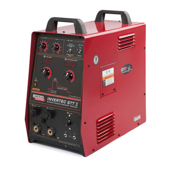
INVERTEC
10381,
10382,
10383
OPERATOR'S MANUAL
®
®
S T T
II
Premier Manufacturer of Industrial Motors
IM582
January, 1999
Advertisement
Table of Contents

Related Manuals for Lincoln INVERTEC STT 2


Summary of Contents for Lincoln INVERTEC STT 2
- Page 1 10381, For use with machines having Code Numbers: 10382, 10383 Safety Depends on You Lincoln arc welding and cutting equipment is designed and built with safety in mind. However, your overall safety can be increased by proper installation ... and thoughtful operation on your part.
-
Page 2: Safety
351040, Miami, Florida 33135 or CSA Standard W117.2-1974. A Free copy of “Arc Welding Safety” booklet E205 is available from the Lincoln Electric Company, 22801 St. Clair Avenue, Cleveland, Ohio 44117-1199. BE SURE THAT ALL INSTALLATION, OPERATION, MAINTENANCE AND REPAIR PROCEDURES ARE PERFORMED ONLY BY QUALIFIED INDIVIDUALS. -
Page 3: Electric Shock Can Kill
SAFETY ARC RAYS can burn. ELECTRIC SHOCK can 4.a. Use a shield with the proper filter and cover kill. plates to protect your eyes from sparks and 3.a. The electrode and work (or ground) circuits the rays of the arc when welding or observing are electrically “hot”... - Page 4 SAFETY WELDING SPARKS can CYLINDER may explode cause fire or explosion. if damaged. 6.a. Remove fire hazards from the welding area. 7.a. Use only compressed gas cylinders If this is not possible, cover them to prevent containing the correct shielding gas for the the welding sparks from starting a fire.
- Page 5 SAFETY zones où l’on pique le laitier. PRÉCAUTIONS DE SÛRETÉ 6. Eloigner les matériaux inflammables ou les recouvrir afin de Pour votre propre protection lire et observer toutes les instructions prévenir tout risque d’incendie dû aux étincelles. et les précautions de sûreté specifiques qui parraissent dans ce manuel aussi bien que les précautions de sûreté...
- Page 6 QUALITY product by Lincoln Electric. We want you Thank You to take pride in operating this Lincoln Electric Company product ••• as much pride as we have in bringing this product to you! NOTICE NO LICENSE RIGHT. EXPRESSLY RESERVED FROM THE SALE OF THE...
-
Page 7: Table Of Contents
TABLE OF CONTENTS Page Safety ........................i-iv Installation ......................Section A Technical Specifications ...................A-1 Location ........................A-2 Stacking ........................A-2 Tilting ........................A-2 Machine Grounding and High Frequency Interference Protection......A-2 Input Connections .....................A-2 Supply Connections ...................A-2 Input Cable Installation and Connection.............A-3 Ground Connection ....................A-3 Input Voltage Reconnect Procedure .................A-4 Output Connections ....................A-4 Wire Feeder Output Connections ...............A-4 Operation ......................Section B... -
Page 8: Installation
INSTALLATION TECHNICAL SPECIFICATIONS –Invertec STT II INPUT- THREE PHASE ONLY STANDARD VOLTAGE INPUT CURRENT AT RATED OUTPUT 208/230/460/3/60 HZ 32/30/16 200/220/380/415/440/3/50/60 HZ 33/30/18/17/16 RATED OUTPUT DUTY CYCLE AMPS VOLTS AT RATED AMPS 60% Duty Cycle 100% Duty Cycle OUTPUT CURRENT RANGE OPEN CIRCUIT VOLTAGE AUXILIARY POWER Peak Current... -
Page 9: Location
INSTALLATION Read and understand entire Installation MACHINE GROUNDING AND HIGH Section before starting installation. FREQUENCY INTERFERENCE PROTECTION WARNING The machine may not be suitable for use in an envi- ELECTRIC SHOCK can kill. ronment where high frequency is present. For exam- •... -
Page 10: Input Cable Installation And Connection
INSTALLATION CASE BACK NAMEPLATE INPUT CABLE ENTRY ACCESS & CABLE STRAIN RELIEF FIGURE A.1 CASE BACK INPUT CABLE INSTALLATION AND CON- 5. Connect the three phase line con- NECTION ductors to the power switch termi- nals labeled U, V and W. Tighten A cable strain relief is provided at the supply line entry the connections to 3.0 Nm. -
Page 11: Input Voltage Reconnect Procedure
INSTALLATION FIGURE A.2 RECONNECT PANEL INPUT VOLTAGE RECONNECT 380 or 415 VAC 1. Open reconnect panel PROCEDURE access door on wrap-around. 2. Move input voltage switch As shipped from the factory, multiple voltage to Voltage = 380 -460V position. (208/230/460 VAC) or (200/220/380 - 415/440 VAC) 3. -
Page 12: Operation
OPERATION OPERATING INSTRUCTIONS Read and understand entire section before operating machine. GENERAL WARNINGS SAFETY PRECAUTIONS WARNING ELECTRIC SHOCK can kill. • Do not touch electrically live parts or electrode with skin or wet clothing. • Insulate yourself from work and ground. -
Page 13: General Description
OPERATION GENERAL DESCRIPTION High temperature Class H insulation. • The Invertec STT II is a 225-ampere inverter based Protection circuits and ample safety margins prevent • arc welding power source specifically designed for the damage to the solid state components from tran- STT welding process. -
Page 14: Operational Features And Controls
OPERATION OPERATIONAL FEATURES AND CONTROLS All operator controls are located on the case front of the Invertec STT II. Refer to Figure B.1 for locations. FIGURE B.1 CASE FRONT CONTROLS 1. POWER SWITCH: Turns output 3B.PEAK CURRENT DISPLAY METER: This power ON and OFF. -
Page 15: Welding Operation
OPERATION 6. WIRE SIZE SELECT SWITCH: This toggle switch 13. 115V AUXILIARY POWER CIRCUIT BREAKER selects between electrode diameters of .035” (1 (Not on European Models): The 115 VAC mm) and smaller or .045” (1.2 mm) and larger. The supply is protected from excessive current .035”... -
Page 16: Welding Parameters And Guidelines
OPERATION WELDING PARAMETERS AND GUIDE- Adjusting this level to low will cause wire stubbing and also poor wetting of the weld metal. This is similar to LINES a low voltage setting on a standard CV machine The Invertec STT II is neither a constant current (CC) Adjust Bead Shape using Background Current nor a constant voltage (CV) power source. - Page 17 OPERATION WELDING PROCEDURES FOR STT II - (Stainless Steel) Horizontal Fillet (See Table B.3 and B.4) (Steel) Horizontal Fillet (See Table B.1 and B.2) DIRECTION DIRECTION 75° TRAVEL 75° TRAVEL TOP VIEW TOP VIEW DIRECTION 45° 75° TRAVEL DIRECTION 45° 75°...
-
Page 18: Accessories
ACCESSORIES OPTIONS / ACCESSORIES GROUND inputs on this connector rather than from the front panel controls. If this short is removed, the front panel controls will be active. By adding a K940 SENSE LEADS: These leads are used to accu- switch between pins... -
Page 19: Ln-742 Or Stt-10 Wire Feeder Connection Instructions
ACCESSORIES LN-742 or STT-10 WIRE FEEDER 3. Connect the electrode lead (Twist-Mate) to (+) out- put terminal on STT II. CONNECTION INSTRUCTIONS 4. Connect the other end of electrode lead (Step #3) The LN-742 or STT-10 is the recommended wire feed- and the ARC SENSE LEAD (lead with ring lug, step er for use with the Invertec STT II. - Page 20 ACCESSORIES CONNECTION DIAGRAM - INVERTEC STT II WARNING Turn off input power to the Welding Power source using the disconnnect switch at the fuse box before connecting the wire feeder. Only qualified persons should install, ELECTRIC use or service this machine. SHOCK CAN KILL WIRE FEEDER...
-
Page 21: Maintenance
MAINTENANCE 5. Locate the two capacitor terminals (large WARNING hex head cap screws) shown in Figure Failure to follow this D.1. capacitor discharge proce- dure can result in electric 6. Use safety glasses, electrically insulated shock. gloves and insulated pliers. Hold body of the resistor and connect resistor leads INPUT FILTER CAPACITOR across the two capacitor terminals. -
Page 22: Preventive Maintenance
MAINTENANCE PREVENTIVE MAINTENANCE • Input Filter Capacitors 1. Perform the following preventive mainte- • Output Terminals nance procedures at least once every six months. It is good practice to keep a pre- • Lower base compartment ventive maintenance record; a record tag attached to the machine works best. -
Page 23: Troubleshooting
HOW TO USE TROUBLESHOOTING GUIDE WARNING Service and Repair should only be performed by Lincoln Electric Factory Trained Personnel. Unauthorized repairs performed on this equipment may result in danger to the technician and machine operator and will invalidate your factory warranty. For your safety and to avoid Electrical Shock, please observe all safety notes and precautions detailed throughout this manual. - Page 24 CAUTION If for any reason you do not understand the test procedures or are unable to perform the tests/repairs safely, contact your Local Lincoln Authorized Field Service Facility for technical troubleshooting assistance before you proceed. INVERTEC STT II...
- Page 25 CAUTION If for any reason you do not understand the test procedures or are unable to perform the tests/repairs safely, contact your Local Lincoln Authorized Field Service Facility for technical troubleshooting assistance before you proceed. INVERTEC STT II...
- Page 26 CAUTION If for any reason you do not understand the test procedures or are unable to perform the tests/repairs safely, contact your Local Lincoln Authorized Field Service Facility for technical troubleshooting assistance before you proceed. INVERTEC STT II...
- Page 27 Service Facility. CAUTION If for any reason you do not understand the test procedures or are unable to perform the tests/repairs safely, contact your Local Lincoln Authorized Field Service Facility for technical troubleshooting assistance before you proceed. INVERTEC STT II...
- Page 28 CAUTION If for any reason you do not understand the test procedures or are unable to perform the tests/repairs safely, contact your Local Lincoln Authorized Field Service Facility for technical troubleshooting assistance before you proceed. INVERTEC STT II...
-
Page 29: Diagrams
DIAGRAMS INVERTEC STT II... - Page 30 DIAGRAMS INVERTEC STT II...
- Page 31 Month Year USE THIS FORM TO ORDER: Order from: BOOK DIVISION, The Lincoln Electric Company, 22801 St. Clair Avenue, Cleveland, Ohio 44117-1199 for fastest service, FAX this completed form to: 216-361-5901 BOOKS OR FREE INFORMATIVE CATALOGS Telephone: 216-383-2211 or, Lincoln Welding School...
- Page 32 Do not touch electrically live parts or Keep flammable materials away. Wear eye, ear and body protection. WARNING electrode with skin or wet clothing. Insulate yourself from work and ground. Spanish No toque las partes o los electrodos Mantenga el material combustible Protéjase los ojos, los oídos y el AVISO DE bajo carga con la piel o ropa moja-...
- Page 33 Keep your head out of fumes. Turn power off before servicing. Do not operate with panel open or WARNING Use ventilation or exhaust to guards off. remove fumes from breathing zone. Spanish Los humos fuera de la zona de res- Desconectar el cable de ali- No operar con panel abierto o AVISO DE...
Need help?
Do you have a question about the INVERTEC STT 2 and is the answer not in the manual?
Questions and answers
What are the recommended parameters to weld all with a Lincoln invertec STT 2 WELDER
The recommended welding parameters for the Lincoln Invertec STT II welder are:
- Rated output: 225 amps, 29 volts
- Duty cycle: 60% on a ten-minute basis
- Capable of higher duty cycles at lower output currents
If the duty cycle is exceeded, a thermal protector will shut the machine off.
This answer is automatically generated
I find that there is far too much burn back on this machine
To reduce burn back on the Lincoln INVERTEC STT 2, adjust the Wire Feed Speed, Peak Current, and Background Current settings. Increasing the Wire Feed Speed ensures proper electrode extension, while adjusting Peak Current helps control the arc length. Proper Contact Tip to Work Distance also affects burn back, so maintaining the correct spacing can help minimize the issue.
This answer is automatically generated