
Subscribe to Our Youtube Channel
Related Manuals for BCM RX87Q


Summary of Contents for BCM RX87Q
- Page 1 RX87Q Intel® Q87 μATX Motherboard Supports 22nm Generation Core i7/i5/i3, Pentium® μATX Motherboard User’s Manual Edition 1.10 – Jul, 2014...
- Page 2 Copyright Notice Copyright 2011 BCM Advanced Research, ALL RIGHTS RESERVED. No part of this document may be reproduced, copied, translated, or transmitted in any form or by any means, electronic or mechanical, for any purpose, without the prior written permission of the original manufacturer.
- Page 3 Disclaimer BCM Advanced Research reserves the right to make changes, without notice, to any product, including circuits and/or software described or contained in this manual in order to improve design and/or performance. BCM Advanced Research assumes no responsibility or liability for the use of the described...
-
Page 4: Bcm Customer Services
BCM has come to be known. Your satisfaction is our primary concern. Here is a guide to BCM customer services. To ensure you get the full benefit of our services, please follow the instructions below carefully. -
Page 5: Product Warranty
Because of BCM high quality-control standards and rigorous testing, most of our customers never need to use our repair service. If any of BCM products is defective, it will be repaired or replaced at no charge during the warranty period. For out-of-warranty repairs, you will be billed according to the cost of replacement materials, service time, and freight. - Page 6 This manual describes in detail the BCM RX87Q Main board. We strongly recommend that you study this manual carefully before attempting to interface with RX87Q or change the standard configurations. Whilst all the necessary information is available in this manual we would recommend that unless you are confident, you contact your supplier for guidance.
-
Page 7: Table Of Contents
Contents Chapter 1: System Setup ............... Welcome! ............................11 Packing Contents .......................... 11 Features System Block Diagram ....................12 1.3.1 Product Highlights ......................... 13 Before you proceed ........................14 Mainboard Overview ........................15 1.5.1 Placement Direction ........................15 1.5.2 Mounting Holes ..........................16 1.5.3 Onboard LEDs .......................... - Page 8 1.10.2 Fan Power Connectors: CPU_FAN1, CHA_FAN1, SYS_FAN1 ........... 39 1.10.3 Chassis Intrusion Switch Connector: JCASE1 ................40 1.10.4 Front Panel Audio Connector: FPAUD1 ..................40 1.10.5 Amplifier Connector: JAMP1 ......................41 1.10.6 Front USB2.0 Headers: USB45, USB67, USB89, USB1011, USB1213 ........42 1.10.7 Serial Port Connectors: COM1, COM2, COM3, COM4 ..............
- Page 9 Mainboard Specifications Model RX87Q Processor Socket LGA1150 supports 4 Generation Core i7/i5/i3 CPU (up to 84W) Chipset Intel® 4 x 240 Pin DIMM sockets supports DDR3 memory module (1.5V) 1333 (PC3-16000)/ Memory Display Intel® GMA HD (Must use Intel Processor that provides “Intel HD Graphics”...
- Page 10 Onboard I/O Headers SATA 6 x Std. SATA Connectors 5 x USB Headers (10 ports on headers) RS232 6 x Headers 1 x Header Front Audio 1 x Header Amplifier 1 x Header Front Panel 1 x Header Fan Header 3 x Headers (4-pins) Chassis Intrusion Header 1 x Header...
-
Page 11: Chapter 1: System Setup
This chapter describes the mainboard features and the new technologies it supports 1.1 Welcome! The mainboard delivers a host of new features and latest technologies, making it another line of BCM long life mainboards! Before you start installing the mainboard, and hardware devices on it, check the items in your package with the list below. - Page 12 1.3 Features RX87Q block Diagram...
-
Page 13: Product Highlights
ME Lock overwrite The RX87Q has implement ME lock to avoid ME firmware accidentally overwrite (recommended by Intel for manufacture), after ME lock is implement to the boards, BIOS programing utility will not be able to overwrite ME region, if ME... - Page 14 when BIOS update is complete (see Page 44).
-
Page 15: Before You Proceed
1.5 Before you proceed Take note of the following precautions before you install mainboard components or change any mainboard settings. • Unplug the power cord from the wall socket before touching any component inside the system. • Use a grounded wrist strap or touch a safely grounded object or to a metal object, such as the power supply case, before handling components to avoid damaging them due to static electricity. -
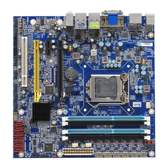
Page 16: Mainboard Overview
Mainboard Overview Before you install the mainboard, study the configuration of your chassis to ensure that the mainboard fits into it. Make sure to unplug the power cord before installing or removing the mainboard. Failure to do so can cause you physical injury and damage mainboard components. 1.6.1 Placement Direction When installing the mainboard, make sure that you place it into the chassis in the correct orientation. -
Page 17: Mounting Holes
1.6.2 Mounting Holes Place the screws into the mounting holes indicated by red squares to secure the mainboard to the chassis. Do not over-tighten the screws! Doing so may damage the mainboard. -
Page 18: Onboard Leds
1.6.3 Onboard LEDs The mainboard comes with a “Power On LED” (green) to indicate the system power status. When power cable is connect to the power source. The “Power LED” lights will be on to indicate that the system has standby power. -
Page 19: Mainboard Layout
1.6.4 Mainboard Layout • Back Panel:... -
Page 20: Layout Content List
1.6.5 Layout Content List 1.6.5.1 Slots Label Function Note Page DIMM1 240-pin DIMM slot 1 1. If there is only one memory module being installed in the system, install it on this slot first. 2. If there are only two memory modules being installed in the system, install these 2 modules on “DIMM1”... -
Page 21: Internal Headers
1.6.5.3 Internal Headers Label Function Note Page PWR1 ATX Power Connector 2 x 2 header ATX1 ATX Power Connector 12 x 2 header SATA1 Serial ATA Connectors 1~6 7-pin header SATA2 SATA3 SATA4 SATA5 SATA6 CPU_FAN (CN7) CPU Fan Connector 4 x 1 wafer, pitch 2.54mm CHA_FAN1 (CN3) Chassis Fan Connector... -
Page 22: Back Panel Connectors
1.6.5.4 Back Panel Connectors Label Function Note Page KBMS PS/2 keyboard and mouse 6-pin Mini-Din VGA/ DVI VGA Connector x 1 D-sub 15-pins, female DVI Connector x 1 Dual Link DVI-D; 24-pins DP1/ DP2 Display Port x 2 (COM1/ COM2) LAN1/ LAN2 RJ-45 Ethernet Connector x 2 USB3.0 Connector x 4... -
Page 23: Central Processing Unit (Cpu)
PnP cap/socket pins/mainboard components. BCM will shoulder the cost of repair only, if the damage is shipment/ transit-related. • Keep the PnP cap after installing the mainboard. BCM will process Return Merchandise Authorization (RMA) requests only if the mainboard comes with the cap installed on the LGA1150 socket. -
Page 24: Installing The Cpu
1.7.1 Installing the CPU To install a CPU 1. Locate the CPU socket (LGA1150 Socket) on the mainboard. 2. Unlatch the “CPU Socket Lever” by pressing the lever down and move it away from the main structure of the socket. To prevent damage to the socket pins, do not remove the “CPU Socket Cover”... - Page 25 3. Lift the load lever up in the direction of the arrow to a 135˚ angle, so the metal “CPU Socket Cover” can also be lifted. 4. The CPU socket has a plastic protection cap installed on it (black color, a.k.a. “CPU Socket Cover”, or “PnP cap”) in order to protect the socket pins from damage.
- Page 26 5. There are two notches on the CPU itself (one on each side), and there are two “Socket Alignment keys” on the CPU socket as well. Line up the two CPU notches with the “Socket Alignment Keys” on the socket, and insert the CPU into the CPU socket slowly. Visually inspect if the CPU is seated into the CPU socket evenly.
- Page 27 6. Close the “CPU Socket Cover” by lowering down the “CPU Socket Lever”. Make sure the “CPU Socket Front Plates” are sliding underneath the “Shoulder Screw Cap”. 8. Secure the “CPU Socket Cover” by keep pressing down the “CPU Socket Lever” and move it toward and underneath the “Load Plate Tab”.
-
Page 28: Installing The Cpu Heatsink And Fan
1.7.2 Installing the CPU Heatsink and Fan The Intel LGA1150 processor requires a specially designed heatsink and fan assembly to ensure optimum thermal condition and performance. • When you purchase a boxed Intel® processor, the package includes the CPU fan and heatsink assembly. - Page 29 Push down two fasteners at a time in a diagonal sequence to secure the heatsink and fan assembly in place 3. Connect the CPU fan cable to the connector on the motherboard labeled “CPU_FAN1”. Do not forget to connect the CPU fan connector. Insufficient air flow inside the system chassis may damage the mainboard components.
-
Page 30: Uninstalling The Cpu Heatsink And Fan
1.7.3 Uninstalling the CPU Heatsink and Fan. To uninstall the CPU heatsink and fan: 1. Disconnect the CPU fan cable from the connector on the mainboard. 2. Rotate each fastener counterclockwise. 4. Pull up two fasteners at a time in a diagonal sequence to disengage the heatsink and fan assembly from the mainboard. - Page 31 5. Rotate each fastener clockwise to ensure correct orientation when reinstalling. The narrow end of the groove should point outward after resetting. (The photo shows the groove shaded for emphasis.)
-
Page 32: System Memroy
1.8 System Memory 1.8.1 Overview The mainboard comes with four 240-pin Double Data Rate 3 (DDR3) Dual Inline Memory Modules (DIMM) slots. You may use 1600MHz (PC3-12800, 1333MHz (PC3-10600); Non-ECC, Un-buffered 1.5V DDR3 memory modules on this board (8GB maximum for each slot). DDR3 DIMMs are notched differently to prevent installation on a DDR2 DIMM socket. -
Page 33: Configurations Of Supported Memory Modules (Non-Ecc, Unbuffered)
1.8.2 Configurations of Supported Memory Modules (Non-ECC, Unbuffered) 1.8.3 Dual-Channel Mode Population Rule In Dual-Channel mode, the memory modules can transmit and receive data with two data bus lines simultaneously. Enabling Dual-Channel mode can enhance the system performance. Please refer to the following illustrations for population rules under Dual-Channel mode. -
Page 34: Installing Dimm
• Install at least 1GB of memory module onboard. • When install only one DDR3 memory module, install it on “DIMM1” slot ONLY. • When install only two DDR3 memory module, install them on “DIMM1” and “DIMM3” slots ONLY. • In dual-channel configurations, install only identical (the same type, and size) DDR3 memory module paired for each channel. -
Page 35: Removing A Dimm
1. A DDR3 memory module is keyed with a notch so that it fits in only one direction. 2. DO NOT force the memory module into the socket in order to avoid damaging the memory module and the slot. 3. DDR3 memory modules are not interchangeable with DDR or DDR2. 4. -
Page 36: Power Supply
1.9 Power Supply 1.9.1 ATX Power Connectors: ATX1, PWR1 These ATX power connectors provide connections from power supply unit (PSU) to the mainboard. Both connectors need to be installed in order for the mainboard to function properly. The power supply plugs are designed to fit with these ATX power connectors in one orientation only. To connect these power supply plugs;... -
Page 37: Back Panel
1.10 Back Panel 1.10.1 Back Panel Connectors Item Name Function Description KBMS PS/2 Mouse The port is for a PS/2 mouse. Connector Display Port 2 Provides “displayport” type connection to monitor. VGA Video Port The VGA15-pin Connector. LAN1/ Gigabit LAN This port allows Gigabit connection to a Local Area LAN2 (RJ-45) - Page 38 Out. AUDIO Microphone port This port connects a microphone. (Pink) USB 3.0 These two 4-pin Universal Serial Bus (USB) ports Connectors are available for connecting USB 3.0/ 2.0 devices. USB 3.0 These two 4-pin Universal Serial Bus (USB) ports Connectors are available for connecting USB 3.0/ 2.0 devices.
-
Page 39: Connectors/Headers
1.11 Connectors/ Headers 1.11.1 Serial ATA Connectors: SATA3.0: SATA3, SATA4, SATA5, SATA6 SATA3.0 standard, which is backward compatible with SATA2.0 Please do not fold the Serial ATA cable into 90-degree angle. Otherwise, data loss may occur during data transmission. - Page 40 1.11.2 Fan Power Connectors: CN7, CN3, CN4 The fan power connectors support system cooling fan with +12V. When connecting the wire to these fan connectors, please note that the red wire is designated as “Power” and should be connected to “+12V” pin; the black wire is designated as “Ground”...
- Page 41 1.11.3 Chassis Intrusion Switch Connector: INTR1 This connector connects to a 2-pin chassis switch. If the chassis is opened, the switch will be short. The system will record this status and show a warning message on the screen. To clear the warning message, you must enter the BIOS and clear the record. 1.11.4 Front Panel Audio Connector: J_AUDIO1 This connector allows you to connect the front panel audio and is compliant with Intel®...
- Page 42 1.11.5 Amplifier Connector: CN14 This header provided amplified audio signals to external speakers (2-channels). The dB level can be adjusted under BIOS.
-
Page 43: Serial Port Connectors: Com1, Com2, Com3, Com4
1.11.6 Front USB2.0 Headers: JUSB1, JUSB2, JUSB3, JUSB4, JUSB5 This connector is compliant with Intel® I/O Connectivity Design Guide, which is ideal for connecting high-speed USB peripherals such as USB HDD, USB digital cameras, USB MP3 players, USB printers, etc. Be sure the pins of VCC and GND is connected to the connector correctly. -
Page 44: Lpt Port Connector: Lpt1
1.11.8 LPT Port Connector: CN11 1.11.9 Front Panel Connectors: FP_1 These connectors are for electrical connections to the front panel switches and LEDs. The “F_PANEL1” connector is compliant with Intel® Front Panel I/O Connectivity Design Guide. -
Page 45: Me Lock
1.11.10 ME Lock Overwrite: J1 The “ME Lock Overwrite” header provides an option to program the entire BIOS even when the ME region had ME lock applied during board manufacturing to prevent unintentionally write to BIOS ME region, ME lock is recommended by Intel for system manufacture. 1.11.11 Digital I/O Connector: CN6 This header provides connections to GPIO ports. -
Page 46: Jumpers
1.12 Jumpers 1.12.1 Clear CMOS Jumper: JP5 There is a CMOS RAM onboard that has a power supply from an external battery to keep the data of system configuration. For normal state (default), the jumper is set on pin location 1 and 2. To clear the CMOS, set the jumper to pin location 2 and 3 for at least 30 seconds while the system is off. -
Page 47: Com1 Rs232/Rs422/Rs485 Select: Jp1, Jp2, Jp3
1.12.2 COM1 RS232/ RS422/ RS485 Select: JP2, JP3, JP4 These jumpers provide combinations for RS232 (default), or RS422, or RS485 transfer mode on COM1 (rear I/O). 1.12.3 COM1, COM2, COM3, COM4, COM5 and COM6 Ring-in/ +12V/ +5V Select: Com_JP1, COM_JP2, COM_JP3, COM_J4, COM_JP5, Power COM_JP6 These headers provide ring-in, or 5V, or 12V on the com ports. - Page 48 1.12.4 ATX/AT Mode Selection: AT_ATX_1 This header provides the option to boot the system in the form of ATX mode (default) or AT mode. When the system is set in AT mode, the system power on/off will be controlled directly by the power switch on power supply.
-
Page 49: The Expansion Slots
1.13 The Expansion Slots In the future, you may need to install expansion cards. The following sub-sections describe the expansion slots and the expansion cards that they support. Make sure to unplug the power cord before adding or removing expansion cards. Failure to do so may cause you physical injury and damage mainrboard components. -
Page 50: Pci-Ex16 Slot: Slot1
▪ The PCI Express x8 (PCI-E x8) supports up to 2.0GB/s transfer rate. ▪ The PCI Express x4 (PCI-E x4) supports up to 1.0GB/s transfer rate. ▪ The PCI Express x1 (PCI-E x1) supports up to 250MB/s transfer rate. 1.13.3.1 PCI-E x 16 Slot: SLOT1 The PCIEX16 slot supports PCI-E x16 graphic card. -
Page 51: Chapter 2: Starting Up The System
Chapter 2: Starting Up the System 2 Starting Up Your System After all connections are made, close your computer case cover. Be sure all the switches are off, and check that the power supply input voltage is set to the local voltage, usually in-put voltage is 220V240V or 110V120V depending on your country’s voltage used. - Page 52 If you wish to boot from a different bootable device other than the default arrangement under the BIOS, you may press <F11> key during the system power-on (post); a menu with all detected bootable devices which are attached to the system will be displayed. Then you may select the desired first bootable device from this menu.
-
Page 53: Bios Setup Program
Chapter 3: BIOS SETUP Option User Guide 3 BIOS Setup Program This motherboard supports a programmable firmware chip that you can update using the provided utility. Use the BIOS Setup program when you are installing a motherboard, reconfiguring your system, or prompted to “Run Setup.” This section explains how to configure your system using this utility. -
Page 54: Legend Box
purposes only, and may not exactly match what you see on your screen. Visit the system builder’s website to download the latest BIOS file for this motherboard 3.1 Legend Box The keys in the legend bar allow you to navigate through the various setup menus Key(s) Function Description ←... -
Page 55: Bios Menu Screen
accidentally make unwanted changes to any of the fields, press <F9> to load the optimal default values. While moving around through the Setup program, note that explanations appear in the Item Specific Help window located to the right of each menu. This window displays the help text for the currently highlighted field. -
Page 56: Main Setup
3.2 Main Setup This menu gives you an overview of the general system specifications. The BIOS automatically detects the items in this menu. Use this menu for basic system configurations, such as time, date etc. BIOS Information Displays the auto-detected BIOS information. ... -
Page 57: Advanced Bios Setup
3.3 Advanced BIOS Setup Select the Advanced tab from the setup screen to enter the Advanced BIOS Setup screen. You can select any of the items in the left frame of the screen, such as Chipset configuration, to go to the sub menu for that item. You can display an Advanced BIOS Setup option by highlighting it using the <Arrow>... -
Page 58: Pci Subsystem Setting
3.3.1 PCI Subsystem Setting The PCI PnP menu items allow you to change the advanced settings for PCI/PnP devices. The menu includes setting IRQ and DMA channel resources for either PCI/PnP or legacy ISA devices, and setting the memory size block for legacy ISA devices. ... -
Page 59: Acpi Settings
3.3.2 ACPI Settings ACPI Sleep State [S3 (suspend to RAM)] Select the highest ACPI sleep state the system will enter the SUSPEND button is press. Configuration options: [S1 (CPU Stop Clock)] [S3 (suspend to RAM )] S3 Video Repost [Disabled] This setting allows you to determine whether to invoke VGA BIOS POST on S3/STR resume. -
Page 60: Trusted Computing
3.3.3 Trusted computing Configuration Security Device Support [Disabled] Enable or disable TPM support. Configuration options: [Disabled] [Enabled] Current Status Information Displays the TPM status information... -
Page 61: Cpu Configuration
3.3.4 CPU configuration CPU configuration Displays the CPU information Hyper-threading [Enabled] Enabled or disabled Hyper-Treading Technology Configuration options: [Disabled] [Enabled] Active Processor Cores [All] Select the numbers of cores in each processor package. Configuration options: [All] [1] [2] [3] [4] [5] [6] [7], It depends on each CPU type. - Page 62 Intel Virtualization Technology [Enabled] When enable, a VMM can utilize the additional hardware capabilities provided by Vanderpool Technology. Configuration options: [Disabled] [Enabled] EIST [Enabled] Enable or disable speed step. Configuration options: [Disabled] [Enabled] Turbo Mode [Enabled] Enable or Disable CPU Turbo Mode. Configuration options: [Disabled] [Enabled] CPU C States [Enabled] Enable or Disable CPU C states...
- Page 63 Configuration options: [Disabled] [Enabled] CPU C3 State Support [Enabled] Use this to enable or disable CPU C3 (ACPI C2) report to OS. Configuration options: [Disabled] [Enabled] CPU C6 State Support [Disabled] Use this to enable or disable CPU C6 (ACPI C3) report to OS. Configuration options: [Disabled] [Enabled] ...
-
Page 64: Sata Configuration
3.3.5 SATA Configuration Serial-ATA Controller(s) [Enable] Enabled/Disabled Serial-ATA Controller 0 Configuration options: [Disabled] [Enabled] SATA Mode [IDE] Determines how SATA controller(s) operate. Configuration options: [IDE][AHCI][RAID]... - Page 65 3.3.6 PCH-FW Configuration Display ME firmware information...
-
Page 66: Amt Configuration
3.3.7 AMT Configuration Intel AMT [Enabled] Enable/Disable Intel Active Management Technology. Configuration options: [Disabled] [Enabled] Un-Configure ME [Disabled] Un-Configure ME without password. Configuration options: [Disabled] [Enabled]... - Page 67 3.3.8 USB Configuration USB Configuration Parameters USB Device Display how many devices are connected. Legacy USB Support [Enabled] Enables Legacy USB support. AUTO option disables legacy support if no USB devices are connected. DISABLE option will keep USB devices available only for EFI applications. Configuration options: [Enabled] [Disabled][Auto]...
- Page 68 3.3.9 Super IO Configuration System Super IO Chip Parameters. Super IO Configuration NCT6776 Super IO Chip [NCT6776F]...
-
Page 69: Serial Port 1 Configuration
3.3.10 Serial Port 1 configuration Set Parameters of Serial Port 1 Serial Port [Enable] Enable or Disable Serial Port. Configuration options: [Disabled] [Enabled] Device Setting [IO=3F8h; IRQ=4] Change Setting[Auto] Select an optimal setting for Super IO device. Configuration options: [Auto] [IO=3F8h;... -
Page 70: Serial Port 2 Configuration
3.3.11 Serial Port 2 configuration Set Parameters of Serial Port 2 Serial Port 2 Configuration Serial Port [Enable] Enable or Disable Serial Port. Configuration options: [Disabled] [Enabled] Device Setting [IO=3E8h; IRQ=5] Change Setting[Auto] Select an optimal setting for Super IO device. Configuration options: [Auto] [IO=3E8h;... -
Page 71: Serial Port 3 Configuration
3.3.12 Serial Port 3 configuration Set Parameters of Serial Port 3 Serial Port 3 Configuration Serial Port [Enable] Enable or Disable Serial Port. Configuration options: [Disabled] [Enabled] Device Setting [IO=2E8h; IRQ=5] Change Setting[Auto] Select an optimal setting for Super IO device. Configuration options: [Auto] [IO=2E8h;... -
Page 72: Serial Port 4 Configuration
3.3.13 Serial Port 4 configuration Set Parameters of Serial Port 4 Serial Port 4 Configuration Serial Port [Enable] Enable or Disable Serial Port. Configuration options: [Disabled] [Enabled] Device Setting [IO=2E0h; IRQ=10] Change Setting[Auto] Select an optimal setting for Super IO device. Configuration options: [Auto] [IO=2E0h;... -
Page 73: Serial Port 5 Configuration
3.3.14 Serial Port 5 configuration Set Parameters of Serial Port 5 Serial Port 5 Configuration Serial Port [Enable] Enable or Disable Serial Port. Configuration options: [Disabled] [Enabled] Device Setting [IO=2F0h; IRQ=10] Change Setting[Auto] Select an optimal setting for Super IO device. Configuration options: [Auto] [IO=2F0h;... -
Page 74: Parallel Port Configuration
3.3.15 Parallel Port Configuration Parallel Port [Enable] Use this item to enable or disable the onboard parallel port. Configuration options: [Disabled] [Enabled] Change Settings [Auto] Use this item to select an optional setting for Super IO device. Configuration Options: [Auto] [IO=378h; IRQ=7] [IO=378h; IRQ=6,7,9,11,12] [IO=278h; IRQ=6,7,9,11,12] ... -
Page 75: Watchdog Configuration
Chassis Opened Warning [Disabled] Select whether to enable Chassis Intrusion Detection. Configuration options: [Disabled] [Enabled] 3.3.16 WatchDog Configuration WatchDog Count Mode [Second(s) Mode] Select Watch Dog Count Mode. Configuration options: [Second(s) Mode [Minute(s) Mode] WatchDog TimeOut Value [0] Timer will start to count from end of POST. - Page 76 3.3.17 H/W Monitor PC Health Status Display system health status...
-
Page 77: Smart Fan
3.3.18 Smart Fan Smart Fan Function [Enable] Smart Fan Function enable/disable Configuration options: [Disabled] [Enabled]... -
Page 78: Smart Fan Mode Configuration
3.3.19 Smart Fan Mode Configuration Smart Fan Mode configuration SYS Smart Fan1 Target [Disabled] SYS Smart Fan1 Target Temperature Configuration options: [Disabled] [40 C] [45 C] [50 C] [55 C] [60 C] [65 C] [70 C] SYS Smart Fan2 Target [Disabled] SYS Smart Fan2 Target Temperature Configuration options: [Disabled] [40 C] [45 C] [50 C] [55 C] [60 C] [65 C] [70 C] ... -
Page 79: Option Rom Policy
3.3.20 Option ROM Policy Launch Storage OpROM [Legacy only] Enable or Disable Boot Option For Legacy Mass Storage Devices with Option ROM Configuration options: [Do not launch] [UEFI only] [Legacy only] Other PCI Device ROM priority [UEFI OpROM] Configuration options: [UEFI OpROM] [Legacy OpROM]... - Page 80 3.3.21 Intel RC Driver Version Detail Displays Version String for drivers...
- Page 81 3.4 Chipset...
- Page 82 3.4.1 PCH-IO Configuration PCH-IO Configuration LAN1 Controller [Enable] Enable/Disable LAN1 Controller Configuration options: [Disabled] [Enabled] LAN1 Option-ROM [Disable] Enable/Disable LAN1 boot option for legacy network devices. Configuration options: [Disabled] [Enabled] LAN2 Controller [Enable] Enable/Disable LAN1 Controller Configuration options: [Disabled] [Enabled] ...
-
Page 83: Pci Express Configuration
Restore AC Power Loss [Always Off] Specify what state to go to when power is re-applied after a power failure. Configuration options: [Always Off] [Always On] [Last state] 3.4.1.1 PCI Express Configuration... - Page 84 3.4.1.2 PCI Express Root Port 1 ASPM Support [Disabled] Set the ASPM Level1: Force L0s – Force all links to L0s State, AUTO – BIOS auto configure, Disabled – Disables ASPM Configuration options: [Disabled] [L0s] [L1] [L0sL1] [AUTO] PCIe Speed [Auto] Select PCI Express port speed.
- Page 85 3.4.1.3 PCI Express Root Port 5 PCI Express Root Port 5 [Enabled] Control the PCI Express Root Port. Configuration options: [Disabled] [Enabled] ASPM Support [Disabled] Set the ASPM Level1: Force L0s – Force all links to L0s State, AUTO – BIOS auto configure, Disabled – Disables ASPM Configuration options: [Disabled] [L0s] [L1] [L0sL1] [AUTO] ...
- Page 86 Configuration options: [Disabled] [Enabled] 3.4.1.4 USB Configuration USB3.0 Support [Enabled] Enable/Disable USB 3.0 support Configuration options: [Disabled] [Enabled] USB ports per-port disable cont [Disabled] Control each of the USB ports (1~14) disabling. Configuration options: [Disabled] [Enabled]...
-
Page 87: Pch Azalia Configuration
3.4.1.5 PCH Azalia Configuration Azalia [Enabled] Control Detection of the Azalia device. Configuration options: [Disabled] [Enabled]... - Page 88 3.4.2 System Agent (SA) Configuration VT-d [Disable] Set VT-d Enable or Disable Configuration options: [Disabled] [Enabled]...
-
Page 89: Graphics Configuration
3.4.2.1 Graphics Configuration Primary Display [Auto] Select which of IGFX/PEG/PCI Graphics device should be Primary Display or select SG for Switchable Gfx. Configuration options: [AUTO][IGFX][PEG] Internal Graphics [Auto] Keep IGD enabled based on the setup options. Configuration options: [Auto] [Disabled] [Enabled] ... - Page 90 Configuration options: [128M][256M][MAX]...
-
Page 91: Lcd Control
3.4.2.1.1 LCD Control Primary IGFX Boot Display [VBIOS Default] Select the Video Device that will be activated during POST. Configuration options: [VBIOS Default] [CRT] [Display Port1] [DVI-D] [Display Port2]... -
Page 92: Nb Pcie Configuration
3.4.2.2 NB PCIe Configuration PEG0 – Gen X [Auto] Configure PEG0 Gen1~Gen3 Configuration options: [Auto][Gen1][Gen2][Gen3] Enable PEG [Auto] To enable/Disable the PEG slot. Configuration options:[Auto][Enabled][Disabled] Detect Non-Compliance Device [Disabled] Detect Non-Compliance PCI Express Device in PEG. Configuration options: [Disabled] [Enabled] PEG1 - ASPM [Disabled] ... - Page 93 3.4.2.3 Memory Information Display Memory Information...
- Page 94 3.5 Boot Boot Configuration Setup Prompt Timeout [1] Number of seconds to wait for setup activation key. 65535(0xFFFF) means indefinite waiting. Bootup NumLock State [On] Select the keyboard NumLock state Configuration options: [On] [Off] Quiet Boot [Disabled] Enables or disables Quiet Boot option.
- Page 95 3.6 Security Administrator Password Set setup Administrator Password User Password Set User Password...
- Page 96 3.7 Save & Exit Save changes and Exit Exit system setup after saving the changes. Discard changes and Exit Exit system setup without saving the changes. Save changes and Reset Reset the system after saving the changes. ...
- Page 97 Boot Mode BIOS default related to RAID function Boot Mode BIOS Mode (aka Legacy Mode) UEFI Mode Boot ROM Format PCI or ISA ROM, 16-bit UEFI Driver, 32-bit or 64-bit UI for Q87 RAID Intel RAID ROM, CTRL+I “MISC” page in SETUP features Partition Type of Boot Drive...
Need help?
Do you have a question about the RX87Q and is the answer not in the manual?
Questions and answers