
Related Manuals for BCM RX370Q


Summary of Contents for BCM RX370Q
- Page 1 RX370Q User’s Manual RX370Q User’s Manual Ver 1.0 Intel® Q370 Micro-ATX Motherboard supports 14nm Intel® Core™ i7/i5/i3 generation Desktop Processors (Coffee Lake Platform)
-
Page 2: Table Of Contents
Safety Information ......................... 4 About this guide ........................5 Packing List ........................... 6 Revision History ........................7 RX370Q Motherboard Features .................... 8 Specifications Summary ....................... 8 Block Diagram ........................11 Chapter 1 - Product Introduction ..................12 1.1 Before you Proceed ........................... 12 1.2 Motherboard Overview .......................... - Page 3 RX370Q User’s Manual Chapter 2 - BIOS Setup ....................... 38 2.1 BIOS Menu Page ............................38 2.2 Advanced Page ............................40 2.2.1 CPU Configuration ..........................42 2.2.2 PCH-FW Configuration .......................... 44 2.2.2.1 AMT Configuration ......................... 45 2.2.3 Trusted Computing ..........................46 2.2.4 ACPI Settings ............................
-
Page 4: Safety Information
RX370Q User’s Manual Safety Information Electrical safety ⚫ To prevent electrical shock hazard, disconnect the power cable from the electrical outlet before relocating the system. ⚫ When adding or removing devices to or from the system, ensure that the power cables for the devices are unplugged before the signal cables are connected. -
Page 5: About This Guide
Where to find more information Refer to the following sources for additional information and for product and software updates. 1. Motherboard User’s Manual and Device Drivers Motherboard User’s Manual and Device Drivers can be downloaded at BCM Advanced Research website: http://www.bcmcom.com/bcm_support_drivers.htm 2. -
Page 6: Packing List
Packing List Before you begin installing your single board, please make sure that the following materials have been shipped: 1 x RX370Q Micro-ATX Main board ⚫ 1 x I/O Shield ⚫ If any of the above items is damaged or missing, please contact your... -
Page 7: Revision History
RX370Q User’s Manual Revision History Revision Revision History Date First release version 12/27/2018 V1.0... -
Page 8: Rx370Q Motherboard Features
RX370Q User’s Manual RX370Q Motherboard Features This chapter briefly describes the features of Board RX370Q. The Table summarizes the major features of this board as below: Specifications Summary General SPEC Intel® Coffee Lake Processor Processor Supports LGA1151 C2/C4/C6 Core i, Pentium, Celeron Up to 95W TDP 4 x 30μ... - Page 9 RX370Q User’s Manual Intel® i219-LM PHY LAN Controller Type 1 x Gigabit LAN Intel® i211-AT PCIe LAN Controller (Co-Lay Intel® i210-AT) Type 1 x Gigabit LAN BIOS AMI® UEFI BIOS Type 256Mb SPI BIOS Expansion Slot (30μ Gold Plated) (Black) 1 x PCIe x 16 Slot (Slot One) (30μ...
- Page 10 RX370Q User’s Manual Back I/O Panel 1 x RS-232/422/485 Connector (Gold Plated) (30μ Gold Plated) HDMI 1 x HDMI Connector (30μ Gold Plated) (4k/2k Capable) 2 x DisplayPort Connector LAN & USB 2 x RJ45 & Dual USB 3.1 Gen 2 (Stacked) 2 x USB 3.1 Gen 1 Ports...
-
Page 11: Block Diagram
RX370Q User’s Manual Block Diagram... -
Page 12: Chapter 1 - Product Introduction
RX370Q User’s Manual Chapter 1 - Product Introduction 1.1 Before you Proceed Take note of the following precautions before you install motherboard components or change any motherboard settings. Unplug the power cord from the wall socket before touching any component. -
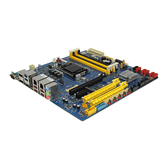
Page 13: Motherboard Layout
RX370Q User’s Manual Place this side towards the rear of the chassis. 1.2.3 Motherboard Layout... -
Page 14: Layout Content List
RX370Q User’s Manual 1.2.4 Layout Content List Item Description Item Description Front Audio Header Backlight Header Speaker Header Chassis Intrusion Header USB3.1 Gen1 Header (2x port) LVDS PWM Control Selection 5x RS232 Header Backlight Voltage Jumper 5x RS232 Voltage Selection Header... -
Page 15: Installing The Cpu
RX370Q User’s Manual resulting from incorrect installation/removal, misplacement/loss/incorrect removal of the PnP cap. ⚫ Install the CPU fan and heatsink assembly before you install motherboard to the chassis. If you purchased a separate CPU heatsink and fan assembly, make sure that you have properly applied Thermal Interface Material to the CPU heatsink or CPU before you install the heatsink and fan assembly. - Page 16 RX370Q User’s Manual 2. Press the load lever with your thumb (A), then move it to the left (B) until it is released from the retention tab. Retention tab Load lever To prevent damage to the socket pins, do not remove the PnP cap unless you are installing a CPU.
- Page 17 RX370Q User’s Manual 4. Position the CPU over the socket, making sure that the gold triangle is on the top-left corner of the socket then fit the socket alignment key into the CPU notch. CPU notch Gold triangle Alignment key 5.
-
Page 18: Installing The Cpu Heatsink And Fan
RX370Q User’s Manual 1.3.2 Installing the CPU Heatsink and Fan Intel® Core™ i7/ i5/ i3 LGA1151 processor requires a specially designed heatsink and fan assembly to ensure optimum thermal condition and performance. ⚫ Install the motherboard to the chassis before you install the CPU fan and heatsink assembly. - Page 19 RX370Q User’s Manual 2. Push down two fasteners at a time in a diagonal sequence to secure the heatsink and fan assembly in place. 3. Connect the CPU fan cable to the connector on the motherboard labeled J_CPU_FAN1. Do not forget to connect the fan cables to the fan connectors. Insufficient air flow inside the system may damage the motherboard components.
-
Page 20: Uninstalling The Cpu Heatsink And Fan
RX370Q User’s Manual 1.3.3 Uninstalling the CPU Heatsink and Fan To uninstall the CPU heatsink and fan: 1. Disconnect the CPU fan cable from the connector on the motherboard. 2. Rotate each fastener counterclockwise 3. Pull up two fasteners at a time in a diagonal sequence to disengage the heatsink and fan assembly from the motherboard. -
Page 21: System Memory
RX370Q User’s Manual 1.4 System Memory 1.4.1 Overview The motherboard comes with four 288-pin Double Data Rate 4 (DDR4) Dual Inline Memory Modules (DIMM) sockets. DDR4 SDRAM, an abbreviation for double data rate fourth generation synchronous dynamic random-access memory, is a type of synchronous dynamic random-access memory (SDRAM) with a high bandwidth ("double data rate") interface. -
Page 22: Installing A Dimm
RX370Q User’s Manual 1.4.2 Installing a DIMM Make sure to unplug the power supply before adding or removing DIMMs or other system components. Failure to do so may cause severe damage to both the motherboard and the components. 1. Locate the DIMM socket on the board. -
Page 23: Expansion Card
RX370Q User’s Manual 1.5 Expansion Card the future, you may need to install expansion cards. The following sub-sections describe the slots and the expansion cards that they support. Make sure to unplug the power cord before adding or removing expansion cards. -
Page 24: Pci Express Slot
RX370Q User’s Manual 1.5.3 PCI Express slot This motherboard supports 1x PCIe x16 slot that complies with the PCI Express specifications. 1x PCIe x1 slot 2x PCIe x16 slot (4 Lanes) 1.5.4 M.2 connector - M.2 A/E Key 2232 Slot (with USB &... -
Page 25: Jumpers
RX370Q User’s Manual 1.6 Jumpers 1.6.1 Clear CMOS (CLCMOS1) This jumper allows you to clear the Real Time Clock (RTC) RAM in CMOS. You can clear the CMOS memory of date, time, and system setup parameters by erasing the CMOS RTC RAM data. -
Page 26: At/Atx Power Mode Select (Jpson1)
RX370Q User’s Manual 1.6.2 AT/ATX Power Mode Select (JPSON1) This jumper allows you to select ATX Mode or AT mode 1.6.3 COM POWER SETTING (J27,J25,J33,J42,J40,J44) This jumper allows you to select COM1~6 to support Ring/+12V/+5V... -
Page 27: Com6 Termination Mode Selection (J45)
RX370Q User’s Manual 1.6.4 COM6 Termination Mode Selection (J45) (RS232) Jumpers (Optional): - Digi-Key reference part =>S9337-ND - 2Pin,2.54mm pitch 1.6.5 LVDS Blacklight PWM Voltage Selection (BKLVOL1) -
Page 28: Lvds Backlight Pwm Source Selection (Lvdsbkl1)
RX370Q User’s Manual 1.6.6 LVDS Backlight PWM Source Selection (LVDSBKL1) 1.6 Connectors DO NOT recommend mix matching GOLD plated connectors with TIN one. 1.7.1 Rear panel connectors Item Name Function Description COM6 Serial COM Port The Serial COM port 6 supports RS-232/422/485... - Page 29 RX370Q User’s Manual HDMI HDMI Port The HDMI port Connector DUSB_H USB 3.1 These two Universal Serial Bus (USB) ports are Gen1 port available for connecting USB 3.1 devices USBC_1 USB 3.1 This is USB 3.1 Gen2 Type-C connector Gen2 port LAN_DUS USB 3.1...
-
Page 30: Cpu And System Fan Connectors (J_Cpu_Fan1, J_Fio_Fan1, J_Rio_Fan1)
RX370Q User’s Manual 1.7.2 CPU and System fan connectors (J_CPU_FAN1, J_FIO_FAN1, J_RIO_FAN1) Connect the fan cables to the fan connectors on the motherboard, making sure that the black wire of each cable matches the ground pin of the connector. 1.7.3 Front Panel connector (J_FIO_1) This Connector is for a chassis-mounted front panel. -
Page 31: Atx Power Connectors (Atx24P_1 & Atx4P_1)
RX370Q User’s Manual ⚫ ATX Power Button/Soft-off Button (Pin 6-8) This 2-pin connector is for the system power button. Pressing the power button turns the system on or puts the system in sleep or soft-off mode depending on the BIOS settings. -
Page 32: Serial Port Connectors (Com1~5)
RX370Q User’s Manual 1.7.5 Serial Port Connectors (COM1~5) 1. DCD 2. RXD# 3. TXD# 4. DTR 5. GND 6. DSR 7. RST 8. CTS 9. RI 10. KEY 1.7.6 Serial ATA Connector (SATA1~6 ) SATA 1~6 support SATA 3.0. These connectors are for the Serial ATA signal cables for Serial ATA hard disk drives. -
Page 33: Usb Connectors (Fp_Usb2_1, Fp_Usb2_2, Fp_Usb2_3)
RX370Q User’s Manual 1.7.7 USB connectors (FP_USB2_1, FP_USB2_2, FP_USB2_3) These connectors are for USB 2.0 ports. Connect the optional USB module cable to any of these connectors, then install the module to a slot opening at the back of system chassis. -
Page 34: Lpt Port Connector (Lpt1)
RX370Q User’s Manual 1.7.9 LPT Port Connector (LPT1) 1. STROB# 2. AUTOFD# 3. PD0 4. FUALT# 5. PD1 6. INT# 7. PD2 8. SLCTIN# 9. PD3 10. GND 11. PD4 12. GND 13. PD5 14. GND 15. PD6 16. GND 17. -
Page 35: Lvds Backlight Connector (Jbkl1)
RX370Q User’s Manual 1.7.11 LVDS Backlight Connector (JBKL1) 1. +12V_BL 2. GND 3. BKLT_EN 4. BKLT_PWM 5. +5V_BL 1.7.12 Front Audio connector (J_HDA_1) 1. MIC2_L 2. AGND 3. MIC2_R 4. FP_HDADET 5. LINE2_R 6. MIC2_JD 7. FR-IO-SENSE 8. KEY 9. LINE2_L... -
Page 36: Amp Speaker Connector (Jamp1)
RX370Q User’s Manual 1.7.13 AMP speaker Connector (JAMP1) 4. Lout+ 3. Lout- 2. Rout+ 1. Rout- 1.7.14 LAN LED status connector (LAN_LED1) 1. LAN1 100 2. LAN2 100 3. NC 4. NC 5. LAN1 1G 6. LAN2 1G 7. LAN1 ACT 8. -
Page 37: Bits Gpio Connector (Gpio_Hdr1)
RX370Q User’s Manual 1.7.15 8 bits GPIO connector (GPIO_HDR1) 1. GPIO 1 2. GPIO 5 3. GPIO 2 4. GPIO 6 5. GPIO 3 6. GPIO 7 7. GPIO 4 8. GPIO 8 9. KEY 10. GND... -
Page 38: Chapter 2 - Bios Setup
RX370Q User’s Manual Chapter 2 - BIOS Setup 2.1 BIOS Menu Page Main Advanced Chipset Security Boot Save & Exit Item help BIOS Information BIOS Vender American Megatrends Core Version 5.13 Compliancy UEFI 2.7 ; PI 1.6 BIOS Version RX370Q (71601) V0.01... - Page 39 RX370Q User’s Manual Field Name Compliancy Default Value UEFI 2.7 ; PI 1.6 Comment This field is not selectable. There is no help text associated with it. Field Name BIOS Version Default Value Display the version of the BIOS Comment This field is not selectable.
-
Page 40: Advanced Page
RX370Q User’s Manual 2.2 Advanced Page Main Advanced Chipset Security Boot Save & Exit ►CPU Configuration Item help ►PCH-FW Configuration ►Trusted Computing ►ACPI Settings ►SMART Settings ►Super IO Configuration ►Hardware Monitor ►S5 RTC Wake Settings ►Intel TXT Information ►AMI Graphic Output Protocol Policy (Available when UEFI video) ►USB Configuration... - Page 41 RX370Q User’s Manual Field Name Super IO Configuration Help System Super IO Chip Parameters. Comment Press Enter when selected to go into the associated Sub-Menu. Field Name Hardware Monitor Help Monitor hardware status Comment Press Enter when selected to go into the associated Sub-Menu.
-
Page 42: Cpu Configuration
RX370Q User’s Manual 2.2.1 CPU Configuration Main Advanced Chipset Security Boot Save & Exit CPU Configuration Item help Type Intel(R) Core(TM) CPU i7-8700 CPU@ 3.20 GHz 0x906EA Speed 3200 MHz L1 Data Cache 32 KB x 6 L1 Instruction Cache... - Page 43 RX370Q User’s Manual Field Name L1 Instruction Cache Default Value L1 Instruction Cache Size Comment This field is not selectable. There is no help text associated with it. Field Name L2 Cache Default Value L2 Cache Size Comment This field is not selectable. There is no help text associated with it.
-
Page 44: Pch-Fw Configuration
RX370Q User’s Manual Field Name Intel Trusted Execution Technology Default Value [Disabled] Possible Value Enabled Disabled Help Enables utilization of additional hardware capabilities provided by Intel (R) Trusted Execution Technology. Changes require a full power cycle to take effect. 2.2.2 PCH-FW Configuration... -
Page 45: Amt Configuration
RX370Q User’s Manual Field Name ME Firmware Status 2 Default Value 0x80108106 Comment This field is not selectable. There is no help text associated with it. Field Name Manageability Features State Default Value [Enabled] Possible Value Enabled Disabled Help Enable/Disable Intel(R) Manageability features. NOTE:This option disables/enables Manageability Features support in FW. -
Page 46: Trusted Computing
RX370Q User’s Manual Field Name ASF support Default Value [Enabled] Possible Value Enabled Disabled Help Enable/Disable Alert Standard Format support. Field Name USB Provisioning of AMT Default Value [Disabled] Possible Value Enabled Disabled Help Enable/Disable of AMT USB Provisioning. 2.2.3 Trusted Computing... -
Page 47: Acpi Settings
RX370Q User’s Manual Field Name TPM2.0 UEFI Spec Version Default Value [TCG_2] Possible Value TCG_1_2 TCG_2 Help Select the TCG2 Spec Version Support,TCG_1_2: the Compatible mode for Win8/Win10,TCG_2: Support new TCG2 protocol and event format for Win10 or later. 2.2.4 ACPI Settings... -
Page 48: Smart Settings
RX370Q User’s Manual 2.2.5 SMART Settings Main Advanced Chipset Security Boot Save & Exit Item help SMART Settings SMART Self Test [Disabled] →←: Select Screen ↑↓: Select Item Enter: Select +/- : Change Opt F1: General Help F2: Previous Values F3: Optimized Defaults F4: Save &... - Page 49 RX370Q User’s Manual Field Name Serial Port 1 Configuration Help Set Parameters of Serial Port 1 (COMA) Comment Press Enter when selected to go into the associated Sub-Menu. Field Name Serial Port 2 Configuration Help Set Parameters of Serial Port 2 (COMB) Comment Press Enter when selected to go into the associated Sub-Menu.
-
Page 50: Serial Port 1 Configuration
RX370Q User’s Manual 2.2.6.1 Serial Port 1 Configuration Main Advanced Chipset Security Boot Save & Exit Serial Port 1 Configuration Item help Serial Port [Enabled] →←: Select Screen Device Settings IO=2E8h; IRQ=7; ↑↓: Select Item Enter: Select Change Settings [Auto]... -
Page 51: Serial Port 2 Configuration
RX370Q User’s Manual 2.2.6.2 Serial Port 2 Configuration Main Advanced Chipset Security Boot Save & Exit Serial Port 2 Configuration Item help Serial Port [Enabled] →←: Select Screen Device Settings IO=2F0h; IRQ=7; ↑↓: Select Item Enter: Select Change Settings [Auto]... -
Page 52: Serial Port 3 Configuration
RX370Q User’s Manual 2.2.6.3 Serial Port 3 Configuration Main Advanced Chipset Security Boot Save & Exit Serial Port 3 Configuration Item help Serial Port [Enabled] →←: Select Screen Device Settings IO=3E8h; IRQ=7; ↑↓: Select Item Enter: Select Change Settings [Auto]... -
Page 53: Serial Port 4 Configuration
RX370Q User’s Manual 2.2.6.4 Serial Port 4 Configuration Main Advanced Chipset Security Boot Save & Exit Serial Port 4 Configuration Item help Serial Port [Enabled] →←: Select Screen Device Settings IO=3F8h; IRQ=4; ↑↓: Select Item Enter: Select Change Settings [Auto]... -
Page 54: Serial Port 5 Configuration
RX370Q User’s Manual 2.2.6.5 Serial Port 5 Configuration Main Advanced Chipset Security Boot Save & Exit Serial Port 5 Configuration Item help Serial Port [Enabled] →←: Select Screen Device Settings IO=2F8h; IRQ=3; ↑↓: Select Item Enter: Select Change Settings [Auto]... -
Page 55: Serial Port 6 Configuration
RX370Q User’s Manual 2.2.6.6 Serial Port 6 Configuration Main Advanced Chipset Security Boot Save & Exit Serial Port 6 Configuration Item help Serial Port [Enabled] →←: Select Screen Device Settings IO=2E0h; IRQ=7; ↑↓: Select Item Enter: Select Change Settings [Auto]... -
Page 56: Parallel Port Configuration
RX370Q User’s Manual 2.2.6.7 Parallel Port Configuration Main Advanced Chipset Security Boot Save & Exit Parallel Port Configuration Item help Parallel Port [Enabled] →←: Select Screen Device Settings IO=378h; IRQ=5; ↑↓: Select Item Enter: Select Change Settings [Auto] +/- : Change Opt... -
Page 57: Hardware Monitor
RX370Q User’s Manual 2.2.7 Hardware Monitor Main Advanced Chipset Security Boot Save & Exit PC Health Status Item help CPU Temperature : xx °C →←: Select Screen CPU VR Temperature : xx °C ↑↓: Select Item DIMM Temperature : xx °C... -
Page 58: Smart Fan
RX370Q User’s Manual 2.2.7.1 Smart Fan Main Advanced Chipset Security Boot Save & Exit Smart Fan Item help Smart Fan Function [Disabled] →←: Select Screen ►Smart Fan Mode Configuration ↑↓: Select Item Enter: Select +/- : Change Opt F1: General Help... -
Page 59: Smart Fan Mode Configuration
RX370Q User’s Manual 2.2.7.1.1 Smart Fan Mode Configuration Main Advanced Chipset Security Boot Save & Exit Item help CPU Fan Setting Temperature 1 Temperature 2 Temperature 3 Temperature 4 FD/RPM 1 FD/RPM 2 FD/RPM 3 FD/RPM 4 Front Fan Setting... - Page 60 RX370Q User’s Manual Field Name Temperature 1 Default Value By thermal fan profile. Possible Value By temperature. Help The value of temperature 1 Field Name Temperature 2 Default Value By thermal fan profile. Possible Value By temperature. Help The value of temperature 2...
-
Page 61: S5 Rtc Wake Settings
RX370Q User’s Manual 2.2.8 S5 RTC Wake Settings Main Advanced Chipset Security Boot Save & Exit Wake system from S5 [Disabled] Item help Wake up hour Wake up minute Wake up second →←: Select Screen ↑↓: Select Item Enter: Select... -
Page 62: Intel Txt Information
RX370Q User’s Manual 2.2.9 Intel TXT Information Main Advanced Chipset Security Boot Save & Exit Intel TXT Information Item help Chipset Production Fused →←: Select Screen BiosAcm Production Fused ↑↓: Select Item Chipset Txt Supported Enter: Select CPU Txt Supported... - Page 63 RX370Q User’s Manual Field Name Output Select Default Value By attached device. Possible Value eDP(LVDS Control enabled) / DP1 / DP2 / HDMI3 Help Output Interface Field Name LCD Panel Type Default Value [1920x1080 24bit Dual Channel] Possible Value 800x600 18bit Single Channel...
-
Page 64: Usb Configuration
RX370Q User’s Manual 2.2.11 USB Configuration Main Advanced Chipset Security Boot Save & Exit USB Configuration Item help USB Module Version USB Controllers: 1 XHCI USB Devices: 1 Keyboard, 1Mouse, 2 Hubs Legacy USB Support [Enabled] →←: Select Screen XHCI Hand-off [Enabled] ↑↓: Select Item... -
Page 65: Network Stack Configuration
RX370Q User’s Manual 5 sec 10 sec 20 sec Help The time-out value for Control, Bulk, and Interrupt transfers. Field Name Device reset time-out Default Value [20 sec] Possible Value 10 sec 20 sec 30 sec 40 sec Help USB mass storage device Start Unit command time-out. -
Page 66: Csm Configuration
RX370Q User’s Manual be available. Field Name Ipv6 PXE Support (Available when Network stack Enabled) Default Value [Enabled] Possible Value Disabled Enabled Help Enable/Disable Ipv6 PXE Boot Support. If disabled IPV6 PXE boot support will not be available. 2.2.13 CSM Configuration... -
Page 67: Nvme Configuration
RX370Q User’s Manual Field Name Video (Available when CSM Support Enabled) Default Value [UEFI] Possible Value Do not launch UEFI Legacy Help Controls the execution of UEFI and Legacy Video OpROM Field Name Other PCI devices (Available when CSM Support Enabled) -
Page 68: Intel (R) Rapid Storage Technology
RX370Q User’s Manual 2.2.15 Intel (R) Rapid Storage Technology Available configure the RST as down below and after system reboot. Chipet->PCH-IO-Configuration ->SATA amd RSTT configuration -> SATA Mode Selection -> Intel RST Premium With Intel Optane System Acceleration (selected) Main... -
Page 69: Chipset Page
RX370Q User’s Manual 2.3 Chipset Page Main Advanced Chipset Security Boot Save & Exit ►System Agent (SA) Configuration Item help ►PCH-IO Configuration →←: Select Screen ↑↓: Select Item Enter: Select +/- : Change Opt F1: General Help F2: Previous Values F3: Optimized Defaults F4: Save &... -
Page 70: System Agent (Sa) Configuration
RX370Q User’s Manual 2.3.1 System Agent (SA) Configuration Main Advanced Chipset Security Boot Save & Exit System Agent (SA) Configuration Item help ►Memory Configuration ►Graphics Configuration ►PEG Port Configuration →←: Select Screen VT-d [Enabled] ↑↓: Select Item Enter: Select +/- : Change Opt... -
Page 71: Memory Configuration
RX370Q User’s Manual 2.3.1.1 Memory Configuration Main Advanced Chipset Boot Security Save & Exit Memory Configuration Item help Memory RC Version 0.7.1.72 →←: Select Screen Memory Frequency 2667 Mhz ↑↓: Select Item Memory Timings (tCL-tRCD-tRP-tRAS) 19-19-19-43 Enter: Select DIMM#1 16384 MB (DDR4) -
Page 72: Graphics Configuration
RX370Q User’s Manual 2.3.1.2 Graphics Configuration Main Advanced Chipset Security Boot Save & Exit Graphics Configuration Item help Primary Display [Auto] →←: Select Screen Internal Graphics [Auto] ↑↓: Select Item Enter: Select PSMI SUPPORT [Disabled] +/- : Change Opt DVMT Pre-Allocated... -
Page 73: Lcd Control
RX370Q User’s Manual 2.3.1.2.1 LCD Control Main Advanced Chipset Security Boot Save & Exit LCD Control Item help Primary IGFX Boot Display [VBIOS Default] →←: Select Screen Secondary IGFX Boot Display [Disabled] ↑↓: Select Item Enter: Select LCD Panel Type... -
Page 74: Peg Port Configuration
RX370Q User’s Manual setup item. Field Name Backlight Control Default Value [PWM Normal] Possible Value PWM Inverted PWM Normal Help Back Light Control Setting Field Name LVDS Control Default Value [Disabled] Possible Value Disabled Enabled Help Enabled/Disabled the LVDS. Field Name... -
Page 75: Pch-Io Configuration
RX370Q User’s Manual Possible Value Auto / Force X1 / Force X2 / Force X4 / Force X8 Help Force PEG link to retrain to X1/2/4/8 Field Name ASPM (Suppress if no card detected) Default Value [Auto] Possible Value Disabled / Auto / ASPM L0s / ASPM L1 / ASPM L0sL1 Help Control ASPM support for the PEG 0. - Page 76 RX370Q User’s Manual Field Name USB Configuration Help USB Configuration settings Comment Press Enter when selected to go into the associated Sub-Menu. Field Name HD Audio Configuration Help HD Audio Subsystem Configuration Settings Comment Press Enter when selected to go into the associated Sub-Menu.
-
Page 77: Pci Express Configuration
RX370Q User’s Manual Default Value [Disabled] Possible Value Enabled / Disabled / Reset Help Configure Chassis Intrusion 2.3.2.1 PCI Express Configuration Main Advanced Chipset Boot Security Save & Exit PCI Express Configuration Item help ►PCI Express X4 Slot3 ►PCI Express M.2 E →←: Select Screen... -
Page 78: Pci Express X4 Slot3
RX370Q User’s Manual 2.3.2.1.1 PCI Express X4 Slot3 Main Advanced Chipset Boot Security Save & Exit Item help PCI Express X4 Slot3 [Enabled] Topology [Board specific] →←: Select Screen ASPM [Auto] ↑↓: Select Item L1 Substates [L1.1 & L1.2] Enter: Select... -
Page 79: Pci Express M.2 E
RX370Q User’s Manual 2.3.2.1.2 PCI Express M.2 E Main Advanced Chipset Boot Security Save & Exit Item help PCI Express M.2 E [Enabled] Topology [Board specific] →←: Select Screen ASPM [Auto] ↑↓: Select Item L1 Substates [L1.1 & L1.2] Enter: Select... -
Page 80: Pci Express M.2 M
RX370Q User’s Manual 2.3.2.1.3 PCI Express M.2 M Main Advanced Chipset Boot Security Save & Exit Item help PCI Express M.2 M [Enabled] Topology [Board specific] →←: Select Screen ASPM [Auto] ↑↓: Select Item L1 Substates [L1.1 & L1.2] Enter: Select... -
Page 81: Pci Express X1 Slot2
RX370Q User’s Manual 2.3.2.1.4 PCI Express X1 Slot2 Main Advanced Chipset Boot Security Save & Exit Item help PCI Express X1 Slot2 [Enabled] Topology [Board specific] →←: Select Screen ASPM [Auto] ↑↓: Select Item L1 Substates [L1.1 & L1.2] Enter: Select... -
Page 82: Pci Express X4 Slot4
RX370Q User’s Manual 2.3.2.1.5 PCI Express X4 Slot4 Main Advanced Chipset Boot Security Save & Exit Item help PCI Express X4 Slot4 [Enabled] Topology [Board specific] →←: Select Screen ASPM [Auto] ↑↓: Select Item L1 Substates [L1.1 & L1.2] Enter: Select... -
Page 83: Sata And Rst Configuration
RX370Q User’s Manual 2.3.2.2 SATA And RST Configuration Main Advanced Chipset Boot Security Save & Exit SATA And RST Configuration Item help SATA Mode Selection [AHCI] PCIe Storage Dev On Port 9 [Not RST Controlled] →←: Select Screen ↑↓: Select Item... -
Page 84: Usb Configuration
RX370Q User’s Manual Value Display the installed SATA port device. Comment This field is not selectable. There is no help text associated with it. 2.3.2.3 USB Configuration Main Advanced Chipset Boot Security Save & Exit USB Configuration Item help XHCI Compliance Mode... -
Page 85: Hd Audio Configuration
RX370Q User’s Manual Value [Enabled] Possible Value Disabled / Enabled Help Enable/Disable USB ports of USB2 Header 1. Field Name Front IO USB2 Header 2 Power Value [Enabled] Possible Value Disabled / Enabled Help Enable/Disable USB ports of USB2 Header 2. -
Page 86: Security Page
RX370Q User’s Manual 2.4 Security Page Main Advanced Chipset Security Boot Save & Exit Password Description Item help If Only the Administrator's password is set, then this only limits access to Setup and is only asked for when entering Setup. -
Page 87: Hdd Security
RX370Q User’s Manual Field Name ME Update Value [Disabled] Possible Value Disabled / Enabled Help Flash Security Override. Field Name Secure Boot Help Secure Boot Configuration Comment Press Enter when selected to go into the associated Sub-Menu. Field Name Secure Flash Update... -
Page 88: Secure Boot
RX370Q User’s Manual 2.4.2 Secure Boot Main Advanced Chipset Security Boot Save & Exit System Mode Setup Item help Secure Boot [Disabled] →←: Select Screen Not Active ↑↓: Select Item Enter: Select Secure Boot Mode [Custom] +/- : Change Opt F1: General Help ►... -
Page 89: Key Management
RX370Q User’s Manual 2.4.2.1 Key Management Main Advanced Chipset Security Boot Save & Exit Vender Key Valid Item help Factory Key Provision [Disabled] ► Restore Factory Keys ► Reset To Setup Mode ► Export Secure Boot variables ► Enroll Efi Image ►... - Page 90 RX370Q User’s Manual Field Name Enroll Efi Image Help Allow the image to run in Secure Boot mode. Enroll SHA256 Hash certificate of a PE image into Authorized Signature Database (db) Field Name Remove ‘UEFI CA’ from DB Help Device Guard ready system must not list 'Microsoft UEFI CA' Certificate in...
- Page 91 RX370Q User’s Manual Field Name Forbidden Signatures Default Value Size:0, Keys:0, Key source: No Keys Help Enroll Factory Defaults or load certificates from a file: 1.Public Key Certificate: a)EFI_SIGNATURE_LIST b)EFI_CERT_X509 (DER) c)EFI_CERT_RSA2048 (bin) d)EFI_CERT_SHAXXX 2.Authenticated UEFI Variable 3.EFI PE/COFF Image(SHA256)
-
Page 92: Secure Flash Update
RX370Q User’s Manual 2.4.3 Secure Flash Update Built-In BIOS flash tool. To store RX370Q ROM file into the USB drive and select the ROM file path along with the “Path for ROM image”.The system will reboot to the “Flash BIOS” page. -
Page 93: Boot Page
RX370Q User’s Manual 2.5 Boot Page Main Advanced Chipset Security Boot Save & Exit Boot Configuration Item help Setup Prompt Timeout Bootup NumLock State [On] Boot mode select [UEFI] FIXED BOOT ORDER Priorities Boot Option #1 [USB Floppy] Boot Option #2... - Page 94 RX370Q User’s Manual Field Name Boot mode select Default Value [UEFI] Possible Value LEGACY UEFI Help BIOS boot mode. Windows 10 select [UEFI] DOS select [Legacy] Field Name Boot Option #1 Default Value [USB Floppy] Possible Value USB Floppy, CD/DVD, USB CD/DVD, Hard Disk , USB Key, USB Hard Disk ,...
- Page 95 RX370Q User’s Manual Field Name Boot Option #8 (UEFI Only) Default Value [UEFI AP:EFI:Built-in EFI Shell] Possible Value USB Floppy, CD/DVD, USB CD/DVD, Hard Disk , USB Key, USB Hard Disk , Network, Disabled, (UEFI Only)UEFI AP:UEFI: Build-in EFI Shell...
-
Page 96: Save & Exit Page
RX370Q User’s Manual 2.6 Save & Exit Page Main Advanced Chipset Security Boot Save & Exit Save Options Item help Discard Changes and Exit Save Changes and Reset Discard Changes and Reset Restore Defaults →←: Select Screen ↑↓: Select Item... -
Page 97: Drivers Installing Note
RX370Q User’s Manual Drivers Installing Note Microsoft Windows update. DO the Microsoft Windows update before to install BCM drivers for RX370Q or you might experience failure on some drivers installation . How to do that. You could through the LAN2 port for the Microsoft Windows update .
Need help?
Do you have a question about the RX370Q and is the answer not in the manual?
Questions and answers