
Related Manuals for BCM RX680R


Summary of Contents for BCM RX680R
- Page 1 RX680R Intel® R680E support 12 generation Core™ i9, Core i7, Core i5, Core i3, Pentium, Celeron Micro-ATX Motherboard User’s Manual V1.1...
-
Page 2: Table Of Contents
About this guide ......................7 Typography ......................... 8 Packing List ........................ 9 Revision History ....................... 10 RX680R Motherboard Features ................11 Specifications Summary ..................11 Block Diagram ......................13 Chapter 1 - Product Introduction ................14 1.1 Before you Proceed ......................15 1.2 Motherboard Overview .................... - Page 3 RX680R User’s Manual 1.7.3 System Panel (FIO_PANEL) ........................34 1.7.4 ATX power connectors (ATX24P_1& ATX12V) ..................35 1.7.5 Serial Port connectors (COM1~6) ......................36 1.7.6 Serial ATA connector (SATA1~4 ) ......................36 1.7.7 USB connectors (USB2_HR1, USB2_HR2, USB2_HR3, USB2_HR4) ..........37 1.7.8 USB3.2 connector (USB3_HR1) ......................
- Page 4 RX680R User’s Manual 2.2.11 NVMe Configuration ..........................71 2.3 Chipset ..........................72 2.3.1 System Agent (SA) Configuration ......................73 2.3.1.1 Memory Configuration ............................ 74 2.3.1.2 Graphic Configuration ............................. 75 2.3.1.3 VMD setup menu ............................76 2.3.2 PCH-IO Configuration ..........................76 2.3.2.1 PCI Express Configuration ..........................
-
Page 5: Safety Information
RX680R User’s Manual Safety Information Electrical safety To prevent electrical shock hazard, disconnect the power cable from the electrical outlet ⚫ before relocating the system. When adding or removing devices to or from the system, ensure that the power cables ⚫... - Page 6 RX680R User’s Manual Safety Declaration This device complies with the requirements in Part 15 of the FCC rules. Operation is subject to the following two conditions: This device may not cause harmful interference. ⚫ This device must accept any interference received, including interference that may ⚫...
-
Page 7: About This Guide
Where to find more information Refer to the following sources for additional information and for product and software updates. 1. Motherboard User’s Manual and Device Drivers Motherboard User’s Manual and Device Drivers can be downloaded at BCM Advanced Research website: https://www.bcmcom.com/product_industrialMB_MATX.html 2. Technical Support If a problem arises with your system and no solution can be obtained from the user’s manual,... -
Page 8: Typography
RX680R User’s Manual Typography Bold text Indicates a menu or an item to select Italics Used to emphasize a word or a phrase <Key> Keys enclosed in the less-than and greater-than sign means that you must press the enclosed key Example: <Enter>... -
Page 9: Packing List
RX680R User’s Manual Packing List Before you begin installing your single board, please make sure that the following materials have been shipped: 1 x RX680R Micro-ATX Main board ⚫ 1 x I/O Shield ⚫ If any of the above items is damaged or missing, please contact your... -
Page 10: Revision History
RX680R User’s Manual Revision History Revision Revision History Date V 1.0 First release version Oct, 2022 V 1.1 Nov, 2022 Add BIOS Programming command. Change Line out port to Green color. -
Page 11: Rx680R Motherboard Features
RX680R User’s Manual RX680R Motherboard Features This chapter briefly describes the features of Board RX680R. The Table summarizes the major features of this board as below: Specifications Summary Specifications System Intel® Alder Lake Processor Up to 16 Cores 24 Threads Hybrid, TDP Max 125W. - Page 12 RX680R User’s Manual 1 x 2 Audio Connector, Green color for line-out, Pink color for Mic-In Internal I/O Connector 4 x SATA III Vertical Connectors (Red) 5 x RS-232 Headers with Voltage Selection Internal I/O 1 x RS-232/422/485 Headers with Voltage Selection...
-
Page 13: Block Diagram
RX680R User’s Manual Block Diagram... -
Page 14: Chapter 1 - Product Introduction
RX680R User’s Manual This chapter describes the motherboard features and the new technologies it supports. Product Introduction... -
Page 15: Before You Proceed
RX680R User’s Manual 1.1 Before you Proceed Take note of the following precautions before you install motherboard components or change any motherboard settings. Unplug the power cord from the wall socket before touching any ⚫ component. Use a grounded wrist strap or touch a safely grounded object or ⚫... -
Page 16: Screw Holes
RX680R User’s Manual 1.2.2 Screw Holes Place eight (8) screws into the holes indicated by circles to secure the motherboard to the chassis. Do not over tighten the screws! Doing so can damage the motherboard. Place this side towards the rear of the chassis... -
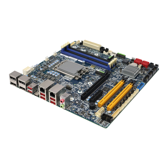
Page 17: Motherboard Layout
RX680R User’s Manual 1.2.3 Motherboard Layout... -
Page 18: Layout Content List
RX680R User’s Manual 1.2.4 Layout Content List Slots & Sockets Print Name Function Note CPU1 LGA 1700 Socket J50~J53 DDR5 UDIMM Slots Dual channel (2DPC) PCIE_X16_SLOT1 Gen 5 PCIe x16 Physical Black (Slot1) PCIE_X4_SLOT2 Gen 3 PCIe x4 Open Ended (Slot 2) - Page 19 RX680R User’s Manual Internal I/O Connectors Print Name Function Note CPU_FAN1 CPU FAN Connector WAFER 1x4, 2.54mm SYS_FAN1 Chassis Fan Connector WAFER 1x4, 2.54mm SYS_FAN2 Chassis Fan Connector WAFER 1x4, 2.54mm FIO_PANEL1 Front Panel Connector BOX header 2x5P, 2.54mm ATX24P_1...
-
Page 20: Central Processing Unit (Cpu)
PnP cap is missing, or if you see any damage to the PnP cap/socket pins/motherboard components. BCM will shoulder the cost of repair only if the damage is shipment/transit-related. Keep the cap after installing the motherboard. BCM will process ⚫... -
Page 21: Installing The Cpu
RX680R User’s Manual 1.3.1 Installing the CPU 1. Locate the CPU socket on the motherboard. Before installing the CPU, make sure that the socket box is facing towards you and the load lever is on your left. 2. Press the load lever with your thumb (A), then move it to the left (B) until it is released from the retention tab. - Page 22 RX680R User’s Manual 4. Position the CPU over the socket, making sure that the gold triangle is on the top-left corner of the socket then fit the socket alignment key into the CPU notch. Socket and processor Pin 1 indicators...
-
Page 23: Installing The Cpu Heatsink And Fan
RX680R User’s Manual 1.3.2 Installing the CPU Heatsink and Fan Intel® Core™ i9/ i7/ i5/ i3 LGA1700 processor requires a specially designed heatsink and fan assembly to ensure optimum thermal condition and performance. ⚫ Install the motherboard to the chassis before you install the CPU fan and heatsink assembly. - Page 24 RX680R User’s Manual 2. Push down or fasten two fasteners at a time in a diagonal sequence to secure the heatsink and fan assembly in place. 3. Connect the CPU fan cable to the connector on the motherboard labeled CPU_FAN.
-
Page 25: Uninstalling The Cpu Heatsink And Fan
RX680R User’s Manual 1.3.3 Uninstalling the CPU Heatsink and Fan To uninstall the CPU heatsink and fan: 1. Disconnect the CPU fan cable from the connector on the motherboard. 2. Rotate each fastener counterclockwise. 3. Pull up or unfasten two fasteners at a time in a diagonal sequence to disengage the heatsink and fan assembly from the motherboard. -
Page 26: System Memory
The DDR5 specification is bringing the maximum potential capacity for a single DDR5 DIMM to 128GB, a theoretical maximum transfer speed of 4800MHz which is doubling the rate of DDR4, along with the improved power consumption as 1.1V. and RX680R is two DIMMs per Channel designed which the speed is up to 4400MHz. -
Page 27: Installing A Dimm
RX680R User’s Manual 1.4.2 Installing a DIMM Make sure to unplug the power supply before adding or removing DIMMs or other system components. Failure to do so may cause severe damage to both the motherboard and the components. 1. Locate the DIMM socket on the board. -
Page 28: Installing An Expansion Card
RX680R User’s Manual 1.5.1 Installing an Expansion Card 1. Before installing the expansion card, read the documentation that came with it and make the necessary hardware settings for the card. 2. Remove the system unit cover (if your motherboard is already installed in a chassis). -
Page 29: Pci Express X4 Slot
RX680R User’s Manual 1.5.4 PCI Express x4 slot This motherboard supports one PCIe x4 slot that complies with the PCIe x4 specifications. PCIE_X4_Slot2: Gen 3 PCIe x4 Open Ended 1.5.5 M.2 connectors Support PCIe, SATA and USB interface of this connector. -
Page 30: Jumpers
RX680R User’s Manual 1.6 Jumpers 1.6.1 Clear CMOS (CMOS1) This jumper allows you to clear the Real Time Clock (RTC) RAM in CMOS. You can clear the CMOS memory of date, time, and system setup parameters by erasing the CMOS RTC RAM data. -
Page 31: At/Atx Power Mode Select (At1)
RX680R User’s Manual 1.6.2 AT/ATX Power Mode Select (AT1) This jumper allows you to select ATX Mode or AT mode. 1.6.3 COM POWER SETTING (J56,J45~J48,J25) This jumper allows you to select COM1~6’s power to support Ring/+12V/+5V. -
Page 32: Lvds Panel Power Select (Panel_Sel1)
RX680R User’s Manual 1.6.4 LVDS Panel Power Select (PANEL_SEL1) This jumper allows you to select the LVDS Panel’s power. 1.6.5 LVDS Blacklight Voltage Selection (BKLVOL1) This jumper allows you to select the LVDS’s Blacklight power. -
Page 33: Connectors
RX680R User’s Manual 1.7 Connectors 1.7.1 Rear panel connectors Item Name Function Description Display Port These four display port connectors are available for connecting display port devices. USB3.2 USB 3.2 Type C This is USB 3.2 Type-C connector USB3.2 USB 3.2 Type A These six Universal Serial Bus (USB) ports are available for connecting USB 3.2 devices. -
Page 34: Cpu And System Fan Connectors (Cpu_Fan1, Sys_Fan1, Sys_Fan2)
RX680R User’s Manual 1.7.2 CPU and System fan connectors ( CPU_FAN1, SYS_FAN1, SYS_FAN2 ) Connect the fan cables to the fan connectors on the motherboard, making sure that the black wire of each cable matches the ground pin of the connector. -
Page 35: Atx Power Connectors (Atx24P_1& Atx12V)
RX680R User’s Manual ATX Power Button/Soft-off Button (Pin 6-8) ⚫ This 2-pin connector is for the system power button. Pressing the power button turns the system on or puts the system in sleep or soft-off mode depending on the BIOS settings. -
Page 36: Serial Port Connectors (Com1~6)
RX680R User’s Manual 1.7.5 Serial Port connectors (COM1~6) This connector is for a serial (COM) port. Connect the serial port module cable to this connector, then install the module to a slot opening at the back of the system chassis. -
Page 37: Usb Connectors (Usb2_Hr1, Usb2_Hr2, Usb2_Hr3, Usb2_Hr4)
RX680R User’s Manual 1.7.7 USB connectors (USB2_HR1, USB2_HR2, USB2_HR3, USB2_HR4) These connectors are for USB 2.0 ports. Connect the optional USB module cable to any of these connectors, then install the module to a slot opening at the back of the system chassis. -
Page 38: Front Audio Connector (Fio_Aud1)
RX680R User’s Manual 1.7.9 Front Audio connector (FIO_AUD1) This connector is for a chassis-mounted front panel audio I/O module that supports either HD Audio or legacy AC ‘97 (optional) audio standard. 1. MIC2_L 2. AGND 3. MIC2_R 4. FP_HDADET 5. LINE2_R 6. -
Page 39: Lvds Connector (Lvds1)
RX680R User’s Manual 1.7.11 LVDS connector (LVDS1) The PANEL_PWR which select from PANEL_SEL1 jumper and default (+5V). 1. +3V 2. +5V (PANEL_PWR) 3. +3V 4. +5V (PANEL_PWR) 5. LS_SCL 6. LS_SDA 7. CABLE_ID1 8.GND 9. LS0_L1_D+ 10. LS0_L0_D+ 11. LS0_L1_D- 12. -
Page 40: Lan Led Status Connector (Lan_Led1)
RX680R User’s Manual 1.7.13 LAN LED status connector (LAN_LED1) 1. 1G_LAN1_LED 2. 1G_LAN2_LED 3. GND 4. GND 5. 2.5G_LAN1_LED 6. 2.5G_LAN2_LED 7. GND 8. GND 9. LAN1_ACT 10. LAN2_ACT 1.7.14 Chassis intrusion connector (INTRUD1) This connector allow user to connect a sensor in system case. Once the chassis is opened, system will alert user or administrator. -
Page 41: Bit Gpio Header (Gpio_Hdr1)
RX680R User’s Manual 1.7.15 8 bit GPIO header (GPIO_HDR1) This connector provides a 8 bits input or output for general purpose. 1. AP_GPIO1 2. AP_GPIO5 3. AP_GPIO2 4. AP_GPIO6 5. AP_GPIO3 6. AP_GPIO7 7. AP_GPIO4 8. AP_GPIO8 9. SMB_CLK 10. SMB_DATA 11. -
Page 42: Chapter 2 - Bios Setup
RX680R User’s Manual This chapter tells how to change the system settings through the BIOS Setup menus. Detailed descriptions of the BIOS parameters are also provided. BIOS Setup... -
Page 43: Main Page
RX680R User’s Manual 2.1 Main Page Main Advanced Chipset Security Boot Save & Exit MEBx Item help BIOS Information BIOS Vendor American Megatrends Core Version 5.25 Compliancy UEFI 2.8 ; PI 1.7 BIOS Version RX680R (71881) BIOS V0.01 Build Date... -
Page 44: Advanced Bios Setup
RX680R User’s Manual Total Memory Field Name Value Display the installed memory size. Comment This field is not selectable. There is no help text associated with it. Field Name Memory Data Rate Value Display the installed memory frequency. Comment This field is not selectable. There is no help text associated with it. - Page 45 RX680R User’s Manual Field Name CPU Configuration Help CPU Configuration Parameters. Comment Press Enter when selected to go into the associated Sub-Menu. Field Name PCH-FW Configuration Help Configure Management Engine Technology Parameters. Comment Press Enter when selected to go into the associated Sub-Menu.
-
Page 46: Cpu Configuration
RX680R User’s Manual 2.2.1 CPU Configuration Main Advanced Chipset Security Boot Save & Exit MEBx Item help CPU Configuration ►Efficient-core Information ►Performance-core Information 0x90675 Brand String Gen Intel® Core ™ i3-12100TE Supported SMX/TXT Not Supported TXT Crash Code 0x00000000 TXT SPAD... - Page 47 RX680R User’s Manual Field Name Default Value VMX Supported or Not Comment This field is not selectable. There is no help text associated with it. SMX/TXT Field Name Default Value SMX/TXT Supported or Not Comment This field is not selectable. There is no help text associated with it.
-
Page 48: Performance-Core Information
RX680R User’s Manual 2.2.1.1 Performance-core Information Main Advanced Chipset Security Boot Save & Exit MEBx Item help Performance-core Information Frequency 3000 MHz L1 Data Cache 48 KB x 6 L1 Instruction Cache 32 KB x 6 L2 Cache 1280 KB x 6... -
Page 49: Pch-Fw Configuration
RX680R User’s Manual 2.2.2 PCH-FW Configuration Main Advanced Chipset Security Boot Save & Exit MEBx Item help ME Firmware Version 16.0.15.1620 ME Firmware Mode Normal Mode ME Firmware SKU Corporate SKU ME Firmware Status 1 0x90000255 ME Firmware Status 2... -
Page 50: Tpm Configuration
RX680R User’s Manual Field Name ME Firmware Status 4 Default Value 0x00004000 Comment This field is not selectable. There is no help text associated with it. Field Name ME Firmware Status 5 Default Value 0x00000000 Comment This field is not selectable. There is no help text associated with it. -
Page 51: Trusted Computing
RX680R User’s Manual Field Name TPM Device Selection Default Value [dTPM] Possible Value dTPM Help Selects TPM device: PTT or dTPM. PTT – Enables PTT in SkuMgr dTPM 1.2 – Disables PTT in SkuMgr Warning ! PTT/dTPM will be disabled and all data saved on it will be lost 2.2.3 Trusted Computing... -
Page 52: Acpi Settings
RX680R User’s Manual 2.2.4 ACPI Settings Main Advanced Chipset Security Boot Save & Exit MEBx Item help Enable ACPI Auto Configuration [Disabled] Enable Hibernation [Enabled] ↑↓: Select Item ACPI Sleep State [S3 (Suspend to RAM)] +/- : Change Opt F1: General Help... -
Page 53: Nct6126D Super Io Configuration
RX680R User’s Manual 2.2.5 NCT6126D Super IO Configuration Main Advanced Chipset Security Boot Save & Exit MEBx NCT6126D Super IO Configuration Item help Super IO Chip NCT6126D ►Serial Port 1 Configuration →←: Select Screen ►Serial Port 2 Configuration ↑↓: Select Item ►Serial Port 3 Configuration... -
Page 54: Serial Port 1 Configuration
RX680R User’s Manual WatchDog Count Mode Field Name Default Value [Second] Possible Value Second Minute Help Configure watchdog count mode. Field Name WatchDog Timeout Value Default Value Possible Value 0~255 Help Configure watchdog Timeout Value. 2.2.5.1 Serial Port 1 Configuration... -
Page 55: Serial Port 2 Configuration
RX680R User’s Manual 2.2.5.2 Serial Port 2 Configuration Main Advanced Chipset Security Boot Save & Exit MEBx Serial Port 2 Configuration Item help →←: Select Screen Serial Port [Enabled] ↑↓: Select Item Device Settings IO=2F8h; IRQ=3; Enter: Select +/- : Change Opt... -
Page 56: Serial Port 3 Configuration
RX680R User’s Manual 2.2.5.3 Serial Port 3 Configuration Main Advanced Chipset Security Boot Save & Exit MEBx Serial Port 3 Configuration Item help →←: Select Screen Serial Port [Enabled] ↑↓: Select Item Device Settings IO=3E8h; IRQ=7; Enter: Select +/- : Change Opt... -
Page 57: Serial Port 4 Configuration
RX680R User’s Manual 2.2.5.4 Serial Port 4 Configuration Main Advanced Chipset Security Boot Save & Exit MEBx Serial Port 4 Configuration Item help →←: Select Screen Serial Port [Enabled] ↑↓: Select Item Device Settings IO=2E8h; IRQ=7; Enter: Select +/- : Change Opt... -
Page 58: Serial Port 5 Configuration
RX680R User’s Manual 2.2.5.5 Serial Port 5 Configuration Main Advanced Chipset Security Boot Save & Exit MEBx Serial Port 5 Configuration Item help →←: Select Screen Serial Port [Enabled] ↑↓: Select Item Device Settings IO=220h; IRQ=7; Enter: Select +/- : Change Opt... -
Page 59: Serial Port 6 Configuration
RX680R User’s Manual 2.2.5.6 Serial Port 6 Configuration Main Advanced Chipset Security Boot Save & Exit MEBx Serial Port 6 Configuration Item help →←: Select Screen Serial Port [Enabled] ↑↓: Select Item Device Settings IO=228h; IRQ=7; Enter: Select +/- : Change Opt... -
Page 60: Pallallel Port Configuration
RX680R User’s Manual 2.2.5.7 Parallel Port Configuration Main Advanced Chipset Security Boot Save & Exit MEBx Parallel Port Configuration Item help →←: Select Screen Serial Port [Enabled] ↑↓: Select Item Device Settings IO=278h; IRQ=5; Enter: Select +/- : Change Opt... -
Page 61: Hardware Monitor
RX680R User’s Manual 2.2.6 Hardware Monitor Main Advanced Chipset Security Boot Save & Exit MEBx PC Health Status Item help : xx °C CPU Temperature : xx °C CPU VR Temperature : xx °C DIMM Temperature Front Fan Speed : xxxx RPM... -
Page 62: Smart Fan Function
RX680R User’s Manual 2.2.6.1 Smart Fan Function Main Advanced Chipset Security Boot Save & Exit MEBx ►Front Fan Setting Item help ►CPU Fan Setting ►Rear Fan Setting F2: Previous Values F3: Optimized Defaults F4: Save & Reset ESC: Exit Version 2.21.1278. Copyright (C) 2021 AMI... -
Page 63: Front Fan Setting
RX680R User’s Manual 2.2.6.1.1 Front Fan setting Main Advanced Chipset Security Boot Save & Exit Item help Front Fan Setting Front Fan Mode [SMART FAN IV] Temperature 1 Temperature 2 Temperature 3 Temperature 4 FD/RPM 1 FD/RPM 2 FD/RPM 3 FD/RPM 4 →←: Select Screen... -
Page 64: Cpu Fan Setting
RX680R User’s Manual Temperature 4 Field Name Default Value By thermal fan profile. Possible Value By temperature. Help The value of temperature 4 Field Name FD / RPM 1 Default Value By thermal fan profile. Possible Value By Fan Duty. - Page 65 RX680R User’s Manual Field Name CPU Fan Mode Default Value [SMART FAN IV] Possible Value Manual mode SMART FAN IV Help Fan control mode select Temperature 1 Field Name Default Value By thermal fan profile. Possible Value By temperature. Help...
-
Page 66: Rear Fan Setting
RX680R User’s Manual 2.2.6.1.3 Rear Fan setting Main Advanced Chipset Security Boot Save & Exit Item help Rear Fan Setting Rear Fan Mode [SMART FAN IV] Temperature 1 Temperature 2 Temperature 3 Temperature 4 FD/RPM 1 FD/RPM 2 FD/RPM 3 FD/RPM 4 →←: Select Screen... -
Page 67: S5 Rtc Wake Settings
RX680R User’s Manual Field Name Temperature 4 Default Value By thermal fan profile. Possible Value By temperature. Help The value of temperature 4 Field Name FD / RPM 1 Default Value By thermal fan profile. Possible Value By Fan Duty. -
Page 68: Ami Graphic Output Protocol Policy
RX680R User’s Manual 2.2.8 AMI Graphic Output Protocol Policy Main Advanced Chipset Security Boot Save & Exit Item help Intel (R) Graphics Controller Intel (R) GOP Driver [17.0.1073] Output Select [EDP1 + DP1[ACTIVE]] →←: Select Screen Output Panel Type [Disabled] ↑↓: Select Item... -
Page 69: Usb Configuration
RX680R User’s Manual 1680x1050 24bit Dual Channel 1600x1200 24bit Dual Channel 1920x1080 24bit Dual Channel 1920x1200 24bit Dual Channel Help Select LVDS panel used by Internal Graphics Device by selecting the appropriate setup item. 2.2.9 USB Configuration Main Advanced Chipset... -
Page 70: Network Stack Configuration
RX680R User’s Manual USB Mass Storage Driver Support Field Name Default Value [Enabled] Possible Value Disabled Enabled Help Enable/Disable USB Mass Storage Driver Support. Field Name USB transfer time-out Default Value [20 sec] Possible Value 1 sec 5 sec 10 sec... -
Page 71: Nvme Configuration
RX680R User’s Manual Network stack Field Name Default Value [Disabled] Possible Value Disabled Enabled Help Enable/Disable UEFI Network stack. Field Name Ipv4 PXE Support (Available when Network stack Enabled) Default Value [Disabled] Possible Value Disabled Enabled Help Enable/Disable Ipv4 PXE Boot Support. If disabled IPV4 PXE boot support will not be available. -
Page 72: Chipset
RX680R User’s Manual 2.3 Chipset Page Main Advanced Chipset Security Boot Save & Exit MEBx Item help ►System Agent (SA) Configuration ►PCH-IO Configuration ↑↓: Select Item Enter: Select +/- : Change Opt F1: General Help F2: Previous Values F3: Optimized Defaults F4: Save &... -
Page 73: System Agent (Sa) Configuration
RX680R User’s Manual 2.3.1 System Agent (SA) Configuration Main Advanced Chipset Security Boot Save & Exit MEBx System Agent (SA) Configuration Item help VT-d Supported →←: Select Screen ►Memory Configuration ↑↓: Select Item ►Graphics Configuration Enter: Select ►VMD setup menu... -
Page 74: Memory Configuration
RX680R User’s Manual 2.3.1.1 Memory Configuration Main Advanced Chipset Boot Security Save & Exit Item help Memory Configuration Memory RC Version 0.0.3.128 →←: Select Screen Memory Frequency 4400 Mhz ↑↓: Select Item (tCL-tRCD-tRP-tRAS) 36-36-36-71 Enter: Select MC 0 CH 0 DIMM 0... -
Page 75: Graphic Configuration
RX680R User’s Manual 2.3.1.2 Graphics Configuration Main Advanced Chipset Security Boot Save & Exit Item help Primary Display [Auto] Internal Graphics [Auto] PSMI SUPPORT [Disabled] →←: Select Screen DVMT Pre-Allocated [64M] ↑↓: Select Item DVMT Total Gfx Mem [256M] Enter: Select... -
Page 76: Vmd Setup Menu
RX680R User’s Manual 2.3.1.3 VMD setup menu Main Advanced Chipset Security Boot Save & Exit Item help VMD Configuration Enable VMD controller [Disabled] →←: Select Screen ↑↓: Select Item Enter: Select +/- : Change Opt F1: General Help F2: Previous Values F3: Optimized Defaults F4: Save &... - Page 77 RX680R User’s Manual PCI Express Configuration Field Name Help PCI Express Configuration settings Comment Press Enter when selected to go into the associated Sub-Menu. Field Name SATA Configuration Help SATA Device Options Settings Comment Press Enter when selected to go into the associated Sub-Menu.
- Page 78 RX680R User’s Manual GPIO 0 Control Field Name Default Value [Input] Possible Value Input Output High Output Low Help GPIO Header Per-pin Control. GPIO 1 Control Field Name Default Value [Input] Possible Value Input Output High Output Low Help GPIO Header Per-pin Control.
-
Page 79: Pci Express Configuration
RX680R User’s Manual Field Name Chassis Intrusion Default Value [Disabled] Possible Value Disabled Enabled Reset Help Configure Chassis Intrusion. Field Name PCH INTRD DET STATUS Default Value Possible Value Help Configure Chassis Intrusion. 2.3.2.1 PCI Express Configuration Main Advanced Chipset... -
Page 80: Pci Express M.2 E
RX680R User’s Manual PCI Express X4 SLOT4 Field Name Help PCI Express Root Port Settings Comment Press Enter when selected to go into the associated Sub-Menu. M.2 E CNVi Configuration Field Name Help PCI Express Root Port Settings Comment Configure Connectivity related options 2.3.2.1.1 PCI Express M.2 E... -
Page 81: Pci Express M.2 M
RX680R User’s Manual 2.3.2.1.2 PCI Express M.2 M Main Advanced Chipset Boot Security Save & Exit Item help PCI Express M.2 M [Enabled] ASPM [Disabled] →←: Select Screen L1 Substates [L1.1 & L1.2] ↑↓: Select Item PCI Speed [Auto] Enter: Select... -
Page 82: Pci Express X4 Open End
RX680R User’s Manual 2.3.2.1.3 PCI Express X4 Open End Main Advanced Chipset Boot Security Save & Exit Item help PCI Express X4 Open End [Enabled] ASPM [L1] →←: Select Screen L1 Substates [L1.1 & L1.2] ↑↓: Select Item PCI Speed... -
Page 83: Pci Express X4 Slot3
RX680R User’s Manual 2.3.2.1.4 PCI Express X4 SLOT3 Main Advanced Chipset Boot Security Save & Exit Item help PCI Express X4 SLOT3 [Enabled] ASPM [L1] →←: Select Screen L1 Substates [L1.1 & L1.2] ↑↓: Select Item PCI Speed [Auto] Enter: Select... -
Page 84: Pci Express X4 Slot4
RX680R User’s Manual 2.3.2.1.5 PCI Express X4 SLOT4 Main Advanced Chipset Boot Security Save & Exit Item help PCI Express X4 SLOT4 [Enabled] ASPM [L1] →←: Select Screen L1 Substates [L1.1 & L1.2] ↑↓: Select Item PCI Speed [Auto] Enter: Select... -
Page 85: E Cnvi Configuration
RX680R User’s Manual 2.3.2.1.6 M.2 E CNVi Configuration Main Advanced Chipset Boot Security Save & Exit Item help CNVi CRF Present CNVi Configuration CNVi Mode [Auto Detection] Wi-Fi Core [Enabled] →←: Select Screen BT Core [Enabled] ↑↓: Select Item Enter: Select... -
Page 86: Sata Configuration
RX680R User’s Manual 2.3.2.2 SATA Configuration Main Advanced Chipset Boot Security Save & Exit Item help SATA Configuration SATA Mode Selection [AHCI] →←: Select Screen SATA Port 1 Empty ↑↓: Select Item SATA Port 2 Empty Enter: Select SATA Port 3... -
Page 87: Usb Configuration
RX680R User’s Manual 2.3.2.3 USB Configuration Main Advanced Chipset Boot Security Save & Exit Item help USB Configuration xDCI Support [Disabled] →←: Select Screen Rear IO USB3 Gen1 Power [Enabled] ↑↓: Select Item Rear IO LAN2 USB3 Gen2 Power [Enabled]... -
Page 88: Hd Audio Configuration
RX680R User’s Manual Front IO USB2 Header 3 Power Field Name Value [Enabled] Possible Value Disabled / Enabled Help Enable/Disable USB ports of USB2 Header 3. Field Name Front IO USB2 Header 2 Power Value [Enabled] Possible Value Disabled / Enabled Help Enable/Disable USB ports of USB2 Header 2. -
Page 89: Security
RX680R User’s Manual 2.4 Security Page Main Advanced Chipset Security Boot Save & Exit MEBx Item help Password Description If Only the Administrator's password is set, then this only limits access to Setup and is only asked for when entering Setup. -
Page 90: Hdd Security
RX680R User’s Manual Secure Boot Field Name Help Secure Boot Configuration Comment Press Enter when selected to go into the associated Sub-Menu. HDD Security Configuration Field Name Help HDD Security Configuration for selected drive Comment Press Enter when selected to go into the associated Sub-Menu. -
Page 91: Secure Boot
RX680R User’s Manual 2.4.2 Secure Boot Main Advanced Chipset Security Boot Save & Exit Item help System Mode Setup Secure Boot [Disabled] →←: Select Screen Not Active ↑↓: Select Item Enter: Select Secure Boot Mode [Custom] +/- : Change Opt F1: General Help ►... -
Page 92: Key Management
RX680R User’s Manual 2.4.2.1 Key Management Main Advanced Chipset Security Boot Save & Exit MEBx Item help Vender Key Valid Factory Key Provision [Disabled] ► Restore Factory Keys ► Reset To Setup Mode ► Export Secure Boot variables ► Enroll Efi Image ►... - Page 93 RX680R User’s Manual Field Name Remove ‘UEFI CA’ from DB Help Device Guard ready system must not list 'Microsoft UEFI CA' Certificate in Authorized Signature database (db) Field Name Restore DB defaults Help Restore DB variable to factory defaults Platform Key (PK)
- Page 94 RX680R User’s Manual Forbidden Signatures Field Name Default Value Size:0, Keys:0, Key source: No Keys Help Enroll Factory Defaults or load certificates from a file: 1.Public Key Certificate: a)EFI_SIGNATURE_LIST b)EFI_CERT_X509 (DER) c)EFI_CERT_RSA2048 (bin) d)EFI_CERT_SHAXXX 2.Authenticated UEFI Variable 3.EFI PE/COFF Image(SHA256)
-
Page 95: Boot Page
RX680R User’s Manual 2.5 Boot Page Main Advanced Chipset Security Boot Save & Exit MEBx Item help Boot Configuration Setup Prompt Timeout Bootup NumLock State [On] FIXED BOOT ORDER Priorities Boot Option #1 [USB Floppy] Boot Option #2 [CD/DVD] Boot Option #3 [USB CD/DVD] →←: Select Screen... - Page 96 RX680R User’s Manual Boot Option #1 Field Name Default Value [USB Floppy] Possible Value USB Floppy, CD/DVD, USB CD/DVD, Hard Disk , USB Key, USB Hard Disk , NVME, Network, UEFI AP, Disabled Help Sets the system boot order Field Name...
- Page 97 RX680R User’s Manual Field Name UEFI CDROM/DVD ROM Drive BBS Priorities Help Specifies the Boot Device Priority sequence from available UEFI CDROM/DVD Drives. Comment Press Enter when selected to go into the associated Sub-Menu. UEFI USB CDROM/DVD ROM Drive BBS Priorities...
-
Page 98: Save & Exit Page
RX680R User’s Manual 2.6 Save & Exit Page Main Advanced Chipset Security Boot Save & Exit MEBx Item help Save Changes and Reset Discard Changes and Reset Restore Defaults AMIFWUpdate →←: Select Screen ↑↓: Select Item Enter: Select +/- : Change Opt... -
Page 99: Ami Fw Update Interface
RX680R User’s Manual 2.6.1 AMI FW update interface Update ROM file via the AMI Firmware Update interface, Click “AMIFWupdate” on BIOS setup menu’s “Save and Exit” page and following below steps to update the BIOS. -
Page 100: Mebx
RX680R User’s Manual 2.7 MEBx Main Advanced Chipset Security Boot Save & Exit MEBx Item help Intel® ME Password MEBx Login →←: Select Screen ↑↓: Select Item Enter: Select +/- : Change Opt F1: General Help F2: Previous Values F3: Optimized Defaults F4: Save &...
Need help?
Do you have a question about the RX680R and is the answer not in the manual?
Questions and answers