
Related Manuals for BCM RX170Q


Summary of Contents for BCM RX170Q
- Page 1 RX170Q generation Core™ i7/ i5 /i3 CPU Intel® Q170 support 6 Micro-ATX Motherboard User’s Manual Ver. 0.2...
-
Page 2: Table Of Contents
1.6.4 COM6 Master/Slave terminal Setting(COM6_S1~4) ................30 1.6.5 COM6 type setting(JSETCOM6) ......................30 1.6.6 LVDS panel voltage Selection (JBLVOL1)..................... 31 1.6.7 LVDS brightness control mode selection(JLVDS_BKL1) ..............31 1.7 Connectors ..............................31 1.7.1 Rear panel connectors ........................... 31 2 RX170Q User’s Manual... - Page 3 2.4.10 SATA Configuration ..........................67 2.4.11 AMI Graphic Output Protocol Policy ..................... 69 2.4.12 Network Stack Configuration ........................ 70 2.4.13 Compatibility Support Module Configuration ..................71 2.4.14 NVMe Configuration ..........................72 2.4.15 USB Configuration ..........................72 RX170Q User’s Manual 3...
- Page 4 RX170Q User’s Manual 2.5 Chipset ................................74 2.5.1 System Agent (SA) Confuguration ......................75 2.5.2 PCH-IO Configuration ..........................82 2.6 Security ................................90 2.7 Boot ................................901 2.8 Save & Exit ..............................911 4 RX170Q User’s Manual...
-
Page 5: Safety Information
If you encounter technical problems with the product, contact a qualified service technician or your retailer. The symbol of the crossed out wheeled bin indicates that the product (electrical and electronic equipment) should not be placed in municipal waste. Check local regulations for disposal of electronic products. RX170Q User’s Manual 5... -
Page 6: Safety Declaration
This device complies with the requirements in Part 15 of the FCC rules. Operation is subject to the following two conditions: This device may not cause harmful interference. This device must accept any interference received, including interference that may cause undesired operation. 6 RX170Q User’s Manual... -
Page 7: About This Guide
CAUTION: Information to prevent damage to the components when trying to complete a task. IMPORTANT: Instructions that you MUST follow to complete a task. NOTE: Tips and additional information to help you complete a task. RX170Q User’s Manual 7... -
Page 8: Typography
Example: <Ctrl>+<Alt>+<D> Command Means that you must type the command exactly as shown, then supply the required item or value enclosed in brackets Example: At the DOS prompt, type the command line: afudos /i[filename] afudos /iP5P800VM.ROM 8 RX170Q User’s Manual... -
Page 9: Packing List
RX170Q User’s Manual Packing List Before you begin installing your single board, please make sure that the following materials have been shipped: 1 x RX170Q Micro-ATX Main board 1 x I/O Shield If any of the above items is damaged or missing, please contact your retailer. -
Page 10: Revision History
RX170Q User’s Manual Revision History Revision Revision History Date V 0.1 First release version Nov. , 2015 V 0.2 version with BIOS setup description Jan. , 2016 10 RX170Q User’s Manual... -
Page 11: Specifications Summary
1 x USB 3.0 header support 2 ports 5 x RS232 pin 2.00 mm headers 1 x LVDS header Internal I/O 1x eDP header(optional) 1 x Backlight Locking Type Header 1 x LPC Header 1 x SPI Header RX170Q User’s Manual 11... - Page 12 1 x Chassis Intrusion Locking Type Header 1 x 24-pin ATX Power connector 1 x 4-pin ATX 12V Power connector Mechanical & Environmental Operating Temperature 0~60°C (32~140°F) Operating Humidity 5%~90% relative humidity, non-condensing Size (L x W) 9.6 inch x 9.6 inch 12 RX170Q User’s Manual...
-
Page 13: Block Diagram
RX170Q User’s Manual Block Diagram RX170Q User’s Manual 13... -
Page 14: Chapter 1 - Product Introduction
The edge with external ports goes to the rear part of the chassis as indicated in the image below. 1.2.2 Screw Holes Place eight (8) screws into the holes indicated by circles to secure the motherboard to the chassis. Do not over tighten the screws! Doing so can damage the motherboard. 14 RX170Q User’s Manual... -
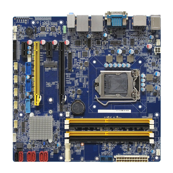
Page 15: Motherboard Layout
RX170Q User’s Manual Place this side towards the rear of the chassis. 1.2.3 Motherboard Layout RX170Q User’s Manual 15... -
Page 16: Layout Content List
Chassis FAN connector 4 x 1 wafer, pitch 2.54mm F_PANEL Intel Front Panel connector 5 x 2 header, pitch 2.54mm EATXPWR1 ATX power connectors 12 x 2 wafer ATX12V1 12V ATX power connectors 2 x 2 wafer 16 RX170Q User’s Manual... -
Page 17: Central Processing Unit (Cpu)
Contact your retailer immediately if the PnP cap is missing, or if you see any damage to the PnP cap/socket pins/motherboard components. BCM Advanced Research will shoulder the cost of repair only if the damage is shipment/transit-related. ... -
Page 18: Installing The Cpu
To prevent damage to the socket pins, do not remove the PnP cap unless you are installing a CPU. 3. Lift the Load lever with your thumb and forefinger to around 180º angle (A), then pull the PnP cap from the CPU socket to remove (B). 18 RX170Q User’s Manual... -
Page 19: Installing The Cpu Heatsink And Fan
CPU! 1.3.2 Installing the CPU Heatsink and Fan Intel® Core™ i7/ i5/ i3 LGA1151 processor requires a specially designed heatsink and fan RX170Q User’s Manual 19... - Page 20 Motherboard hole Orient the heatsink and fan assembly such that the CPU fan cable is closest to the CPU fan connector. Make sure each fastener is oriented as shown, with the narrow groove directed outward. 20 RX170Q User’s Manual...
-
Page 21: Uninstalling The Cpu Heatsink And Fan
Insufficient air flow inside the system may damage the motherboard components. These are not jumpers! DO NOT place jumper caps on the fan connectors. 1.3.3 Uninstalling the CPU Heatsink and Fan To uninstall the CPU heatsink and fan: RX170Q User’s Manual 21... - Page 22 2. Rotate each fastener counterclockwise 3. Pull up two fasteners at a time in a diagonal sequence to disengage the heatsink and fan assembly from the motherboard. 4. Carefully remove the heatsink and fan assembly from the motherboard. 22 RX170Q User’s Manual...
-
Page 23: System Memory
30.35 mm/1.2 in) to make signal routing easier, and the thickness is also increased (to 1.2 mm from 1.0) to accommodate more signal layers.DDR4 DIMM modules have a slightly curved edge connector so not all of the pins are engaged at a time during module insertion, lowering the insertion force. RX170Q User’s Manual 23... -
Page 24: Installing A Dimm
A DDR4 DIMM is keyed with a notch so that it fits in only one direction. DO NOT force a DIMM into a socket to avoid damaging the DIMM. The DDR4 DIMM sockets do not support DDR/DDR2/DDR3 DIMMs. DO NOT install DDR/DDR2/DDR3 DIMMs to the DDR4 DIMM socket. 24 RX170Q User’s Manual... -
Page 25: Removing A Dimm
2. Assign an IRQ to the card if needed. Refer to the tables on the next page. 3. Install the software drivers for the expansion card. 1.5.3 PCI Express x16 slot This motherboard supports one PCI Express x16 slot that complies with the PCI Express specifications. RX170Q User’s Manual 25... -
Page 26: Pci Express X1 Slot
RX170Q User’s Manual 1.5.4 PCI Express x1 slot This motherboard supports one PCIe x1 slot that complies with the PCIe x1 specifications. 1.5.5 Mini PCIe connector Support both Full size or half size mini-PCIe card 26 RX170Q User’s Manual... -
Page 27: Connector
This jumper allows you to clear the Real Time Clock (RTC) RAM in CMOS. You can clear the CMOS memory of date, time, and system setup parameters by erasing the CMOS RTC RAM data. The onboard button cell battery powers the RAM data in CMOS, which includes system RX170Q User’s Manual 27... -
Page 28: At/Atx Power Mode Select (Jpson1)
(CPU Parameter Recall) feature. Shut down and reboot the system so the BIOS can automatically reset parameter settings to default values. 1.6.2 AT/ATX Power Mode Select (JPSON1) This jumper allows you to select ATX Mode or AT mode 28 RX170Q User’s Manual... -
Page 29: Com Power Setting(Jcompwr1~5)
RX170Q User’s Manual AT mode ATX mode (Default) 1.6.3 COM POWER SETTING (JCOMPWR1~5) This jumper allows you to select COM2 to support Ring/+12V/+5V Ring +12V RX170Q User’s Manual 29... -
Page 30: Com6 Master/Slave Terminal Setting(Com6_S1~4)
RX170Q User’s Manual 1.6.4 COM6 Master/Slave terminal Setting (COM6_S1~4) 1.6.5 COM6 type Setting (JSETCOM6) 30 RX170Q User’s Manual... -
Page 31: Lvds Panel Voltage Selection (Jblvol1)
RX170Q User’s Manual 1.6.6 LVDS panel voltage Selection (JBKLVOL1) 1.6.7 LVDS brightness control mode Selection (JLVDS_BKL1) This jumper allows you to select the control mode of LVDS backlight. PWM mode DC mode 1.7 Connectors 1.7.1 Rear panel connectors RX170Q User’s Manual 31... -
Page 32: Rx170Q User's Manual
Description Status Description No link 10Mbps connection Orange Linked Green 100Mbps connection Blinking Data Orange 1Gbps activity connection USB12 USB 3.0 These two 4-pin Universal Serial Bus (USB) Connectors ports are available for connecting USB 3.0 devices. 32 RX170Q User’s Manual... -
Page 33: Cpu And System Fan Connectors (Cpu_Fan, Sys_Fan)
4800rpm or a total of 1A~2.22A (26.64W max.) at +12V. Connect the fan cables to the fan connectors on the motherboard, making sure that the black wire of each cable matches the ground pin of the connector. RX170Q User’s Manual 33... -
Page 34: System Panel (F_Panel)
Insufficient air flow inside the system damage motherboard components. These are not jumpers! DO NOT place jumper caps on the fan connectors. 1.7.3 System Panel (F_PANEL) This connector is for a chassis-mounted front panel. The functions are as following. 34 RX170Q User’s Manual... -
Page 35: Atx Power Connectors (Eatxpwr1 & Atx12V1)
1.7.4 ATX power connectors (EATXPWR1 & ATX12V1) The connector is for ATX power supply plugs. The power supply plugs are designed to fit these connectors in only one orientation. Find the proper orientation and push down firmly until the connectors completely fit. RX170Q User’s Manual 35... -
Page 36: Serial Port Connectors (Com1~5)
1.7.5 Serial Port connectors (COM1~5) This connector is for a serial (COM) port. Connect the serial port module cable to this connector, then install the module to a slot opening at the back of the system chassis. 36 RX170Q User’s Manual... -
Page 37: Serial Ata Connector (Sata1~6 )
1.7.7 USB connectors (USB910, USB1112) These connectors are for USB 2.0 ports. Connect the optional USB module cable to any of these connectors, then install the module to a slot opening at the back of the system chassis. RX170Q User’s Manual 37... -
Page 38: Usb Connector (Usb13)
These connectors are for one USB 2.0 ports. Connect the optional USB module cable to any of these connectors, then install the module to a slot opening at the back of the system chassis. These USB connectors comply with USB 2.0 specification that supports up to 480 Mbps connection speed. 38 RX170Q User’s Manual... -
Page 39: Usb3.0 Connector(Usb56)
2. USB3_RX- 19. +5V 3. USB3_RX+ 18. USB3_RX- 4. GND 17. USB3_RX+ 5. USB3_TX- 16. GND 15. USB3_TX- 6. USB3_TX+ 14. USB3_TX+ 7. GND 13. GND 8. USB- 12. USB- 9. USB+ 11. USB+ 10. NC RX170Q User’s Manual 39... -
Page 40: Lpt Port Connector(Lpt)
20. GND 21. LPT_BUSY 22. GND 23. LPT_PE 24. GND 25.LPT_SLCT 26. NC 1.7.11 LAN LED status connector (LANLED1) 1.+3V_Dual 2.+3V_Dual 3.LAN1_LED 4.GND 5.+3V_Dual 6.+3V_Dual 7.GND 8. GND 9.+3V_Dual 10.+3V_Dual 1.7.12 8 bit GPIO header (JDIO1) 40 RX170Q User’s Manual... -
Page 41: Front Audio Connector (Fp_Audio1)
This connector is for a chassis-mounted front panel audio I/O module that supports either HD Audio or legacy AC ‘97 (optional) audio standard. FP_AUDIO1 9. LINE2L 10. LINE2-JD 8. NC 7. SENSEB 6. MIC2-JD 5. LINE2R 4. +3.3 3. MIC2R 2. GND 1. MIC2L RX170Q User’s Manual 41... -
Page 42: Amplifier Connector(Jamp1)
RX170Q User’s Manual 1.7.14 Amplifier Connector (JAMP1) JAMP1 1. AMP_L- 2. AMP_L+ 3. AMP_R- 4. AMP_R+ 1.7.15 LVDS back light connector (JBKL1) 1. +12V_BL 2. GND 3. BL_EN 4. BRIGHT1 5. +5V_BL 42 RX170Q User’s Manual... -
Page 43: Lvds Connector(Cn3)
14. GND 11. LVDS_A1- 12. LVDS_A0- 9. LVDS_A1+ 10. LVDS_A0+ 7. GND 8. GND 5. DDC_CLK 6. DDC_DATA 3. VDD_+3.3V 4. VDD_+5V 1. VDD_+3.3V 2. VDD_+5V 1.7.17 SM bus connector (JSMB1) 1. SMBCLK 2. SMBDATA 3. GND RX170Q User’s Manual 43... -
Page 44: Chapter 2 - Bios Setup
RX170Q User’s Manual This chapter tells how to change the system settings through the BIOS Setup menus. Detailed descriptions of the BIOS parameters are also provided. BIOS Step 44 RX170Q User’s Manual... -
Page 45: Bios Setup Program
The BIOS setup screens shown in this section are for reference purposes only, and may not exactly match what you see on your screen. Visit the system builder’s website to download the latest BIOS file for this motherboard RX170Q User’s Manual 45... -
Page 46: Legend Box
<F3> to load the optimal default values. While moving around through the Setup program, note that explanations appear in the Item Specific Help window located to the right of each menu. This window displays the help text for the currently highlighted field. 46 RX170Q User’s Manual... -
Page 47: Bios Menu Screen
To access the menu items, press the up/down/right/left arrow key on the keyboard until the desired item is highlighted, then press [Enter] to open the specific menu. RX170Q User’s Manual 47... -
Page 48: Main Setup
Use this menu for basic system configurations, such as time, date etc. BIOS Information Displays the auto-detected BIOS information. System Date The date format is <Date>,<Month>,<Day>,<Year>. System Time The time format is <Hour>,<Minute>,<Second>. 48 RX170Q User’s Manual... -
Page 49: Advanced Bios Setup
The Advanced BIOS Setup screen is shown below. The sub menus are described on the following pages. Take caution when changing the settings of the Advanced menu items. Incorrect field values can cause the system to malfunction. RX170Q User’s Manual 49... -
Page 50: Trusted Computing(Optional)
Schedule and operation for the Security Device. Configuration options: [None] [TPM clear] Platform Hierarchy [Enable] Enable or Disable Platform Hierarchy. Configuration options: [Enable] [Disable] Storage Hierarchy [Enable] Enable or Disable Storage Hierarchy. Configuration options: [Enable] [Disable] 50 RX170Q User’s Manual... -
Page 51: Acpi Settings
ACPI Sleep State [S3 only (Suspend to RAM)] Select the highest ACPI sleep state the system will enter the SUSPEND button is press. Configuration options: [Suspend Disable] [S3 only(suspend to RAM )] S3 Video Repost [Disabled] Enable or disable S3 video repost RX170Q User’s Manual 51... -
Page 52: Amt Configuration
Configuration options: [Disabled] [Enabled] 2.4.3 AMT configuration AMT Configuration settings Intel AMT [Enable] Enable or Disable Intel AMT BIOS extension Configuration options: [Disabled] [Enabled] Un-Configure ME [Disable] Un-configure ME with Password Configuration options: [Disabled] [Enabled] 52 RX170Q User’s Manual... - Page 53 RX170Q User’s Manual 2.4.4 PCH-FW configuration ME firmware information ME state [Enabled] Set ME to soft Temporary Disabled Configuration options: [Disabled] [Enabled] RX170Q User’s Manual 53...
-
Page 54: Ntc6101D Super Io Configuration
RX170Q User’s Manual 2.4.5 NCT6106D Super IO configuration Provide NCT6106D super IO configuration settings 2.4.5.1 Serial Port 1 Configuration Serial Port [Enabled] Enable or Disable serial Port (COM) Configuration options: [Disabled] [Enabled] 54 RX170Q User’s Manual... - Page 55 Serial Port [Enabled] Enable or Disable serial Port (COM) Configuration options: [Disabled] [Enabled] Change Settings [Auto] Select an optimal setting for super IO device Configuration options: as below 2.4.5.3 Serial Port 3 Configuration Serial Port [Enabled] RX170Q User’s Manual 55...
-
Page 56: Serial Port 4 Configuration
Configuration options: as below 2.4.5.4 Serial Port 4 Configuration Serial Port [Enabled] Enable or Disable serial Port (COM) Configuration options: [Disabled] [Enabled] Change Settings [Auto] Select an optimal setting for super IO device Configuration options: as below 56 RX170Q User’s Manual... - Page 57 Configuration options: as below 2.4.5.6 Serial Port 6 Configuration Serial Port [Enabled] Enable or Disable serial Port (COM) Configuration options: [Disabled] [Enabled] Change Settings [Auto] Select an optimal setting for super IO device Configuration options: as below RX170Q User’s Manual 57...
- Page 58 Enable or Disable parallel Port (LPT) Configuration options: [Disabled] [Enabled] Change Settings [Auto] Select an optimal setting for super IO device Configuration options: as below Device mode [STD Printer Mode] Change the printer port mode Configuration options: as below 58 RX170Q User’s Manual...
- Page 59 WatchDog count mode [Second] WatchDog count mode Selection Configuration options: [Second] [Minute] WatchDog Timeout value Fill watchdog timeout value, 0 means disables Chassis opened warning [Disabled] Select chassis intrusion enabled to Disabled Configuration options: [Disabled] [Enabled] RX170Q User’s Manual 59...
-
Page 60: Ntc6106D Hw Moinitor
RX170Q User’s Manual 2.4.6 NCT6106D HW monitor Display Hardware monitor information 60 RX170Q User’s Manual... - Page 61 RX170Q User’s Manual 2.4.6.1 Smart FAN Smart FAN Function [Enabled] Smart fan function Enable/Disabled Configuration options: [Enabled] [Disabled] 2.4.6.1.1 Smart FAN mode Configuration Setting different FAN on this motherboard RX170Q User’s Manual 61...
- Page 62 RX170Q User’s Manual SYS_FAN1/CPU_FAN1/CHA_FAN1 FAN Target [Disabled] Smart FAN target temperature Configuration options: Please see below picture CPU_FAN1 MIN.FAN Speed(%) [50%] CPU Smart FAN minimum settings Configuration options: Please see below picture 62 RX170Q User’s Manual...
-
Page 63: S5 Rtc Wake Settings
RX170Q User’s Manual 2.4.7 S5 RTC wake settings Wake system from S5 [Disabled] Enabled or Disabled system wake on alarm event Configuration options: [Enabled] [Disabled] RX170Q User’s Manual 63... -
Page 64: Cpu Configuration
When enabled, a VWM can utilize the additional hardware capabilities provided by vanderpool Technology Configuration options: [Disabled][Enabled] Intel® SpeedStep™ [Enabled] Allow more than two frequency ranges to be supported. Configuration options: [Disabled][Enabled] Turbo mode [Enabled] Enable or disable Turbo mode Configuration options: [Enabled] [Disabled] 64 RX170Q User’s Manual... -
Page 65: Intel Txt Information
Select owner EPOCH input type [No change in owner EPOCHs] After user enters EPOCH values manually, the values will not be visible for security reasons Configuration options:[No change in owner EPOCHs][change to new random owner EPOCHs][Manual user defined owner EPOCHs] RX170Q User’s Manual 65... - Page 66 RX170Q User’s Manual 2.4.9 Intel TXT information Display Intel TXT information 66 RX170Q User’s Manual...
-
Page 67: Sata Configuration
Designates this port as Hot Pluggable Configuration options: [Disabled][Enabled] Port 2 [Enabled] Enable or Disable SATA port 2 Configuration options: [Enabled][Disabled] Hot Plug [Disabled] Designates this port as Hot Pluggable Configuration options: [Disabled][Enabled] Port 3 [Enabled] RX170Q User’s Manual 67... - Page 68 Hot Plug [Disabled] Designates this port as Hot Pluggable Configuration options: [Disabled][Enabled] Port 6 [Enabled] Enable or Disable SATA port 6 Configuration options: [Enabled][Disabled] Hot Plug [Disabled] Designates this port as Hot Pluggable Configuration options: [Disabled][Enabled] 68 RX170Q User’s Manual...
-
Page 69: Ami Graphic Output Protocol Policy
2.4.11 AMI Graphic Output Protocol Policy Output Select [DP1] Output interface Selection. Configuration Selection: It depends on what kind of monitor you connect to this board. Once you select, there will be single display under BIOS mode. RX170Q User’s Manual 69... -
Page 70: Network Stack Configuration
Enabled IPv6 PXE boot support Configuration options: [Disabled] [Enabled] PXE boot wait time Wait time to press ESC to abort the PXE boot Media Detect Count Number of times presence of media will be checked 70 RX170Q User’s Manual... -
Page 71: Compatibility Support Module Configuration
Control the execution of UEFI and Legacy Video OpROM Configuration options: [Do not launch] [UEFI][Legacy] Other PCI devices [UEFI] Determines OpROM execution policy for devices other than Network, Storage, or Video. Configuration options: [Do not launch] [UEFI][Legacy] RX170Q User’s Manual 71... -
Page 72: Nvme Configuration
RX170Q User’s Manual 2.4.14 NVMe Configuration Display NVMe controller or Drive information 72 RX170Q User’s Manual... -
Page 73: Usb Configuration
Mass storage device emulation type. ‘Auto’ enumerates devices according to their media format. Optical drives are emulated as ‘CDROM’, drives with no media will be emulated according to a drive type. Configuration options: [Auto] [Floopy][Forced FDD][hard Disk][CD-ROM] RX170Q User’s Manual 73... -
Page 74: Chipset
RX170Q User’s Manual 2.5 Chipset 74 RX170Q User’s Manual... -
Page 75: System Agent (Sa) Confuguration
RX170Q User’s Manual 2.5.1 System Agent (SA) Configuration VT-d [Enabled] VT-d capability Configuration options: [Disabled] [Enabled] RX170Q User’s Manual 75... -
Page 76: Graphic Configuration
Internal Graphics [Auto] Keep IGFX enabled based on the setup options Configuration options: [Auto] [disabled][enabled] DVMT Pre-allocated [32M] Select DVMT 5.0 Pre-allocated (Fixed) Graphics memory size used by the internal graphics device. Configuration options: As below picture 76 RX170Q User’s Manual... - Page 77 RX170Q User’s Manual DVMT total Gfx Mem [256M] Select DVMT 5.0 Total graphic memory size used by the internal graphic device Configuration options: [128M][256M][Max] RX170Q User’s Manual 77...
- Page 78 RX170Q User’s Manual 2.5.1.1.1 LCD Control LVDS Control [Disabled] Enabled or Disabled LVDS Configuration options: [Enabled][Disabled] LVDS panel Type[1280x760 18bit single channel] Select LVDS panel type Configuration options: See below picture 78 RX170Q User’s Manual...
- Page 79 RX170Q User’s Manual LVDS DC brightness:30 LVDS DC brightness value from 1 to 63. LVDS PWM brightness:30 LVDS PWM brightness value from 0 to 255. RX170Q User’s Manual 79...
- Page 80 Enable or Disable the root port Configuration options: [Disabled][Enabled][Auto] Max Link Speed [Auto] Configure PEG 0:1:0 Max Speed Configuration options: [Auto][Gen1][Gen2][Gen3] Detect Non-Compliance Device [Disabled] Detect non-compliance PCI express Device in PEG Configuration options: [Disabled][Enabled] 80 RX170Q User’s Manual...
- Page 81 RX170Q User’s Manual 2.5.1.3 Memory configuration Display memeory information Max TOLUD [Dynamic] Maximum value of TOLUD. Configuration options: As above picture RX170Q User’s Manual 81...
-
Page 82: Pch-Io Configuration
Specify what state to go to when power is re-applied after a power failure. Configuration options: [Power on][Power off][Last State] GPIO Group Control [Disabled] Configure the digital GPIO pins Configuration options: [Disabled][Enabled] Amplifier GAIN(db) [15.3db] Select Amplifier GAIN value Configuration options: [15.3db][21.2db][27.2db][31.8db] 82 RX170Q User’s Manual... - Page 83 Configuration options: [Disabled][L0s][L1][L0sL2][Auto] PCIe Speed [Auto] Select PCI Express Port speed Configuration options: [Auto][Gen1][Gen2][Gen3] Detect Non-compliance device [Disabled] Detect non-compliance PCI express Device, If enabled, it will take more time at Post time. Configuration options: [Disabled][Enabled] RX170Q User’s Manual 83...
- Page 84 Configuration options: [Disabled][L0s][L1][L0sL2][Auto] PCIe Speed [Auto] Select PCI Express Port speed Configuration options: [Auto][Gen1][Gen2][Gen3] Detect Non-compliance device [Disabled] Detect non-compliance PCI express Device, If enabled, it will take more time at Post time. Configuration options: [Disabled][Enabled] 84 RX170Q User’s Manual...
- Page 85 Configuration options: [Disabled][L0s][L1][L0sL2][Auto] PCIe Speed [Auto] Select PCI Express Port speed Configuration options: [Auto][Gen1][Gen2][Gen3] Detect Non-compliance device [Disabled] Detect non-compliance PCI express Device, If enabled, it will take more time at Post time. Configuration options: [Disabled][Enabled] RX170Q User’s Manual 85...
- Page 86 Configuration options: [Disabled][L0s][L1][L0sL2][Auto] PCIe Speed [Auto] Select PCI Express Port speed Configuration options: [Auto][Gen1][Gen2][Gen3] Detect Non-compliance device [Disabled] Detect non-compliance PCI express Device, If enabled, it will take more time at Post time. Configuration options: [Disabled][Enabled] 86 RX170Q User’s Manual...
- Page 87 Configuration options: [Disabled][L0s][L1][L0sL2][Auto] PCIe Speed [Auto] Select PCI Express Port speed Configuration options: [Auto][Gen1][Gen2][Gen3] Detect Non-compliance device [Disabled] Detect non-compliance PCI express Device, If enabled, it will take more time at Post time. Configuration options: [Disabled][Enabled] RX170Q User’s Manual 87...
- Page 88 XHCI Disabled Compliance Mode [False] Options to disable compliance mode. Configuration options: [False][true] USB Port Disable override [Disabled] Select Enabled/Disabled the corresponding USB port from reporting a device connection to the controller. Configuration options: [Disabled] [Select Per-Pin] 88 RX170Q User’s Manual...
- Page 89 RX170Q User’s Manual 2.5.2.3 HD audio Configuration HD audio[Auto] Control Detection of the HD-Audio device. Configuration options: [Disabled] [Enabled][Auto] RX170Q User’s Manual 89...
-
Page 90: Security
RX170Q User’s Manual 2.6 Security Administrator Password Set setup Administrator Password User Password Set User Password 90 RX170Q User’s Manual... - Page 91 UEFI USB Key Drive BBS Priorities Specifies the boot device priority sequence from available UEFI USB key Drives. UEFI Network Key Drive BBS Priorities Specifies the boot device priority sequence from available UEFI Network key Drives. RX170Q User’s Manual 91...
- Page 92 Reset the system after saving the changes. Restore Defaults Restore/Load default values for all the setup option. Launch EFI Shell from filesystem device Attempts to launch EFI shell application from one of the available filesystem devices. 92 RX170Q User’s Manual...
Need help?
Do you have a question about the RX170Q and is the answer not in the manual?
Questions and answers