
Subscribe to Our Youtube Channel
Related Manuals for BCM RX77Q


Summary of Contents for BCM RX77Q
- Page 1 RX77Q User’s Manual V1.0 Intel® Q77 Micro ATX Motherboard (uATX) supports 2nd/3rd Gen. 22nm Intel® Core™ i7 / i5 / i3 Processors...
-
Page 2: Trademarks
▍ Preface Copyright Notice Copyright Notice The material in this document is our intellectual property. We take every care in the preparation of this document, but no guarantee is given as to the correctness of its contents. Our products are under continual improvement and we reserve the right to make changes without notice. -
Page 3: Safety Instructions
RX77Q Safety Instructions Safety Instructions ■ Always read the safety instructions carefully. ■ Keep this User’s Manual for future reference. ■ Keep this equipment away from humidity. ■ Lay this equipment on a reliable fl at surface before setting it up. -
Page 4: Ce Conformity
▍ Preface CE Conformity CE Conformity Hereby, we declare that this device is in compliance with the essential safety requirements and other relevant provisions set out in the European Directive. FCC-B Radio Frequency Interference Statement FCC-B Radio Frequency Interference Statement This equipment has been tested and found to comply with the limits for a Class B digital device, pursuant to Part 15 of the FCC Rules. -
Page 5: Weee Statement
RX77Q WEEE Statement WEEE Statement Under the European Union (“EU”) Directive on Waste Electrical and Elec- tronic Equipment, Directive 2002/96/EC, which takes effect on August 13, 2005, products of “electrical and electronic equipment” cannot be discarded as municipal waste anymore and manufacturers of covered electronic equip-... -
Page 6: Table Of Contents
▍ Preface Contents Contents Copyright Notice ................. ii Trademarks ..................ii Safety Instructions ................iii CE Conformity ..................iv FCC-B Radio Frequency Interference Statement ......iv WEEE Statement ................v Chapter 1 Overview ................1-1 Mainboard Specif cations ..............1-2 Mainboard Layout ................1-4 Block Diagram ................. -
Page 7: Chapter 1 Overview
Chapter 1 Overview Thank you for choosing the RX77Q, an excellent in- dustrial computer board. Based on the innovative Intel Cougar Point chipset ® for optimal system ef f ciency, the RX77Q accommo- dates the Intel Core i3/ i5/ i7/ Celeron processor ®... -
Page 8: Mainboard Specif Cations
▍ Mainboard Specifi cations Mainboard Specifi cations ■ (Optional) Chipset ■ ■ Memory ■ ■ SATA ■ ■ RAID ■ Audio ■ ■ ■ Graphics Back Panel I/O ■ ■ ■ ■ ■ ■ ■ ■ ■ ■ ■ Onboard ■... -
Page 9: Form Factor
RX77Q Slot ■ 1 PCIe x16 slot (1st slot) ■ 1 PCIe x1 slot (2nd slot) ■ 1 PCIe x4 slot (3rd slot) ■ 1 PCI slot (4th slot) ■ 1 Mini-PCIe slot Form Factor ■ uATX: 244mm x 244mm Environmental ■... -
Page 10: Mainboard Layout
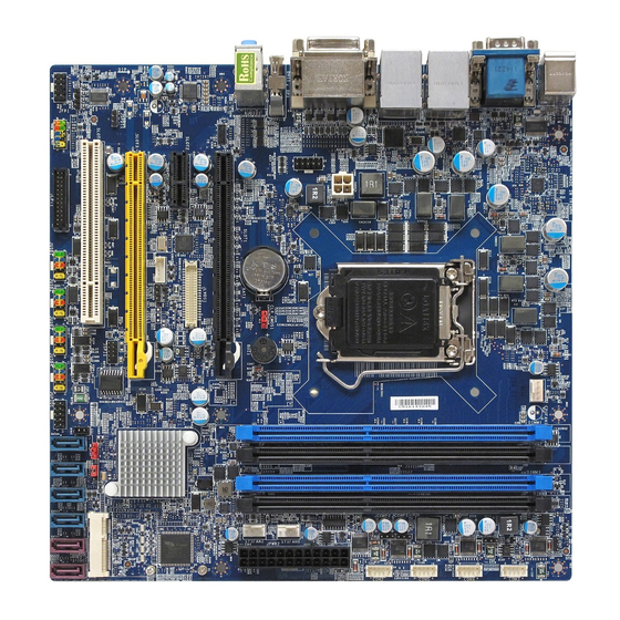
▍ Overview Mainboard Layout Fan Power Connector DIMM Slot COM Power Jumper Power Connector COM Power Jumper Serial Port Connector COM Power Jumper Serial Port Connector Serial Port Connector COM Power Jumper Serial Port Connector 24-pin Power Connector Fan Power Connector Clear CMOS Jumper... -
Page 11: Block Diagram
RX77Q Block Diagram Block Diagram... -
Page 12: Chapter 2 Hardware Setup
Chapter 2 Hardware Setup This chapter provides you with the information on mainboard hardware confi gurations. Incorrect setting of jumpers and connectors may damage your main- board. Please pay special attention not to connect these headers in wrong direction. DO NOT adjust any jumper while the mainboard is powered on. -
Page 13: Quick Components Guide
▍ Hardware Setup Quick Components Guide Quick Components Guide Fan Power CPU, DIMM Slot, COM Power 4-pin Power Connector, COM Power p2-3 p2-6 Jumper, p2-19 Connector, p2-7 p2-12 Jumper, p2-19 Serial Port Connector, p2-15 COM Power Jumper, p2-19 Serial Port Connector, p2-15 COM Power... -
Page 14: Cpu (Central Processing Unit)
RX77Q CPU (Central Processing Unit) CPU (Central Processing Unit) When you are installing the CPU, make sure that you install the cooler to prevent overheating. If you do not have the CPU cooler, consult your dealer before turning on the computer. -
Page 15: Cpu & Cooler Installation
▍ Hardware Setup CPU & Cooler Installation CPU & Cooler Installation When you are installing the CPU, make sure the CPU has a cooler at- make sure the CPU has a cooler at- tached on the top to prevent overheating tached on the top to prevent overheating. - Page 16 RX77Q Secure the lever near the Make sure the four hooks are hook end under the reten- in proper position before you tion tab. install the cooler. Align the holes on the mainboard with the cooler. Push down the cooler until its four clips get wedged into the holes of the mainboard.
-
Page 17: Memory
▍ Hardware Setup Memory Memory These DIMM slots are intended for memory modules. DDR3 DDR3 240-pin, 1.5V 48x2=96 pin 72x2=144 pin Installing Memory Modules The memory module has only one notch on the center and will only fi t in the right orientation. Insert the memory module vertically into the DIMM slot. -
Page 18: Power Supply
RX77Q Power Supply Power Supply 24-Pin Power Connector: JPWR2 This connector allows you to connect an 24-pin power supply. To connect the 24-pin power supply, make sure the plug of the power supply is inserted in the proper orientation and the pins are aligned. Then push down the power supply fi... -
Page 19: Back Panel I/O
▍ Hardware Setup Back Panel I/O Back Panel I/O Line-In Jack Mouse Port Serial Port LAN Jack LAN Jack DVI-D Port Line-Out Jack Mic-In Jack Displayport DVI-D Port Keyboard VGA Port USB 3.0 USB 3.0 Port Port Port ▶ Mouse/Keyboard Port The standard PS/2 mouse/keyboard DIN connector is for a PS/2 mouse/ keyboard. - Page 20 RX77Q ▶ RS-232/422/485 Serial Port Connector (Optional) The serial port is a 16550A high speed communications port that sends/ receives 16 bytes FIFOs. You can attach a serial mouse or other serial devices directly to the connector. RS-232 SIGNAL DESCRIPTION...
- Page 21 ▍ Hardware Setup ▶ The standard RJ-45 LAN jack is for connection to the Local Area Network (LAN). You can connect a network cable to it. Activity Indicator Speed Indicator Left LED Right LED (Active LED) (100M/1000M Speed LED) LED Color Yellow Green/Orange No Transmission...
-
Page 22: Connector
RX77Q Connector Connector Chassis Intrusion Pinheader: CI1 This connector is provided to connect the chassis intrusion switch cable. If the chassis is opened, the chassis intrusion mechanism will be activated. The system will record this status and show a warning message on the screen. - Page 23 ▍ Hardware Setup Audio Amplifi er Pinheader: JAMP1 The JAMP1 is used to connect audio amplifi ers to enhance audio perfor- mance. Fan Power Connector: CPUFAN1, SYSFAN1, SYS- FAN2 The fan power connector supports system cooling fan with +12V. When connecting the wire to the connectors, always note that the red wire is the positive and should be connected to the +12V;...
- Page 24 RX77Q GPIO Pinheader: JGPIO1 This connector is provided for the General-Purpose Input/Output (GPIO) peripheral module. Front Panel Pinheader: JFP1 This front panel connector is provided for electrical connection to the front panel switches & LEDs and is compliant with Intel Front Panel I/O Con- nectivity Design Guide.
- Page 25 ▍ Hardware Setup Front USB Pinheader: JUSB1 ~ JUSB4 This connector, compliant with Intel I/O Connectivity Design Guide, is ideal for connecting high-speed USB interface peripherals such as USB HDD, digital cameras, MP3 players, printers, modems and the like. USB 2.0 Bracket (Optional) Important Important Note that the pins of VCC and GND must be connected correctly to avoid...
- Page 26 RX77Q Serial Port Connector: COM2 ~ COM5 This connector is a 16550A high speed communications port that sends/ receives 16 bytes FIFOs. You can attach a serial device to it through an optional serial port bracket. SIGNAL DESCRIPTION Data Carrier Detect...
- Page 27 ▍ Hardware Setup LVDS Inverter Connector: JINV1 The connector is provided for LCD backlight options. LVDS Connector: JLVDS1 The LVDS (Low Voltage Differential Signal) connector provides a digital in- terface typically used with fl at panels. After connecting an LVDS interface fl...
- Page 28 RX77Q S/PDIF-Out Pinheader: JSPDI1 This connector is used to connect S/PDIF (Sony & Philips Digital Intercon- nect Format) interface for digital audio transmission. Front Audio Pinheader: JAUD1 This connector allows you to connect the front panel audio and is compliant with Intel Front Panel I/O Connectivity Design Guide.
-
Page 29: Jumper
▍ Hardware Setup Jumper Jumper Clear CMOS Jumper: CLR CMOS1 There is a CMOS RAM onboard that has a power supply from an external battery to keep the data of system confi guration. With the CMOS RAM, the system can automatically boot OS every time it is turned on. If you want to clear the system confi... - Page 30 RX77Q AT/ATX Select Jumper: JAT1 This jumper allows users to select between AT and ATX power. JAT1 AT Power ATX Power COM Port Power Jumper: JCOMP1 ~ JCOMP5 These jumpers specify the operation voltage of the onboard serial ports. JCOMP1~5...
-
Page 31: Slot
▍ Hardware Setup Slot Slot PCI-E (Peripheral Component Interconnect Express) Slot The PCIE slot supports the PCIE interface expansion card. Mini PCI-E Slot The Mini PCI-E slot is provided for wireless LAN card, TV tuner card, and Robson NAND Flash card . PCI (Peripheral Component Interconnect) Slot The PCI slot supports LAN card, SCSI card, USB card, and other add-on cards that comply with PCI specifi... -
Page 32: Chapter 3 Bios Setup
Chapter 3 BIOS Setup This chapter provides information on the BIOS Setup program and allows you to configure the system for optimum use. You may need to run the Setup program when: ■ An error message appears on the screen during the system booting up, and requests you to run SETUP. -
Page 33: Entering Setup
▍ BIOS Setup Entering Setup Power on the computer and the system will start POST (Power On Self Test) process. When the message below appears on the screen, press <DEL> key to enter Setup. PRESS DEL TO ENTER SETUP If the message disappears before you respond and you still wish to enter Setup, restart the system by turning it OFF and On or pressing the RESET button. -
Page 34: Control Keys
RX77Q CoNtRol KEYS ← → Select Screen ↑ ↓ Select Item Change Field Select Field General Help Save and Exit Exit GETTING HELP After entering the Setup menu, the first menu you will see is the Main Menu. Main Menu The main menu lists the setup functions you can make changes to. -
Page 35: The Menu Bar
▍ BIOS Setup The Menu Bar ▶ Main Use this menu for basic system configurations, such as time, date etc. ▶ Advanced Use this menu to set up the items of special enhanced features. ▶ Boot Use this menu to specify the priority of boot devices. ▶... -
Page 36: Main
RX77Q Main ▶ System Date This setting allows you to set the system date. The date format is <Day>, <Month> <Date> <Year>. ▶ System Time This setting allows you to set the system time. The time format is <Hour> <Minute> <Second>. - Page 37 ▍ BIOS Setup [LBA/Large Enabling LBA causes Logical Block Address- Mode] ing to be used in place of Cylinders, Heads and Sectors [Block Any selection except Disabled determines the (Multi-Sector number of sectors transferred per block Transfer)] [PIO Mode] Indicates the type of PIO (Programmed Input/Output) [DMA Mode] Indicates the type of Ultra DMA...
-
Page 38: Advanced
RX77Q Advanced ▶ Full Screen Logo Display This BIOS feature determines if the BIOS should hide the normal POST messages with the motherboard or system manufacturer’s full-screen logo. When it is enabled, the BIOS will display the full-screen logo during the boot-up sequence, hiding normal POST messages. - Page 39 ▍ BIOS Setup ▶ Option ROM Messages This item is used to determine the display mode when an optional ROM is initialized during POST. When set to [Force BIOS], the display mode used by AMI BIOS is used. Select [Keep Current] if you want to use the display mode of optional ROM.
- Page 40 RX77Q ▶ Legacy USB Support Set to [Enabled] if you need to use any USB 1.1/2.0 device in the operating system that does not support or have any USB 1.1/2.0 driver installed, such as DOS and SCO Unix. ▶ Audio Controller This setting enables/disables the onboard audio controller.
- Page 41 ▍ BIOS Setup ▶ Intel Virtualization Technology Virtualization enhanced by Intel Virtualization Technology will allow a plat- form to run multiple operating systems and applications in independent partitions. With virtualization, one computer system can function as mul- tiple “Virtual” systems. ▶...
- Page 42 RX77Q ▶ Change Settings Serial Port 1/ 2/ 3/ 4/ 5/ Parallel Port This setting is used to change the address & IRQ settings of the specified serial port. ▶ Mode Select Select an operation mode for the serial port 1.
- Page 43 ▍ BIOS Setup ▶ Smart CPUFAN1/ SYSFAN1 / 2 Function These settings enable/disable the Smart Fan function. Smart Fan is an excellent feature which will adjust the CPU/system fan speed automati- cally depending on the current CPU/system temperature, avoiding the overheating to damage your system.
-
Page 44: Boot
RX77Q Boot ▶ Boot Option #1 / 2 / 3 This setting allows users to set the sequence of boot devices where BIOS attempts to load the disk operating system. ▶ Hard Drive BBS Priorities This setting allows users to set the priority of the specified devices. First press <Enter>... -
Page 45: Security
▍ BIOS Setup Security ▶ Administrator Password Administrator Password controls access to the BIOS Setup utility. ▶ User Password User Password controls access to the system at boot and to the BIOS Setup utility. ▶ Chassis Intrusion The field enables or disables the feature of recording the chassis intrusion status and issuing a warning message if the chassis is once opened. - Page 46 RX77Q ▶ Trusted Computing ▶ Security Support This setting controls the Trusted Platform Module (TPM) designed by the Trusted Computing Group (TCG). TPMs are special-purpose inte- grated circuits (ICs) built into a variety of platforms to enable strong user authentication and machine attestation - essential to prevent inap- propriate access to confidential and sensitive information and to protect against compromised networks.
-
Page 47: Chipset
▍ BIOS Setup Chipset ▶ VT-d This item is used to enable/disable the Intel VT-D technology. ▶ Primary Display This item specifies primary graphics adapter. ▶ DVMT Pre-Allocated This setting defines the DVMT pre-allocated memory. Pre-allocated mem- ory is the small amount of system memory made available at boot time by the system BIOS for video. - Page 48 RX77Q ▶ Primary/ Secondary IGFX - Boot Type Use the field to select the type of device you want to use as the boot display of the system. ▶ DP Panel Type This setting allows you to set your preferences for the boot display device.
-
Page 49: Power
▍ BIOS Setup Power ▶ ACPI Sleep State This item specifies the power saving modes for ACPI function. If your oper- ating system supports ACPI, you can choose to enter the Standby mode in S1 (POS) or S3 (STR) fashion through the setting of this field. ▶... - Page 50 RX77Q ▶ Deep S5 The setting enables/disables the Deep S5 power saving mode. In the Deep S5 state, the Suspend wells are powered off for enhanced power savings. boot is required. No previous content is retained. Other components remain powered so the computer can “wake” on input from the clock, modem, LAN, or USB device.
-
Page 51: Exit
▍ BIOS Setup Exit ▶ Save Changes and Exit Save changes to CMOS and exit the Setup Utility. ▶ Discard Changes and Exit Abandon all changes and exit the Setup Utility. ▶ Discard Changes Abandon all changes. ▶ Optimized Defaults Restore the optimized defaults.
Need help?
Do you have a question about the RX77Q and is the answer not in the manual?
Questions and answers