
Subscribe to Our Youtube Channel
Related Manuals for BCM RX35Q


Summary of Contents for BCM RX35Q
- Page 1 Micro-ATX RX35Q Intel® Core™ 2 Quad/ Core™ 2 Duo/ Pentium® 4/ Pentium® D w/ 1333/1000/800MHz FSB User’s Manual First Edition – Jan 2008...
- Page 2 For detailed information, please always refer to the electronic user's manual. Copyright Notice Copyright © 2008 BCM Advanced Research, ALL RIGHTS RESERVED. No part of this document may be reproduced, copied, translated, or transmitted in any form or by any means, electronic or mechanical, for any purpose, without the prior written permission of the original manufacturer.
-
Page 3: Bcm Customer Services
BCM has come to be known. Your satisfaction is our primary concern. Here is a guide to BCM customer services. To ensure you get the full benefit of our services, please follow the instructions below carefully. -
Page 4: Technical Support
BCM assumes no liability under the terms of this warranty as a consequence of such events. Because of BCM high quality-control standards and rigorous testing, most of our customers never need to use our repair service. If any of BCM products is defective, it will be repaired or replaced at no charge... - Page 5 This manual describes in detail the BCM RX35Q Main board. We strongly recommend that you study this manual carefully before attempting to interface with RX35Q or change the standard configurations. Whilst all the necessary information is available in this manual we would recommend that unless you are confident, you contact your supplier for guidance.
- Page 6 Safety Precautions Warning! Always completely disconnect the power cord from your chassis whenever you work with the hardware. Do not make connections while the power is on. Sensitive electronic components can be damaged by sudden power surges. Only experienced electronics personnel should open the PC chassis.
-
Page 7: Table Of Contents
Contents Chapter 1: System Setup ....................Welcome! ............................11 Packing Contents..........................11 Special Features ...........................12 1.3.1 Product Highlights.........................12 Before you proceed........................14 Mainboard Overview ........................15 1.5.1 Placement direction ........................15 1.5.2 Screw Holes ..........................15 1.5.3 Mainboard Layout .........................16 Central Processing Unit (CPU) .....................17 1.6.1 Installing the CPU .........................18 1.6.2 Installing the CPU Heatsink and fan .....................20... - Page 8 1.10.10 S/PDIF-Out Connector: JSPD1.....................35 1.10.11 IEEE1394 Connector: J1394_1 ....................35 1.10.12 Front Panel Connectors: JFP1, JFP2 ...................36 1.11 Jumpers ............................37 1.11.1 Clear CMOS Jumpers: JBAT1 ......................37 1.11.2 BIOS Flash Protection: JCI2 ......................37 1.11.3 The Header: JSPI1 ........................37 1.12 The Expansion Slots ........................38 1.12.1 Installation of expansion card .......................38 1.12.2...
- Page 9 Mainboard Specifications Model RX35Q Processor Intel® Core 2 Processor Socket 775 supports Core 2 Quad, Core 2 Duo, Pentium D CPU Supports CPU FSB 800/1066/1333 MHz North Bridge Intel® DDR2 800/667 SDRAM Memory * Supports DDR2 667 (PC2-5300), DDR2 800 (PC2-6400) memory modules up to 8GB max.
- Page 10 Expansion Slots PCI-E 1 x PCI-E x 16 Slot supports PCI-E x16 Graphic card or ADD2-DVI card 1 x PCI-E x 1 Slot 2 x PCI slot Onboard I/O Headers 1 x IDE Connector SATA 5 x Std. SATA Connectors *SATA1, SATA3, SATA4, SATA5 through Intel®...
-
Page 11: Chapter 1: System Setup
This chapter describes the motherboard features and the new technologies it supports 1.1 Welcome! The motherboard delivers a host of new features and latest technologies, making it another line of BCM long life motherboards! Before you start installing the motherboard, and hardware devices on it, check the items in your package with the list below. -
Page 12: Special Features
1.3 Special Features 1.3.1 Product Highlights Intel® Core 2 Processor Ready This mainboard supports the latest Intel® Core 2 processor in the LGA775 package. With the new Intel® Core 2 micorarchitecture technology and 1333/1066/800 MHz FSB, Intel® Core 2 processor is one of the most powerful and energy efficient CPU in the world. - Page 13 USB 2.0 Technology The mainboard implements the Universal Serial Bus (USB) 2.0 specification, dramatically increasing the connection speed from the 12Mbps bandwidth on USB1.1 to a fast 480Mbps on USB2.0. USB2.0 is backward compatible with USB1.1.
-
Page 14: Before You Proceed
1.4 Before you proceed Take note of the following precautions before you install motherboard components or change any motherboard settings. • Unplug the power cord from the wall socket before touching any component. • Use a grounded wrist strap or touch a safely grounded object or to a metal object, such as the power supply case, before handling components to avoid damaging them due to static electricity •... -
Page 15: Mainboard Overview
1.5 Mainboard Overview Before you install the mainboard, study the configuration of your chassis to ensure that the motherboard fits into it. Make sure to unplug the power cord before installing or removing the mainboard. Failure to do so can cause you physical injury and damage mainboard components. 1.5.1 Placement direction When installing the mainboard, make sure that you place it into the chassis in the correct orientation. -
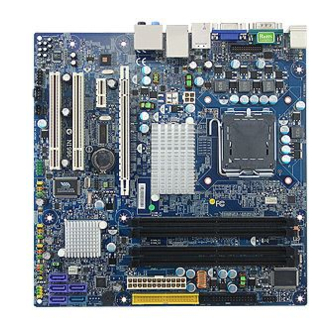
Page 16: Mainboard Layout
1.5.3 Mainboard Layout... -
Page 17: Central Processing Unit (Cpu)
PnP cap/socket pins/motherboard components. BCM will shoulder the cost of repair only, if the damage is shipment/ transit-related. • Keep the PnP cap after installing the mainboard. BCM will process Return Merchandise Authorization (RMA) requests only if the mainboard comes with the cap on the LGA775 socket. -
Page 18: Installing The Cpu
1.6.1 Installing the CPU To install a CPU 1. Locate the CPU socket on the motherboard 2. Press the load lever with your thumb (A) and move it to the left (B) until it is released from the retention tab. To prevent damage to the socket pins, do not remove the PnP cap unless you have installed the CPU. - Page 19 4. Lift the load plate with your thumb and forefinger to a 100° angle (A), then push the PnP cap from the load plate window to remove (B). 5. Position the CPU over the socket, making sure the gold triangle is on the bottom-left corner of the socket.
-
Page 20: Installing The Cpu Heatsink And Fan
1.6.2 Installing the CPU heatsink and fan The Intel Pentium 4 LGA775 processor requires a specially designed heatsink and fan assembly to ensure optimum thermal condition and performance. • When you buy a boxed Intel® Core 2 processor, the package includes the CPU fan and heatsink assembly. - Page 21 Push down two fasteners at a time in a diagonal sequence to secure the heatsink and fan assembly in place 3. Connect the CPU fan cable to the connector on the motherboard labeled CPUFAN1. Do not forget to connect the CPU fan connector! Hardware monitoring errors can occur if you fail to plug in this connector.
-
Page 22: Uninstalling The Cpu Heatsink And Fan
1.6.3 Uninstalling the CPU heatsink and fan. To uninstall the CPU heatsink and fan: 1. Disconnect the CPU fan cable from the connector on the motherboard. 2. Rotate each fastener counterclockwise. 3. Pull up two fasteners at a time in a diagonal sequence to disengage the heatsink and fan assembly from the mainboard. - Page 23 4. Rotate each fastener clockwise to ensure correct orientation when reinstalling. The narrow end of the groove should point outward after resetting. (The photo shows the groove shaded for emphasis.)
-
Page 24: System Memroy
1.7 System Memory 1.7.1 Overview The mainboard comes with four 240-pin DDR2 Dual Inline Memory Modules (DIMM) sockets. You may use 667MHz (PC2-5300), or 800MHz (PC2-6400); Non-ECC, Un-buffered 1.8V DDR2 memory modules on this board (2GB maximum for each slot). It is recommended to use 667MHz DIMM for 8GB configuration. 1.7.2 Dual-Channel mode Population Rule In Dual-Channel mode, the memory modules can transmit and receive data with two data bus lines simultaneously. -
Page 25: Installing Dimm
1.7.3 Installing DIMM Make sure to unplug the power supply before adding or removing DIMMS or other system components. Failure to do so may cause severe damage to both the mainboard and the components. 1. Unlock a DIMM socket by pressing the retaining clips outward. 2. -
Page 26: Removing A Dimm
3. DDR2 memory modules are not interchangeable with DDR and is DDR2 standard is not backward compatible. You shall always install DDR2 memory modules in the DDR2 memory slots. 4. To enable the system boot-up successfully, always inset the memory module into the DMM_A1 slot first. -
Page 27: Power Supply
1.8 Power Supply 1.8.1 ATX 24-pin Power Connector: JPWR3 This connector connects to an ATX 24-pin connector from power supply unit (PSU). To connect the ATX 24-pin power connector, make sure the 24-pin power connector from PSU is inserted in the proper orientation and the pins are aligned. - Page 28 1. For a fully configured system, we recommend that you use a power supply unit (PSU) that complies with ATX 12 V specification 2.0 ( or later version) and provides a minimum power of 350W. 2. Do not forget to connect the 4-pin JPW1 power plug; otherwise, the system will not boot.
-
Page 29: Back Panel
1.9 Back Panel • Mouse/Keyboard Connector The standard PS/2 ® mouse/ keyboard DIN connector is for a PS/2® mouse/ keyboard. • USB Port The USB (Universal Serial Bus) port is for attaching USB devices such as keyboard, mouse, or other USB compatible devices. - Page 30 • Audio Ports These audio connectors are used for audio devices. You can differentiate the color of the audio jacks for different audio sound effects. ▪ Line-In (Blue color): is used for external CD player, tape player or other audio devices. ▪...
-
Page 31: Connectors/Headers
1.10 Connectors/ Headers 1.10.1 Floppy Disk Drive Connector: FDD1 This connector supports 360KB, 720KB, 1.2MB, 1.44MB, or 2.88MB floppy disk drive. 1.10.2 IDE Connector: IDE1 (Through Marvell 88SE6111) This connector supports IDE hard disk drives, optical disk drives and other IDE devices. If you install two IDE devices on the same cable, you must configure the drives separately to master/ slave mode by setting jumpers. -
Page 32: Serial Ata Connectors: Sata1, Sata3, Sata4, Sata5, Sata2
1.10.3 Serial ATA Connectors: SATA1, SATA3, SATA4, SATA5 (Through Intel ICH9) SATA2 (Through Marvell 88SE6111) Please do not fold the Serial ATA cable into 90-degree angle. Otherwise, data loss may occur during transmission. 1.10.4 Fan Power Connectors: CPUFAN1, SYSFAN1 The fan power connectors support system cooling fan with +12V. When connecting the wire to these fan connectors, please note that the red wire is designated as “Power”... -
Page 33: Chassis Intrusion Switch Header: Jci1
1.10.5 Chassis Intrusion Switch Connector: JCI1 This connector connects to a 2-pin chassis switch. If the chassis is opened, the switch will be short. The system will record this status and show a warning message on the screen. To clear the warning message, you must enter the BIOS and clear the record. 1.10.6 CD-In Connector: JCD_IN1 This connector is provided for external audio input. -
Page 34: Front Usb Connectors: Jusb1, Jusb2, Jusb3
1.10.8 Front USB Connectors: JUSB1, JUSB2, JUSB3 This connector is compliant with Intel® I/O Connectivity Design Guide, which is ideal for connecting high-speed USB peripherals such as USB HDD, USB digital cameras, USB MP3 players, USB printers, etc. Be sure the pins of VCC and GND is connected to the connector correctly. Otherwise, it may cause damage to the USB port and/or the connected USB device. -
Page 35: S/Pdif-Out Connector: Jspd1
1.10.10 S/PDIF-Out Connector: JSPD1 This connector is used to connect S/PDIF (Sony & Philips Digital Interconnect Format) interface for digital audio transmission. 1.10.11 IEEE1394 Connector: J1394_1 This connector allows you to connect the IEEE1394 device via an optional IEEE 1394 bracket. -
Page 36: Front Panel Connectors: Jfp1, Jfp2
1.10.12 Front Panel Connectors: JFP1, JFP2 These connectors are for electrical connections to the front panel switches and LEDs. The JFP1 is compliant with Intel® Front Panel I/O Connectivity Design Guide. -
Page 37: Jumpers
1.11 Jumpers 1.11.1 Clear CMOS Jumper: JBAT1 There is a CMOS RAM onboard that has a power supply from an external battery to keep the data of system configuration. For normal state (default), the jumper is set on pin location 1 and 2. To clear the CMOS, set the jumper to pin location 2 and 3 for at least 30 seconds while the system is off. -
Page 38: The Expansion Slots
1.12 The Expansion Slots In the future, you may need to install expansion cards. The following sub-sections describe the expansion slots and the expansion cards that they support. Make sure to unplug the power cord before adding or removing expansion cards. Failure to do so may cause you physical injury and damage mainrboard components. -
Page 39: Pci-Ex16 Slot: Pci-E3
1.12.3.1 PCI-E x 16 Slot: PCI-E3 This slot supports PCI-E x16 graphic cards or ADD2-DVI cards. 1.12.3.2 PCI-E x1 Slot: PCI-E1 This slot supports PCI-E x1 cards. 1.12.4 PCI Slots: PCI1, PCI2 The PCI slot supports LAN card, SCSI card, USB card, and other add-on cards that comply with PCI specifications. -
Page 40: Chapter 2: Starting Up The System
Chapter 2: Starting Up the System 2.1 Starting Up Your System After all connections are made, close your computer case cover. Be sure all the switches are off, and check that the power supply input voltage is set to the local voltage, usually in-put voltage is 220V∼240V or 110V∼120V depending on your country’s voltage used. - Page 41 “Shut down” and then click “Shut down the computer” The power supply should turn off after windows shut down.
-
Page 42: Chapter 3: Bios Setup
Chapter 3: BIOS Setup 3.1 Introducing BIOS The BIOS is a program located on a Flash Memory on the motherboard. This program is a bridge between motherboard and operating system. When you start the computer, the BIOS program gains control. The BIOS first operates an auto-diagnostic test called POST (power on self test) for all the necessary hardware, it detects the entire hardware device and configures the parameters of the hardware synchronization. -
Page 43: Getting Help
3.3 Getting Help Main Menu The main menu lists the setup functions you can make changes to. You can use the arrow keys to select the item. The on-line description of the highlighted setup function is displayed at the bottom of the screen. Sub- Menu If you find a right pointer symbol (as shown in the picture below) appears to the left of certain fields that means a sub-menu can be launched from this field. -
Page 44: The Main Menu
3.4 The Main Menu • Standard CMOS Features Use this menu for basic system configurations, such as time, date, etc. • Advanced BIOS Features Use this menu to setup the items of AMI® special enhanced features. • Integrated Peripherals Use this menu to specify your settings for integrated peripherals. •... - Page 45 • Frequency/ Voltage Control Use this menu to specify your settings for frequency/ voltage control and overclocking. • Load Fail-Safe Defaults Use this menu to load the default values set by the BIOS vendor for stable system performance. • Load Optimized Defaults Use this menu to load the default values set by the mainboard manufacturer specifically for optimal performance of the mainboard.
-
Page 46: Standard Cmos Features
3.5 Standard CMOS Features The items in standard CMOS Features Menu include some basic setup items. Use the arrow keys to highlight the item and then use the <PgUp> or <PgDn> keys to select the value you want in each item. •... - Page 47 • SATA1/ 2/ 3/ 4/ 5 Press <Enter> to enter the sub-menu, and the following screen appears: (SATA1, SATA3, SATA4, SATA5 are controlled through Intel ICH9; SATA2 is controlled through Marvell 88SE6111) • Device/ Vendor/ Size It will showing the device information that you connected to the SATA connector. •...
- Page 48 • Floppy Drive A This item allows you to set the type of floppy drives installed. Available options: [None], [360K, 5.25in.], [1.2M, 5.25in.], [720k, 3.5in.], [1.44M, 3.5in.], [2.88M, 3.5in.]. • System Information Press <Enter> to enter the sub-menu, and the following screen appears: This sub-menu shows the CPU information, BIOS version and memory status of your system (read only).
-
Page 49: Advanced Bios Features
3.6 Advanced BIOS Features • Boot Sector Protection This function protects the BIOS from accidental corruption by unauthorized users or computer viruses. When enabled, the BIOS’s data cannot be changed when attempting to update the BIOS with a Flash utility. To successfully update the BIOS, you’ll need to disable this Flash BIOS Protection function. - Page 50 This setting is to set the Num Lock status when the system is powered on. Setting to [On] will turn on the Num Lock key when the system is powered on. Setting to [Off] will allow users to use the arrow keys on the numeric keypad.
- Page 51 • Chipset Feature Press <Enter> to enter the sub-menu and the following screen appears: • HPET The HPET (High Precision Event Timers) is a component that is part of the chipset. Enabling this feature will provide you with the means to get to it via the various ACPI methods. •...
- Page 52 • Boot Sequence Press <Enter. To enter the sub-menu and the following screen appears: • 1 Boot Device The items allow you to set the first/ second/ third boot device where BIOS attempts to load the disk operating system. • Boot From Other Device Setting the option to [Yes] allows the system to try to boot from other device.
-
Page 53: Integrated Peripherals
3.7 Integrated Peripherals • USB Controller This setting allows you to enable/ disable the onboard USB controller. • USB Device Legacy Support Select [Enabled] if you need to use a USB-interfaced device in the operating system. • Onboard LAN Controller This item is used to enable/ disable the onboard LAN controller. - Page 54 Set this option to [Enable] to specify that the IDE controller on the PCI local bus has bus mastering capability. • RAID Mode (for ICH9R only, which is optional on RX35Q board) The SATA RAID Mode supports RAID 0, 1, 5, 10. I AHCI is chosen, it allows you to enable SATA Stagger Spinup Support (not RAID mode) and take all hard disks on board as master.
-
Page 55: Power Management Setup
3.8 Power Management Setup S3-related functions described in this section are available only when your BIOS supports S3 sleep mode. • ACPI Function This item is to activate the ACPI (Advanced Configuration and Power Management Interface) Function. If your operating system is ACPI-aware, such as Windows 2000/XP, select [Enabled]. •... - Page 56 hardware components turn off to save energy. The information stored in memory will be used to restore the system when a “wake up” event occurs. • Suspend Time Out (Minute) If system activity is not detected for the length of time specified in this field, all devices except CPU will be shut off.
- Page 57 • Resume From S3 By PS/2 Mouse This setting determines whether the system will be awakened from what power saving modes when input signal of the PS/2 mouse is detected. • Resume By PCI Device (PME#) When set to [Enabled], the feature allows your system to be awakened from the power saving modes through any event on PME (Power Management Event).
-
Page 58: Pnp/Pci Configurations
3.9 PnP/PCI Configurations This section describes configuring the PCI bus system and PnP (Plug & Play) feature. PCI, or Peripheral Component Interconnect, is a system which allows I/O devices to operate at speeds nearing the speed the CPU itself uses when communicating with its special components. This section covers some very technical items and it is strongly recommended that only experienced users should make any changes to the default settings. - Page 59 • IRQ Resource Setup Press <Enter> to enter the sub-menu and the following screen appears: • IRQ 3/ 4/ 5/ 7/ 9/ 10/ 11/ 14/ 15 These items specify the bus where the specified IRQ line is used. The settings determine if AMI BIOS should remove an IRQ from the pool of available IRQs passed to devices that are configurable by the system BIOS.
-
Page 60: H/W Monitor
3.10 H/W Monitor • Chassis Intrusion The field enables or disables the feature of recording the chassis intrusion status and issuing a warning message if the chassis is once opened. To clear the warning message, set the field to [Reset]. The setting of the field will automatically return to [Enabled] later. -
Page 61: Frequency/Voltage Control
3.11 Frequency/Voltage Control Change these settings only if you are familiar with the chipset. • Current CPU/ DARM Frequency These items show the current clocks of CPU and Memory speed. Read-only. • Intel EIST The Enhanced Intel SpeedStep technology allows you to set the performance level of the microprocessor whether the computer is running on battery or AC power. - Page 62 • Adjusted CPU Frequency This item shown the CPU frequency after you adjusted. You need to restart the system to load the new CPU frequency you choose. (read only).
-
Page 63: Load Fail-Safe/ Optimized Defaults
3.12 Load Fail-Safe/ Optimized Defaults The two options on the main menu allow users to restore all of the BIOS settings to the default Fail-Safe or Optimized values. The Optimized Defaults are the default values set by the mainboard manufacturer specifically for optimal performance of the mainboard. -
Page 64: Bios Setting Password
3.13 BIOS Setting Password When you select this function, a message as below will appear on the screen: Type the password, up to six characters in length, and press <Enter>. The password typed now will replace any previously set password from CMOS memory. You will be prompted to confirm the password. Retype the password the press <Enter>.
Need help?
Do you have a question about the RX35Q and is the answer not in the manual?
Questions and answers