Table of Contents
Advertisement
Quick Links
RX45Q
®
®
Intel
Q45 LGA775 socket for Intel
Core™ 2 Quad Micro ATX
Motherboard
User's Manual
Ver. 1.01
BCM Advanced Research, An Industrial Leader Since 1990 in Industrial Motherboards & Systems
7 Marconi, Irvine, CA 92618 USA | www.bcmcom.com | (PH)949.470.1888 | (FAX)949.470.0971
For Tech Support, please visit http://www.bcmcom.com/bcm_support_legacyProductSupport.htm or contact
BCMTechSupport@bcmcom.com
Advertisement
Table of Contents

Related Manuals for BCM RX45Q


Summary of Contents for BCM RX45Q
- Page 1 Core™ 2 Quad Micro ATX Motherboard User’s Manual Ver. 1.01 BCM Advanced Research, An Industrial Leader Since 1990 in Industrial Motherboards & Systems 7 Marconi, Irvine, CA 92618 USA | www.bcmcom.com | (PH)949.470.1888 | (FAX)949.470.0971 For Tech Support, please visit http://www.bcmcom.com/bcm_support_legacyProductSupport.htm or contact BCMTechSupport@bcmcom.com...
-
Page 2: Table Of Contents
RX45Q User’s Manual Contents Contents ...........................2 FCC Statement.........................4 Notice............................4 Copyright Notice........................4 Trademark Acknowledgement....................4 Disclaimer..........................4 Life Support Policy ........................5 BCM Customer Services ......................5 Product Warranty ........................6 Manual Objectives........................6 Safety Precautions ........................6 Document Amendment History....................7 Chapter 1 ......................8 RX45Q Specifications ......................9 Block Diagram ........................12 Before you proceed....................... - Page 3 RX45Q User’s Manual 1.1.15 PCI Express X4 Slot ........................29 1.1.16 PCI Express X1 Slot ........................29 Jumpers..........................30 1.1.17 Clear CMOS (CLRTC1) ......................30 1.1.18 Chassis Intrusion Connector (CHSSIS1)................... 31 1.1.19 COM1, COM2 Power Setting & RI/+12V/+5V Select (COM1 PWR, COM2 PWR) ....31 1.1.20...
-
Page 4: Fcc Statement
American Megatrends Inc. • Disclaimer BCM Advanced Research reserves the right to make changes, without notice, to any product, including circuits and/or software described or contained in this manual in order to improve design and/or performance. -
Page 5: Life Support Policy
Our dealers are well trained and ready to give you the support you need to get the most from your BCM products. In fact, most problems reported are minor and are able to be easily solved over the phone. -
Page 6: Product Warranty
Because of BCM high quality-control standards and rigorous testing, most of our customers never need to use our repair service. If any of BCM products is defective, it will be repaired or replaced at no charge during the warranty period. For out-of-warranty repairs, you will be billed according to the cost of replacement materials, service time, and freight. -
Page 7: Document Amendment History
RX45Q User’s Manual Always ground yourself to remove any static charge before touching the motherboard. Modern electronic devices are very sensitive to static electric charges. As a safety precaution, use a grounding wrist strap at all times. Place all electronic components in a static-dissipative surface or static-shielded bag when they are not in the chassis. -
Page 8: Chapter 1
RX45Q User’s Manual Chapter 1 This chapter describes the motherboard features and the new technologies it supports. Product Introduction... -
Page 9: Rx45Q Specifications
RX45Q User’s Manual RX45Q Specifications System Intel® LGA775 socket for Intel® Core™2 Quad / Core™2 Duo Processors Support Intel® next generation 45nm Multi-Core CPU up to 95W TDP 1333 / 1066 / 800 MHz BIOS Award 32 Mb SPI BIOS... - Page 10 RX45Q User’s Manual Audio Audio Codec Realtek® ALC888, 5.1+2 CH. with two independent Streaming Audio Interface Line-out, Line-in, Mic-in TPA3005D2 6W Stereo audio amplifier Audio Amplifier (W) Onboard I/O Headers SATA 6 x SATA connectors 4 x USB connectors (PH:2.54mm)support additional 8 USB ports...
- Page 11 RX45Q User’s Manual 1.40 lbs (0.64 Kg) Size (L x W) * Specifications are subject to change without notice.
-
Page 12: Block Diagram
RX45Q User’s Manual Block Diagram... -
Page 13: Before You Proceed
RX45Q User’s Manual Before you proceed Take note of the following precautions before you install motherboard components or change any motherboard settings. Unplug the power cord from the wall socket before touching any component. Use a grounded wrist strap or touch a safely grounded object or a metal object,... -
Page 14: Motherboard Overview
RX45Q User’s Manual Motherboard Overview Before you install the motherboard, study the configuration of your chassis to ensure that the motherboard fits into it. Refer to the chassis documentation before installing the motherboard. Make sure to unplug the power cord before installing or removing the motherboard. -
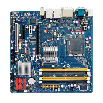
Page 15: Motherboard Layout
RX45Q User’s Manual Motherboard Layout Motherboard Layout... -
Page 16: 1.1.3 Layout Content List
RX45Q User’s Manual 1.1.3 Layout Content List Slots Label Function Note Page DIMM_A1 240-pin DIMM slot 1 DIMM_A2 240-pin DIMM slot 2 DIMM_B1 240-pin DIMM slot 3 DIMM_B2 240-pin DIMM slot 4 PCIEX1 PCI express x1 slot PCIEX4 PCI express x4 slot... - Page 17 RX45Q User’s Manual Internal Connector Label Function Note Page AAFP1 Front Panel Audio Connector 5 x 2 header, pitch 2.54mm ATX12V1 ATX Power Connector 2 x 2 header CHA_FAN Chassis Fan Connector 3 x 1 wafer, pitch 2.54mm CPU_FAN1 CPU Fan Connector 4 x 1 wafer, pitch 2.54mm...
-
Page 18: Central Processing Unit (Cpu)
RX45Q User’s Manual Central Processing Unit (CPU) The motherboard comes with a surface mount LGA775 socket designed for the Intel® LGA775 socket for Intel® Core™2 Quad / Core™2 Duo CPU processors. Make sure the AC power is off before you install the CPU. -
Page 19: Installing The Cpu
RX45Q User’s Manual 1.1.3 Installing the CPU Locate the CPU socket on the motherboard. Before installing the CPU, make sure that the socket box is facing towards you and the load lever is on your left. Press the load lever with your thumb (A), then move it to the left (B) until it is released from the retention tab. - Page 20 RX45Q User’s Manual Lift the load plate with your thumb and forefinger to a 100º angle (A), then push the PnP cap from the load plate window to remove (B). Position the CPU over the socket, making sure that the gold triangle is on the bottom-left corner of the socket then fit the socket alignment key into the CPU notch.
-
Page 21: Installing The Cpu Heatsink And Fan
RX45Q User’s Manual 1.1.4 Installing the CPU Heatsink and Fan The Intel® LGA775 socket for Intel® Core™2 Quad / Core™2 Duo CPU processors require a specially designed heatsink and fan assembly to ensure optimum thermal condition and performance. Install the motherboard to the chassis before you install the CPU fan and heatsink assembly. - Page 22 RX45Q User’s Manual Push down two fasteners at a time in a diagonal sequence to secure the heatsink and fan assembly in place. Connect the CPU fan cable to the connector on the motherboard labelled CPU_FAN1. Do not forget to connect the fan cables to the fan connectors. Insufficient air flow inside the system may damage the motherboard components, and hardware monitoring errors can occur if you fail to plug this connector.
-
Page 23: Uninstalling The Cpu Heatsink And Fan
RX45Q User’s Manual 1.1.5 Uninstalling the CPU Heatsink and Fan Disconnect the CPU fan cable from the connector on the motherboard. Rotate each fastener counter-clockwise. Pull up two fasteners at a time in a diagonal sequence to disengage the heatsink and fan... - Page 24 RX45Q User’s Manual Rotate each fastener clockwise to ensure correct orientation when reinstalling. The narrow end of the groove should point outward after resetting. (The photo shows the groove shaded for emphasis.) Refer to the documentation in the boxed or stand-alone CPU fan package for...
-
Page 25: System Memory
RX45Q User’s Manual System Memory 1.1.6 DIMM Sockets Location The motherboard comes with four 240-pin Double Data Rate 2 (DDR2) Dual Inline Memory Modules (DIMM) sockets. A DDR2 module has the same physical dimensions as a DDR DIMM but has a 240-pin footprint compared to the 184-pin DDR DIMM. -
Page 26: Installing A Ddr2 Dimm
RX45Q User’s Manual Recommended memory configuration Channel Socket Channel A DIMM_A1 and DIMM_A2 Channel B DIMM_B1 and DIMM_B2 1.1.8 Installing a DDR2 DIMM Make sure to unplug the power supply before adding or removing DIMMs or other system components. Failure to do so may cause severe damage to both the motherboard and the components. -
Page 27: Removing A Ddr2 Dimm
RX45Q User’s Manual 1.1.9 Removing a DDR2 DIMM Simultaneously press the retaining clips outward to unlock the DIMM. Remove the DIMM from the socket. Support the DIMM lightly with your fingers when pressing the retaining clips. The DIMM might get damaged when it flips out with extra force. -
Page 28: Standard Interrupt Assignments
RX45Q User’s Manual 1.1.12 Standard Interrupt Assignments Priority Standard Function System Timer Keyboard Controller Redirect to IRQ#9 Communications Port (COM2) Communications Port (COM1)* LAN1 - 82567LM (iAMT) Reserved Printer Port (LPT)* System CMOS/Rear Time Multimedia device (Audio) IRQ holder for PCI streeing*... -
Page 29: Pci Express X16 Slot
RX45Q User’s Manual 1.1.14 PCI Express X16 Slot This motherboard supports one PCI Express x16 graphic card that complies with the PCI Express specifications. The figure shows a graphics card installed on the PCI Express x16 slot. Onboard DVI (DVI-I & DVI-D) will be disabled when PCI-Ex16 card installed. -
Page 30: Jumpers
RX45Q User’s Manual Jumpers 1.1.17 Clear CMOS (CLRTC1) This jumper allows you to clear the Real Time Clock (RTC) RAM in CMOS. You can clear the CMOS memory of date, time, and system setup parameters by erasing the CMOS RTC RAM data. -
Page 31: Chassis Intrusion Connector (Chssis1)
RX45Q User’s Manual 1.1.18 Chassis Intrusion Connector (CHSSIS1) 1.1.19 COM1, COM2 Power Setting & RI/+12V/+5V Select (COM1 PWR, COM2 PWR) RI (Default) +12V COM1 PWR COM2 PWR... -
Page 32: At/Atx Power Mode Select (Pson1)
RX45Q User’s Manual 1.1.20 AT/ATX Power Mode Select (PSON1) ATX Mode (Default) AT Mode This function has need BIOS setting at the same time. Please refer to Chapter 2 BIOS setup / Power Management Setup / Power Type. Connectors 1.1.21... - Page 33 RX45Q User’s Manual table below for the LAN port LED indications. The optional 10/100 Mbps LAN controller allows 10/100 Mbps connection to a Local Area Network (LAN) through a network hub. ACT / LINK LED SPEED LED Status Description Status...
-
Page 34: Front Panel Audio Connector (Aafp1)
RX45Q User’s Manual 1.1.22 Front Panel Audio Connector (AAFP1) This connector is for a chassis-mounted front panel audio I/O module that supports either HD Audio or legacy AC ‘97 (optional) audio standard. Connect one end of the front panel audio I/O module cable to this connector. -
Page 35: Chassis Fan / System Fan Connector (Cha_Fan, Sys_Fan)
RX45Q User’s Manual Important notes on the Motherboard Power Requirements Make sure that your ATX 12V power supply can provide 8A on the +12V lead and at least 1A on the +5-volt standby lead (+5VSB). The minimum recommended wattage is 230W, or 300W for a fully configured system. The system can become unstable and might experience difficulty powering up if the power supply is inadequate. -
Page 36: System Panel Connector (F_Panel1)
RX45Q User’s Manual 1.1.26 System Panel Connector (F_PANEL1) This connector supports several chassis-mounted functions. System Power LED (2-pin PWRLED) This 2-pin connector is for the system power LED. Connect the chassis power LED cable to this connector. The system power LED lights up when you turn on the system power, and blinks when the system is in sleep mode. -
Page 37: Amplifier Connector (Jamp1)
RX45Q User’s Manual 1.1.27 Amplifier Connector (JAMP1) 1.1.28 Digital I/O Connector (JDIO1) -
Page 38: Serial Ata Connector (Sata1~6)
RX45Q User’s Manual 1.1.29 Serial ATA Connector (SATA1~6) These connectors are for the Serial ATA signal cables for Serial ATA hard disk drives. SATA2 SATA1 SATA4 SATA3 SATA2, 4, 6 SATA6 SATA5 SATA1, 3, 5 SATA connectors on this motherboard... -
Page 39: Digital Audio Connector (Spdif_O1)
RX45Q User’s Manual 1.1.30 Digital Audio Connector (SPDIF_O1) This connector is for an additional Sony/Philips Digital Interface (S/PDIF) port(s). Connect S/PDIF module cable to this connector, then install the module to a slot opening at the back of the system chassis. -
Page 40: Usb 2.0 Connector (Usb5&6, Usb7&8, Usb9&10, Usb11&12)
RX45Q User’s Manual 1.1.31 USB 2.0 Connector (USB5&6, USB7&8, USB9&10, USB11&12) These connectors are for USB 2.0 ports. Connect the USB/GAME module cable to any of these connectors, then install the module to a slot opening at the back of the system chassis. These USB connectors comply with USB 2.0 specification that supports up to 480 Mbps connection speed. -
Page 41: Chapter 2
RX45Q User’s Manual Chapter 2 This chapter provides information on the BIOS Setup program and allows you to configure the system for optimum use. You may need to run the Setup program when: An error message appears on the screen during the system booting up, and requests you to run SETUP. -
Page 42: Bios Setup Program
RX45Q User’s Manual BIOS Setup Program This motherboard supports a programmable firmware chip that you can update using the provided utility. Use the BIOS Setup program when you are installing a motherboard, reconfiguring your system, or prompted to “Run Setup.” This section explains how to configure your system using this utility. -
Page 43: List Box
RX45Q User’s Manual Formatted: Heading 3, Left, 2.1.2 List Box Space Before: 0 pt, After: 0 pt, This box appears only in the opening screen. The box displays an initial list of configurable items in the menu Outline numbered + Level: 3 + you selected. -
Page 44: Standard Cmos Features
RX45Q User’s Manual Formatted: Heading 3, Left, 2.2.1 Standard CMOS Features Space Before: 0 pt, After: 0 pt, Outline numbered + Level: 3 + The Standard CMOS Features screen gives you an overview of the basic system Numbering Style: 1, 2, 3, … + Start at: 1 + Alignment: Left + Aligned at: 0"... -
Page 45: Advanced Bios Features
RX45Q User’s Manual Driver A/B Specifies the capacity and physic al size of diskette drive A/B. Do not select [None] if you are using a floppy disk drive. Configuration options: [None] [360K, 5.25 in.] [1.2M, 5.25 in.] [720K, 3.5 in.] [1.44M, 3.5 in.] [2.88M, 3.5 in.]... - Page 46 RX45Q User’s Manual 2.2.2.1 CPU Features PPM Mode Configuration options: [Native Mode], [SMM Mode] Native Mode - For Fully support ACPI OS (WinXP, VISTA) SMM Mode - For Legacy OS (Win2K, Win9x) Limit CPUID MaxVal Sets Limit CPUID MaxVa1 to 3. This should be disabled for WinXP.
- Page 47 RX45Q User’s Manual 2.2.2.2 Hard Disk Boot Priority Set hard disk boot device priority. 2.2.2.3 Virus Warning Enables or disables the virus warning. Item Description Activates automatically when the system boots up causing a warning message to Enabled appear when anything attempts to access the boot sector or hard disk partition table.
- Page 48 RX45Q User’s Manual 2.2.2.6 Boot Other Device Use this to boot another device. The options are “Enabled” and “Disabled”. 2.2.2.7 Swap Floppy Drive A useful feature for those machines that use two floppy drives, when enabled this swaps the A: and B: drives.
- Page 49 RX45Q User’s Manual To disable security, select PASSWORD SETTING at Main Menu and then you will be asked to enter password. Do not type anything and just press <Enter>, it will disable security. Once the security is disabled, the system will boot and you can enter Setup freely.
-
Page 50: Advanced Chipset Features
RX45Q User’s Manual 2.2.2.25 View DMI Event Log Show the Event Log history. The options: Yes, No. 2.2.2.26 Mark DMI Events as Read The options: Yes, No. 2.2.2.27 Event Log Capacity Shows the Capacity of the Event Log. The default is [Space available]. - Page 51 RX45Q User’s Manual 2.2.3.2 System BIOS Cacheable Selecting “Enabled” allows caching of the system BIOS ROM at F0000h- FFFFFh, resulting in better system performance. However, if any pro- gram writes data to this memory area, a system error may occur. The Choices are “Enabled”, and “Disabled”.
-
Page 52: Integrated Peripherals
RX45Q User’s Manual 2.2.3.9 On-Chip Frame Buffer Size The On-Chip Frame Buffer Size can be set to 32MB, 64MB, 128MB. This memory is shared with the system memory. 2.2.3.10 DVMT Mode Use this field to select the memory to allocate for video memory. The choices are “Enabled”, “Disabled”. -
Page 53: Onchip Ide Device
RX45Q User’s Manual 2.2.4.1 OnChip IDE Device IDE HDD Block Model If IDE hard drive supports block mode select Enabled for automatic detection of the optimal number of block read/writes per sector the drive can support. IDE DMA Transfer Access Use this field to enable or disable IDE DMA transfer access. - Page 54 RX45Q User’s Manual 2.2.4.3 Super I/O Device Power ON Function This feature allows you to wake up the system using any of the listed options. The selections are “Hot KEY”, “Mouse Left”, “Mouse Right”, “Any KEY” and “BUTTON ONLY”. KB Power ON Password Select this item to set or change the KB power on password.
- Page 55 RX45Q User’s Manual 2.2.4.4 Onboard LAN Boot ROM The options: Enabled, Disabled. 2.2.4.5 Watch Dog Timer Selection The options: 0 ~ 255 2.2.4.6 USB Device Setting USB 1.0 / 2.0 Controller The choices: Disabled, Enabled. USB Operation Mode Allows you to configure the USB 2.0 controller in HiSpeed (480 Mbps) or Full Speed (12 Mbps). Configuration...
-
Page 56: Security Chip Configuration
RX45Q User’s Manual 2.2.5 Security Chip Configuration 2.2.5.1 LT/TXT Initialization The options: Disabled, Enabled. 2.2.5.2 Reset TPM Flag The options: Disabled, Enabled. 2.2.5.3 TPM Support The options: Disabled, Enabled. 2.2.5.4 TPM Status The options: No change, Clear, Enable & Activate, Deactivate & Disable. -
Page 57: Power Management Setup
RX45Q User’s Manual 2.2.6 Power Management Setup The power management setup controls the single board computer's “green” features to save power. The following screen shows the manufacturer’s defaults. - Page 58 RX45Q User’s Manual 2.2.6.1 PCI Express PM Function DMI Port ASPM The choices: Disabled, L1 2.2.6.2 ACPI Function The choices are “Enabled” and “Disabled”. 2.2.6.3 ACPI Suspend Type This item allows you to set ACPI suspend type to S1/POS(Power On Suspend) or S3/STR(Suspend To RAM).
- Page 59 RX45Q User’s Manual 2.2.6.7 Video Off In Suspend When the system is in suspend mode, the video will turn off. The choices are “No” and “Yes”. 2.2.6.8 Suspend Type Select the suspend type. The choice: Stop Grant, PWRON suspend. 2.2.6.9 MODEM Use IRQ This determines the IRQ in which the MODEM can use.
- Page 60 RX45Q User’s Manual 2.2.6.15 USB KB Wake-Up from S4 When “Enabled”, enter any key to wake up the system from S4 state. The choices are “Enabled” and “Disabled”. 2.2.6.16 Resume by Alarm When “Enabled”, set the date and time at which the RTC (real-time clock) alarm awakens the system from suspend mode.
-
Page 61: Pnp/Pci Configurations
RX45Q User’s Manual 2.2.7 PnP/PCI Configurations 2.2.7.1 Init Display First This item allows you to choose the first display interface to initiate while booting. The options: PCI Slot, Onboard, PCIEx. 2.2.7.2 Rest Configuration Data The default is “Disabled”. Select Enabled to reset Extended System Configuration Data (ESCD) if you have installed a new add-on card, and system configuration is in such a state that the OS cannot boot. -
Page 62: Pc Health Status
RX45Q User’s Manual 2.2.7.4 PCI/VGA Palette Snoop This is set to “Disabled” by default. 2.2.7.5 Maximum Payload Size This allows you to set the maximum TLP payload size for PCI Express devices. The options: [128 bytes], [256 bytes], [512 bytes], [1024 bytes], [2048 bytes], and [4096 bytes]. -
Page 63: Frequency/Voltage Control
RX45Q User’s Manual 2.2.8.5 Vcore and Others Voltage This shows the voltage of VCORE, +5V, +12V, VBAT(V), and 3VSB(V). 2.2.9 Frequency/Voltage Control 2.2.9.1 Auto Detect PCI Clk The options: Enabled, Disabled. 2.2.9.2 Spread Spectrum This setting allows you to reduce EMI by modulating the signals the CPU generates so that the spikes are reduced to flatter curves. -
Page 64: Load Setup Defaults
RX45Q User’s Manual 2.2.10 Load Setup Defaults Use this menu to load the BIOS default values for the minimal/stable performance for your system to operate. Press <Y> to load the BIOS default values for the most stable, minimal-performance system operations. -
Page 65: Set Password
RX45Q User’s Manual 2.2.11 Set Password You can set password. Supervisor Password: able to enter/change the options of setup menus. Follow these steps to change the password. Choose the “Set Password” option from the “Initial Setup Screen” menu and press <Enter>. The screen... -
Page 66: Save And Exit Setup
RX45Q User’s Manual 2.2.12 Save and Exit Setup If you select this and press <Enter>, the values entered in the setup utilities will be recorded in the CMOS memory of the chipset. The processor will check this every time you turn your system on and compare this to what it finds as it checks the system.
Need help?
Do you have a question about the RX45Q and is the answer not in the manual?
Questions and answers