Table of Contents
Advertisement
Quick Links
Models:
Cosmo-SXT-IPI
Cosmo-GXT-IPI
• Important operating
a n d m a i n t e n a n c e
instructions included.
WARNING: If the information in these
instructions is not followed exactly, a fi re
or explosion may result causing property
damage, personal injury, or death.
• Do not store or use gasoline or other fl am-
mable vapors and liquids in the vicinity of
this or any other appliance.
• What to do if you smell gas
- Do not try to light any appliance
- Do not touch any electrical switch. Do not
use any phone in your building.
- Immediately call your gas supplier from a
neighbor's phone. Follow the gas suppli-
er's instructions.
- If you cannot reach your gas supplier, call
the fi re department.
• Installation and service must be performed
by a qualifi ed installer, service agency, or the
gas supplier.
This appliance may be installed as an OEM installation in
manufactured home (USA only) or mobile home and must be
installed in accordance with the manufacturer's instructions and
the manufactured home construction and safety standard, Title
24 CFR, Part 3280 or Standard for Installation in Mobile Homes,
CAN/CSA Z240MH.
This appliance is only for use with the type(s) of gas indicated
on the rating plate.
CAUTION
DO NOT DISCARD THIS MANUAL
• Read, understand and follow
these instructions for safe
installation and operation.
Heat & Glo • Cosmo-SXT-IPI, Cosmo-GXT-IPI • 2203-900 Rev. E • 1/10
Owner's Manual
Installation and Operation
• Leave this manual with
party responsible for use
and operation.
WARNING
HOT SURFACES!
Glass and other surfaces are hot during
operation AND cool down.
Hot glass will cause burns.
• Do not touch glass until it is cooled
• NEVER allow children to touch glass
• Keep children away
• CAREFULLY SUPERVISE children in same room as
fi replace.
• Alert children and adults to hazards of high temperatures.
High temperatures may ignite clothing or other fl ammable
materials.
• Keep clothing, furniture, draperies and other fl ammable
materials away.
This appliance has been supplied with an integral barrier
to prevent direct contact with the fi xed glass panel. DO
NOT operate the appliance with the barrier removed.
Contact your dealer or Hearth & Home Technologies if the
barrier is not present or help is needed to properly install one.
In the Commonwealth of Massachusetts:
• installation must be performed by a licensed plumber
or gas fi tter;
• a CO detector shall be installed in the room where the
appliance is installed.
Installation and service of this appliance should be
performed by qualifi ed personnel. Hearth & Home
Technologies suggests NFI certifi ed or factory trained
professionals, or technicians supervised by an NFI
certifi ed professional.
1
Advertisement
Table of Contents

Related Manuals for Heat & Glo Cosmo-SXT-IPI


Summary of Contents for Heat & Glo Cosmo-SXT-IPI
- Page 1 Technologies suggests NFI certifi ed or factory trained professionals, or technicians supervised by an NFI This appliance is only for use with the type(s) of gas indicated certifi ed professional. on the rating plate. Heat & Glo • Cosmo-SXT-IPI, Cosmo-GXT-IPI • 2203-900 Rev. E • 1/10...
- Page 2 00,000 00,000 00,000 00,000 MIN. MIN. INPUT INPUT BTUH: BTUH: 00,000 00,000 00,000 00,000 Serial Serial ORIFICE ORIFICE SIZE: SIZE: #XXXXX #XXXXX #XXXXX #XXXXX XXXXXXXX XXXXXXXX (Serie): (Serie): Heat & Glo • Cosmo-SXT-IPI, Cosmo-GXT-IPI • 2203-900 Rev. E • 1/10...
-
Page 3: Table Of Contents
E. Contact Information ......39 = Contains updated information. Heat & Glo • Cosmo-SXT-IPI, Cosmo-GXT-IPI • 2203-900 Rev. E • 1/10... -
Page 4: Listing And Code Approvals
CANADA 26,100 18,900 with the applicable electrical codes, when it is installed in (2000-4500 FT.) locations such as in bathrooms or near sinks. Heat & Glo • Cosmo-SXT-IPI, Cosmo-GXT-IPI • 2203-900 Rev. E • 1/10... -
Page 5: Getting Started
Gloves Variable speed drill 1/4 Hex drive Safety glasses Manometer Phillips screwdriver Tape measure Non-corrosive leak check solution 1/2 - 3/4 inch length, #6 or #8 Self-drilling screws Heat & Glo • Cosmo-SXT-IPI, Cosmo-GXT-IPI • 2203-900 Rev. E • 1/10... -
Page 6: Fireplace Size Requirements
* NOTE: If exhaust collar on insert and fi replace damper do not line up, add 4 inches (102 mm) to minimum fi replace height for bends in vent pipe. Figure 3.1 Fireplace Opening Heat & Glo • Cosmo-SXT-IPI, Cosmo-GXT-IPI • 2203-900 Rev. E • 1/10... -
Page 7: Clearances
12 in. MAX. EXHAUST VENT PIPE VENT PIPE MANTEL 12 in. MIN. MEASUREMENTS FROM TOP EDGE OF UNIT Figure 3.2 Clearances to Mantels or other Combustibles above Appliance Heat & Glo • Cosmo-SXT-IPI, Cosmo-GXT-IPI • 2203-900 Rev. E • 1/10... -
Page 8: Termination Locations
Figure 4.1 Minimum height from roof to lowest discharge opening WARNING Fire Risk. Asphyxiation Risk. • Terminations MUST meet minimum clearances. • Exhaust gases are hot. • Nearby vents may draw fumes into house. Heat & Glo • Cosmo-SXT-IPI, Cosmo-GXT-IPI • 2203-900 Rev. E • 1/10... -
Page 9: Vent Information And Diagrams
• Appliance performance will suffer if specifi cations are not followed. TERMINATION CAP ADAPTOR EXHAUST VENT PIPE V = 14 ft. MIN. 50 ft. MAX. INSULATION SEAL INLET VENT AIR PIPE Figure 5.1 Heat & Glo • Cosmo-SXT-IPI, Cosmo-GXT-IPI • 2203-900 Rev. E • 1/10... -
Page 10: Installation Preparation
• The solid fuel burning fi replace manufacturer’s REMOTE specifi cation. RECEIVER UNIT • Local building codes required by authority having jurisdiction. • NFPA 211 EXISTING BOTTOM OF FIREPLACE Heat & Glo • Cosmo-SXT-IPI, Cosmo-GXT-IPI • 2203-900 Rev. E • 1/10... -
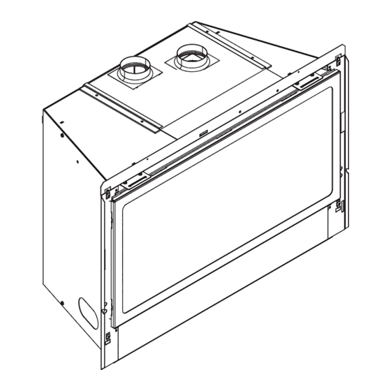
Page 11: Installing Vent Pipe And Appliance
INLET AIR STARTING COLLAR EXHAUST LOCKING TAB VENT PIPE STARTING COLLAR BRACKET EXHAUST STARTING COLLAR INLET AIR VENT PIPE INLET AIR STARTING COLLAR STARTING COLLAR BRACKET EXHAUST STARTING COLLAR Figure 7.1 Heat & Glo • Cosmo-SXT-IPI, Cosmo-GXT-IPI • 2203-900 Rev. E • 1/10... -
Page 12: Placing, Securing And Leveling The Appliance
• Attach surround. Follow instructions accompanying surround. • Push insert so that surround becomes tight against face of fi replace. Heat & Glo • Cosmo-SXT-IPI, Cosmo-GXT-IPI • 2203-900 Rev. E • 1/10... -
Page 13: Installing Adaptor And Termination Cap
3 screws. Connect both the LINK-ZC-ADPB to Class VENT PIPE achieve full 30’ A Pipe and the termination cap to the LINK-ZC-ADPB length. with the self tapping screws provided. Figure 7.4 Heat & Glo • Cosmo-SXT-IPI, Cosmo-GXT-IPI • 2203-900 Rev. E • 1/10... -
Page 14: Gas Information
Natural Gas Propane Minimum inlet pressure 5.0 in. w.c. 11.0 in. w.c. Maximum inlet pressure 10.0 in. w.c. 13.0 in. w.c. Manifold pressure 3.5 in. w.c. 10.0 in. w.c. Heat & Glo • Cosmo-SXT-IPI, Cosmo-GXT-IPI • 2203-900 Rev. E • 1/10... - Page 15 Do NOT change the valve settings. • This valve has been preset at the factory. • Changing valve settings may result in fi re hazard or bodily injury. Heat & Glo • Cosmo-SXT-IPI, Cosmo-GXT-IPI • 2203-900 Rev. E • 1/10...
-
Page 16: Electrical Information
• If desired, an additional wall switch or thermostat may be added to system as shown in Figure 9.1). Follow directions included with the optional wall switch. Heat & Glo • Cosmo-SXT-IPI, Cosmo-GXT-IPI • 2203-900 Rev. E • 1/10... -
Page 17: Junction Box Installation
Wiring errors can cause improper and dangerous operation. Verify proper operation after servicing. WARNING Shock hazard. • Replace damaged wire with type 105º C rated wire. • Wire must have high temperature insulation. Heat & Glo • Cosmo-SXT-IPI, Cosmo-GXT-IPI • 2203-900 Rev. E • 1/10... - Page 18 SENSOR SWITCH IT MUST BE REPLACED WITH TYPE C RATED WIRE. SPEED CONTROL (RHEOSTAT) BEND GROUND WIRE UP TABS (ATTACH TO ANY METAL SURFACE) Figure 9.3 Fan/Rheostat Wire Diagram Heat & Glo • Cosmo-SXT-IPI, Cosmo-GXT-IPI • 2203-900 Rev. E • 1/10...
-
Page 19: Finishing
12 in. MAX. EXHAUST VENT PIPE VENT PIPE MANTEL 12 in. MIN. MEASUREMENTS FROM TOP EDGE OF UNIT Figure 10.1 Clearances to Mantels or other Combustibles above Appliance Heat & Glo • Cosmo-SXT-IPI, Cosmo-GXT-IPI • 2203-900 Rev. E • 1/10... -
Page 20: Appliance Setup
• Do NOT use any media other than the glass media supplied with this fi replace. Figure 11.1 Placement of Glass Panels Fireplace will not function properly. Delayed ignition may occur. Heat & Glo • Cosmo-SXT-IPI, Cosmo-GXT-IPI • 2203-900 Rev. E • 1/10... -
Page 21: Glass Assembly
Tilt glass assembly toward fi replace and slide glass as- sembly upward to engage top latches. Verify top latches are fully engaged and then fasten the two bottom latches. Heat & Glo • Cosmo-SXT-IPI, Cosmo-GXT-IPI • 2203-900 Rev. E • 1/10... -
Page 22: Operating Instructions
• Only use glass door certifi ed for use with appliance. • Glass replacement should be done by qualifi ed technician. Heat & Glo • Cosmo-SXT-IPI, Cosmo-GXT-IPI • 2203-900 Rev. E • 1/10... -
Page 23: Lighting Appliance
For additional information on operating your Hearth & Home Technologies fi replace, please refer to www.fi replaces.com. Final inspection by Heat & Glo • Cosmo-SXT-IPI, Cosmo-GXT-IPI • 2203-900 Rev. E • 1/10... -
Page 24: Check Pilot Flame Appearance
This will help avoid setting off smoke detectors, and help eliminate any odors associated with the appliance’s initial burning. Heat & Glo • Cosmo-SXT-IPI, Cosmo-GXT-IPI • 2203-900 Rev. E • 1/10... -
Page 25: Frequently Asked Questions
Is it normal to see the pilot fl ame burn turned off. Some optional control systems available with IPI models may allow pilot fl ame to continually? remain lit. Heat & Glo • Cosmo-SXT-IPI, Cosmo-GXT-IPI • 2203-900 Rev. E • 1/10... -
Page 26: Troubleshooting
Verify module is securely grounded to metal chassis of appliance. D. Module voltage output / Valve/Pilot Verify battery voltage is at least 2.7 volts. Replace batteries if volt- solenoid ohms readings. age is below 2.7. Heat & Glo • Cosmo-SXT-IPI, Cosmo-GXT-IPI • 2203-900 Rev. E • 1/10... - Page 27 ON position. If there is no spark at “I” terminal module must be replaced. If there is a spark at “I” terminal, module is fi ne. Heat & Glo • Cosmo-SXT-IPI, Cosmo-GXT-IPI • 2203-900 Rev. E • 1/10...
-
Page 28: Maintaining And Servicing Appliance
• Glass • Air passageways, grilles, control compartment • Burner, burner ports Risk of: • Fire • Delayed ignition or explosion • Exposure to combustion fumes • Odors Heat & Glo • Cosmo-SXT-IPI, Cosmo-GXT-IPI • 2203-900 Rev. E • 1/10... - Page 29 1. Verify operation of remote. 2. Replace batteries in remote transmitters and battery-powered receivers. 3. Verify batteries have been removed from battery back-up IPI systems to prevent premature battery failure or leaking. Heat & Glo • Cosmo-SXT-IPI, Cosmo-GXT-IPI • 2203-900 Rev. E • 1/10...
-
Page 30: Reference Materials
13-23/32 14-3/4 12-7/16 2-17/32 2-17/32 22-23/32 5-9/32 5-9/32 22-3/4 20-1/4 8-29/32 8-29/32 23-11/16 21-5/32 14-11/16 14-11/16 8-7/16 REF 8-7/16 REF 2-19/32 2-19/32 6-1/16 6-1/16 Figure 15.1 Appliance Dimensions Heat & Glo • Cosmo-SXT-IPI, Cosmo-GXT-IPI • 2203-900 Rev. E • 1/10... -
Page 31: Vent Kits Components
FLEX3-30: One 3 inch fl exible liner expands to 30 feet. FLEX3-CNCT FLEX-CNCT: Connector kit - 3 inch liner to 3 inch liner, one connector per kit. Figure 15.3 Direct Vent Flex Liner Accessory Kits Heat & Glo • Cosmo-SXT-IPI, Cosmo-GXT-IPI • 2203-900 Rev. E • 1/10... -
Page 32: Service Parts
D. Limited Lifetime Warranty Heat & Glo • Cosmo-SXT-IPI, Cosmo-GXT-IPI • 2203-900 Rev. E • 1/10... - Page 33 Heat & Glo • Cosmo-SXT-IPI, Cosmo-GXT-IPI • 2203-900 Rev. E • 1/10...
-
Page 34: Contact Information
6774802, 6796302, 6840261, 6848441, 6863064, 6866205, 6869278, 6875012, 6880275, 6908039, 6919884, D320652, D445174, D462436; (Canada) 1297749, 2195264, 2225408, 2313972; (Australia) 780250, 780403, 1418504 or other U.S. and foreign patents pending. Printed in U.S.A. - Copyright 2010 Heat & Glo • Cosmo-SXT-IPI, Cosmo-GXT-IPI • 2203-900 Rev. E • 1/10...
Need help?
Do you have a question about the Cosmo-SXT-IPI and is the answer not in the manual?
Questions and answers