Table of Contents
Advertisement
Models:
COSMO-I30-C
COSMO-I35-C
• Important operating
a n d m a i n t e n a n c e
instructions included.
WARNING: If the information in these
instructions is not followed exactly, a fi re
or explosion may result causing property
damage, personal injury, or death.
• DO NOT store or use gasoline or other fl am-
mable vapors and liquids in the vicinity of this
or any other appliance.
• What to do if you smell gas
- DO NOT try to light any appliance.
- DO NOT touch any electrical switch. DO
NOT use any phone in your building.
- Immediately call your gas supplier from a
neighbor's phone. Follow the gas suppli-
er's instructions.
- If you cannot reach your gas supplier, call
the fi re department.
• Installation and service must be performed
by a qualifi ed installer, service agency, or the
gas supplier.
In the Commonwealth of Massachusetts installation must be
performed by a licensed plumber or gas fi tter.
A CO detector shall be installed in the room where the appliance
in installed.
Installation and service of this appliance should be
performed by qualifi ed personnel. Hearth & Home
Technologies suggests NFI certifi ed or factory trained
professionals, or technicians supervised by an NFI
certifi ed professional.
NOTICE
DO NOT DISCARD THIS MANUAL
• Read, understand and follow
these instructions for safe
installation and operation.
Heat & Glo • Cosmo-I30-C, Cosmo-I35-C • 2239-901 Rev. o • 6/14
Owner's Manual
Installation and Operation
• Leave this manual with
party responsible for use
and operation.
WARNING
HOT GLASS WILL
CAUSE BURNS.
DO NOT TOUCH GLASS
UNTIL COOLED.
NEVER ALLOW CHILDREN
TO TOUCH GLASS.
A barrier designed to reduce the risk of burns
from the hot viewing glass is provided with this
appliance and shall be installed.
This appliance may be installed as an OEM
installation in manufactured home (USA
only) or mobile home and must be installed
in accordance with the manufacturer's
instructions and the Manufactured Home
Construction and Safety Standard, Title 24
CFR, Part 3280 in the United States, or the
Standard for Installation in Mobile Homes,
CAN/CSA Z240 MH Series, in Canada.
This appliance is only for use with the type(s)
of gas indicated on the rating plate. This
appliance is not convertible for use with other
gases, unless a certifi ed kit is used.
Pour demander un exemplaire en français de ce Manuel
du propriétaire, visitez www.heatnglo.com/translations.
1
Advertisement
Table of Contents

Related Manuals for Heat & Glo COSMO-I30-C


Summary of Contents for Heat & Glo COSMO-I30-C
- Page 1 Technologies suggests NFI certifi ed or factory trained professionals, or technicians supervised by an NFI Pour demander un exemplaire en français de ce Manuel certifi ed professional. du propriétaire, visitez www.heatnglo.com/translations. Heat & Glo • Cosmo-I30-C, Cosmo-I35-C • 2239-901 Rev. o • 6/14...
-
Page 2: Congratulations
00,000 00,000 00,000 00,000 MIN. MIN. INPUT INPUT BTUH: BTUH: 00,000 00,000 00,000 00,000 Serial Serial XXXXXXXX XXXXXXXX ORIFICE ORIFICE SIZE: SIZE: #XXXXX #XXXXX #XXXXX #XXXXX (Serie): (Serie): Heat & Glo • Cosmo-I30-C, Cosmo-I35-C • 2239-901 Rev. o • 6/14... -
Page 3: Table Of Contents
B. Flue Damper........21 = Contains updated information. Heat & Glo • Cosmo-I30-C, Cosmo-I35-C • 2239-901 Rev. o • 6/14... -
Page 4: Limited Lifetime Warranty
3 years Firebox and heat exchanger Lifetime All replacement parts 90 Days beyond warranty period See conditions, exclusions, and limitations on next page. 4021-645F 02-18-13 Page 1 of 2 Heat & Glo • Cosmo-I30-C, Cosmo-I35-C • 2239-901 Rev. o • 6/14... - Page 5 THE EXTENT PROVIDED BY LAW, HHT MAKES NO EXPRESS WARRANTIES OTHER THAN THE WARRANTY SPECIFIED HEREIN. THE DURATION OF ANY IMPLIED WARRANTY IS LIMITED TO DURATION OF THE EXPRESSED WARRANTY SPECIFIED ABOVE. 4021-645F 02-18-13 Page 2 of 2 Heat & Glo • Cosmo-I30-C, Cosmo-I35-C • 2239-901 Rev. o • 6/14...
-
Page 6: Listing And Code Approvals
COSMO-I35-C (NG) CANADA 25,200 13,950 (2000-4500 FT) 23,000 13,500 (0-2000 FT) COSMO-I30-C (LP) CANADA 20,700 12,150 (2000-4500 FT) 27,500 14,500 (0-2000 FT) COSMO-I35-C (LP) CANADA 24,750 14,000 (2000-4500 FT) Heat & Glo • Cosmo-I30-C, Cosmo-I35-C • 2239-901 Rev. o • 6/14... -
Page 7: User Guide
• Keep remote controls out of reach of children. • Never leave children alone near a hot fi replace, whether operating or cooling down. • Teach children to NEVER touch the fi replace. Heat & Glo • Cosmo-I30-C, Cosmo-I35-C • 2239-901 Rev. o • 6/14... -
Page 8: Clear Space
Contact your dealer or Hearth & Home Technologies if the barrier is not present or help is needed to properly install one. For more information refer to the instructions supplied with your decorative door or front. Heat & Glo • Cosmo-I30-C, Cosmo-I35-C • 2239-901 Rev. o • 6/14... -
Page 9: Control Module Operation
• Wait fi ve (5) minutes to allow possible accumulated gas • An Intellifi re™ Plus ignition system is standard with this to clear. appliance. • Set the module selector switch to ON or REMOTE position. Heat & Glo • Cosmo-I30-C, Cosmo-I35-C • 2239-901 Rev. o • 6/14... -
Page 10: Lighting Instructions (Ipi)
For additional information on operating your Hearth & Home Technologies fi replace, please refer to www.fi replaces.com. Final inspection by Heat & Glo • Cosmo-I30-C, Cosmo-I35-C • 2239-901 Rev. o • 6/14... -
Page 11: After Appliance Is Lit
Is it normal to see the pilot fl ame burn turned off. Some optional control systems available with IPI models may allow pilot fl ame to continually? remain lit. Heat & Glo • Cosmo-I30-C, Cosmo-I35-C • 2239-901 Rev. o • 6/14... -
Page 12: Maintenance And Service
• Carefully set fi xed glass assembly in place on appliance. Hold glass in place with one hand and secure glass latches with the other hand. • Reinstall door or decorative front. Heat & Glo • Cosmo-I30-C, Cosmo-I35-C • 2239-901 Rev. o • 6/14... -
Page 13: Maintenance Tasks-Service Technician
• Confi rm there is no damage to glass or glass frame. Replace as necessary. • Verify that fi xed glass assembly is properly retained and attachment components are intact and not damaged. Replace as necessary. Heat & Glo • Cosmo-I30-C, Cosmo-I35-C • 2239-901 Rev. o • 6/14... -
Page 14: Burner Ignition And Operation
• Verify that there is not a short in fl ame sense circuit by checking continuity between pilot hood and fl ame sense rod. Replace pilot as necessary. (IPI only) Heat & Glo • Cosmo-I30-C, Cosmo-I35-C • 2239-901 Rev. o • 6/14... -
Page 15: Installer Guide
SECTION 5.B AND 11.A SURROUND OR FRONT NOT SHOWN SECTION 2.D AND 8.D. HEARTH EXTENSION GAS LINE (SECTION 9) ACCESS THROUGH EXISTING MASONRY OR WOODBURNING FIREPLACE Figure 4.1 Typical System Heat & Glo • Cosmo-I30-C, Cosmo-I35-C • 2239-901 Rev. o • 6/14... -
Page 16: Design And Installation Considerations
Safety glasses Level Reciprocating saw Manometer Noncorrosive leak check solution 1/2 - 3/4 inch length, #6 or #8 Self-drilling screws Caulking material (300º F minimum continuous exposure rating) Heat & Glo • Cosmo-I30-C, Cosmo-I35-C • 2239-901 Rev. o • 6/14... -
Page 17: Fireplace Size Requirements
The original fi replace may never be returned to solid fuel in this condition. The sidewalls and top structure of the fi rebox may not be altered with the exception of removable baffl es and dampers. Heat & Glo • Cosmo-I30-C, Cosmo-I35-C • 2239-901 Rev. o • 6/14... - Page 18 **Unit depth is measured to the back of the surround to give the depth needed for installation. In addition to these dimensions, also reference Clearances and Mantel Projections (Section 5.B). Figure 5.2 Fireplace Opening Heat & Glo • Cosmo-I30-C, Cosmo-I35-C • 2239-901 Rev. o • 6/14...
-
Page 19: Mantel And Wall Projections
fi rebox. Combustible facings must not extend behind the insert surround. For non-combustible material specifi cations refer to section 1.E. Figure 5.4 Mantel Clearances Heat & Glo • Cosmo-I30-C, Cosmo-I35-C • 2239-901 Rev. o • 6/14... -
Page 20: Termination Locations
Over 16/12 to 18/12 ..........7.0 Over 18/12 to 20/12 ..........7.5 Over 20/12 to 21/12 ..........8.0 * 3 foot minimum in snow regions Figure 6.1 Minimum Height From Roof To Lowest Discharge Opening Heat & Glo • Cosmo-I30-C, Cosmo-I35-C • 2239-901 Rev. o • 6/14... -
Page 21: Installation Preparation
• It is recommended that extra length of gas line be installed within the existing wood burner or masonry fi replace to allow removal of the insert for future servicing needs. Heat & Glo • Cosmo-I30-C, Cosmo-I35-C • 2239-901 Rev. o • 6/14... -
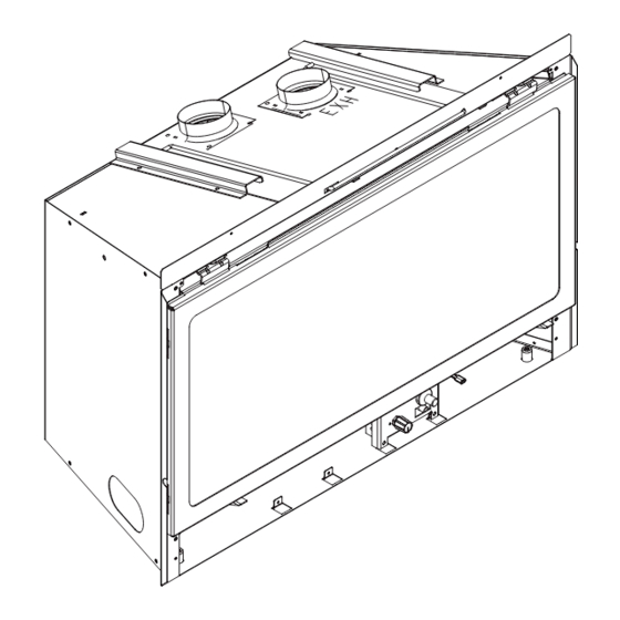
Page 22: Installing Vent Pipe And Appliance
INLET AIR STARTING COLLAR NOTE: TO ACHIEVE OPTIMUM PERFOR- MANCE OF INSERT, MINIMIZE OR AVOID BENDS IN EXHAUST VENT PIPE. STARTING COLLAR BRACKET EXHAUST STARTING COLLAR Figure 8.1 Heat & Glo • Cosmo-I30-C, Cosmo-I35-C • 2239-901 Rev. o • 6/14... -
Page 23: Placing, Securing And Leveling The Appliance
See Figure 5.1. • Position any excess fl exible vent pipe back up into chimney without sagging. Twist and push flex vent together to shorten. Figure 8.3 Heat & Glo • Cosmo-I30-C, Cosmo-I35-C • 2239-901 Rev. o • 6/14... -
Page 24: Remote Control
Auxiliary 300 module can only be placed in the control cavity to the right of the control panel. See Figure 8.4. AUXILIARY 300 MODULE Figure 8.4 Location of AUX300 for Remote Control Blower Function Heat & Glo • Cosmo-I30-C, Cosmo-I35-C • 2239-901 Rev. o • 6/14... -
Page 25: Installing Adaptor And Termination Cap
VENT PIPE VENT PIPE screws. Connect both the LINK-ZC-ADPB to Class A Pipe and the termination cap to the LINK-ZC-ADPB with the self tapping screws provided. Figure 8.7 Heat & Glo • Cosmo-I30-C, Cosmo-I35-C • 2239-901 Rev. o • 6/14... -
Page 26: Gas Information
fl exible gas connector are connected to the 1/2 inch (13 mm) control valve inlet. • If substituting for these components, please consult local codes for compliance. Heat & Glo • Cosmo-I30-C, Cosmo-I35-C • 2239-901 Rev. o • 6/14... -
Page 27: Electrical Information
ASSEMBLY (110V) BATTERY PACK 6V DC ORANGE GREEN ROCKER (PILOT) (MAIN) SWITCH BROWN WALL SWITCH OR REMOTE INSTALL EMC FILTER UNIT GROUND GROUND Figure 10.1 IPI Wiring Diagram Heat & Glo • Cosmo-I30-C, Cosmo-I35-C • 2239-901 Rev. o • 6/14... -
Page 28: Optional Accessories Requirements
PLUG INTO 120V EXISTING OUTLET DC REGULATOR RECEPTACLE VARIABLE SPEED CONTROL BLOWERS FUSE WIRE BLOWER TEMPERATURE RECEPTACLE ASSEMBLY SENSOR SWITCH FUSE WIRE ASSEMBLY Figure 10.2 Fan Wiring Diagram Heat & Glo • Cosmo-I30-C, Cosmo-I35-C • 2239-901 Rev. o • 6/14... -
Page 29: Fan Wiring With Remote
EXISTING OUTLET DC REGULATOR RECEPTICLE BLOWERS AUX 300 MODULE FUSE WIRE ASSEMBLY TO CONTROL MODULE FUSE WIRE ASSEMBLY BLOWER RECEPTICLE Figure 10.3 Wiring Diagram - Fan with RC200/RC300 Remote Heat & Glo • Cosmo-I30-C, Cosmo-I35-C • 2239-901 Rev. o • 6/14... -
Page 30: Finishing
Combustible facings must not extend behind the insert surround. For non-combustible material specifi cations refer to section 1.E. Figure 11.1 Clearances to Mantels or other Combustibles above Appliance Heat & Glo • Cosmo-I30-C, Cosmo-I35-C • 2239-901 Rev. o • 6/14... -
Page 31: Appliance Setup
Improperly placed glass rock Figure 12.1 Placement of Glass Panels media interfere with proper burner operation. RETAINING BRACKET SELF-DRILLING SCREW GLASS PANEL RETAINING TAB Figure 12.2 Bend Retaining Tab Down Heat & Glo • Cosmo-I30-C, Cosmo-I35-C • 2239-901 Rev. o • 6/14... -
Page 32: Fixed Glass Assembly
Verify top latches are fully engaged and then fasten the two bottom latches. COSMO-I30-C 1/8 in. 1/4 in. COSMO-I35-C 1/8 in. 1/4 in. Figure 12.3 Fixed Glass Assembly Heat & Glo • Cosmo-I30-C, Cosmo-I35-C • 2239-901 Rev. o • 6/14... -
Page 33: Troubleshooting
D. Pilot valve solenoid Verify that 1.5 to 1.8 VDC is supplied to pilot solenoid from module. If below 1.5 volts, replace module. If 1.5 volts or greater, replace valve. Heat & Glo • Cosmo-I30-C, Cosmo-I35-C • 2239-901 Rev. o • 6/14... - Page 34 fl ame sensing rod. Verify continuity with a multi-meter with ohms set at lowest range. Replace pilot if any damage is detected. Heat & Glo • Cosmo-I30-C, Cosmo-I35-C • 2239-901 Rev. o • 6/14...
-
Page 35: Reference Materials
10-1/2 9-1/2 4-11/16 4-9/16 *Note: Location G on Figure 14.1 is measuring the appliance depth, for installation depth reference Location G on Figure 5.1. Figure 14.1 Appliance Dimensions Heat & Glo • Cosmo-I30-C, Cosmo-I35-C • 2239-901 Rev. o • 6/14... -
Page 36: Vent Kits Components
FLEX3-30: One 3 inch fl exible liner expands to 30 feet. FLEX-CNCT: Connector kit - 3 inch liner to 3 inch liner, one connector per kit. Heat & Glo • Cosmo-I30-C, Cosmo-I35-C • 2239-901 Rev. o • 6/14... -
Page 37: Service Parts
On/Off Rheostat 2206-800 Blower GFK-210-C Wire Assembly 2206-068 Power cord Assembly 2201-017 Fuse Wire Assembly Qty 2 req 2206-085 Additional service part numbers appear on following page. 6/14 Heat & Glo • Cosmo-I30-C, Cosmo-I35-C • 2239-901 Rev. o • 6/14... - Page 38 On/Off Rheostat 2206-800 Blower GFK-210-C Wire Assembly 2206-068 2201-017 Power cord Assembly Qty 2 req 2206-085 Fuse Wire Assembly Additional service part numbers appear on following page. 6/14 Heat & Glo • Cosmo-I30-C, Cosmo-I35-C • 2239-901 Rev. o • 6/14...
- Page 39 046-018A **Fuse for battery pack can be sourced locally, not a warranty item. Specs are 250v, 1A fuse, 3/4” long Additional service part numbers appear on following page. Heat & Glo • Cosmo-I30-C, Cosmo-I35-C • 2239-901 Rev. o • 6/14...
- Page 40 Glass Refractory, Right 2238-202 Conversion Kit NG NGK-COSMOI35-C Conversion Kit LP LPK-COSMOI35-C Pilot Orifi ce NG 593-528 Pilot Orifi ce LP 593-527 Regulator NG NGK-DXV-50 Regulator LP LPK-DXV-50 Heat & Glo • Cosmo-I30-C, Cosmo-I35-C • 2239-901 Rev. o • 6/14...
-
Page 41: Contact Information
5890485, 5941237, 6006743, 6019099, 6053165, 6145502, 6374822, 6484712, 6601579, 6769426, 6863064, 7077122, 7098269, 7258116, 7470729, 8147240 or other U.S. and foreign patents pending. 2000-945B Printed in U.S.A. - Copyright 2014 Heat & Glo • Cosmo-I30-C, Cosmo-I35-C • 2239-901 Rev. o • 6/14...
Need help?
Do you have a question about the COSMO-I30-C and is the answer not in the manual?
Questions and answers