Table of Contents
Advertisement
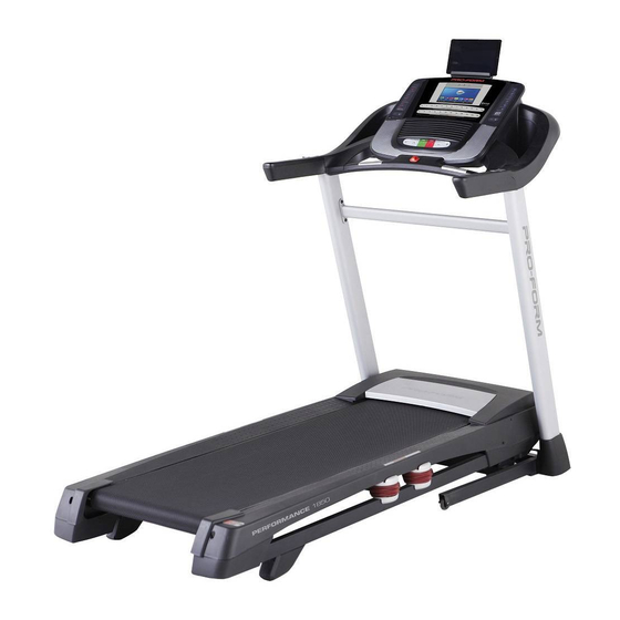
Model No. PETL14715.0
Serial No.
Write the serial number in the space
above for reference.
Serial Number
Decal
CUSTOMER SERVICE
UNITED KINGDOM
Call: 0330 123 1045
From Ireland: 053 92 36102
Website: www.iconsupport.eu
E-mail: csuk@iconeurope.com
Write:
ICON Health & Fitness, Ltd.
Unit 1D, The Gateway
Fryers Way, Silkwood Park
OSSETT
WF5 9TJ
UNITED KINGDOM
AUSTRALIA
Call: 1800 993 770
E-mail: australiacc@iconfitness.com
Write:
ICON Health & Fitness
PO Box 635
WINSTON HILLS NSW 2153
AUSTRALIA
CAUTION
Read all precautions and instruc-
tions in this manual before using
this equipment. Save this manual
for future reference.
USER'S MANUAL
www.iconeurope.com
Advertisement
Table of Contents

Subscribe to Our Youtube Channel
Related Manuals for Pro-Form performance 1850 PETL14715.0


Summary of Contents for Pro-Form performance 1850 PETL14715.0
- Page 1 Model No. PETL14715.0 Serial No. USER’S MANUAL Write the serial number in the space above for reference. Serial Number Decal CUSTOMER SERVICE UNITED KINGDOM Call: 0330 123 1045 From Ireland: 053 92 36102 Website: www.iconsupport.eu E-mail: csuk@iconeurope.com Write: ICON Health & Fitness, Ltd. Unit 1D, The Gateway Fryers Way, Silkwood Park OSSETT...
-
Page 2: Table Of Contents
TABLE OF CONTENTS WARNING DECAL PLACEMENT ............. . .2 IMPORTANT PRECAUTIONS . -
Page 3: Important Precautions
IMPORTANT PRECAUTIONS WARNING: To reduce the risk of burns, fire, electric shock, or injury to persons, read all important precautions and instructions in this manual and all warnings on your treadmill before using your treadmill. ICON assumes no responsibility for personal injury or property damage sus- tained by or through the use of this product. - Page 4 22. Never leave the treadmill unattended while 26. Inspect and properly tighten all parts of the it is running. Always remove the key, press treadmill regularly. the power switch into the off position (see DANGER: the drawing on page 5 for the location of the Always unplug the power power switch), and unplug the power cord cord immediately after use, before clean-...
-
Page 5: Before You Begin
BEFORE YOU BEGIN Thank you for selecting the revolutionary reading this manual, please see the front cover of this PROFORM PERFORMANCE 1850 treadmill. The manual. To help us assist you, please note the product ® PERFORMANCE 1850 treadmill offers an impres- model number and serial number before contacting us. -
Page 6: Part Identification Chart
PART IDENTIFICATION CHART Use the drawings below to identify small parts used for assembly. The number in parentheses below each draw- ing is the key number of the part, from the PART LIST near the end of this manual. The number following the key number is the quantity used for assembly. -
Page 7: Assembly
ASSEMBLY • Assembly requires two persons. • Left parts are marked “L” or “Left” and right parts are marked “R” or “Right.” • Place all parts in a cleared area and remove the packing materials. Do not dispose of the packing •... - Page 8 2. Make sure that the power cord is unplugged. Wire Press a Base Cap (74) into each side of the Base (94). Next, remove the tie securing the Upright Wire (81) to the front of the Base (94). Identify the Right Upright (90). Have a second person hold the Right Upright near the Base (94).
- Page 9 4. Insert a Wheel Spacer (63) into a Front Wheel (62). Hold the Front Wheel inside the bottom of the Right Upright (90), and insert a 3/8" x 4" Screw (7) with a 3/8" Star Washer (13) into the Right Upright and the Front Wheel. Repeat this step on the left side of the tread- mill (not shown).
-
Page 10: 3/4" Screws (4
6. Remove and save the four indicated 5/16" x 3/4" Screws (4). Identify the Left and Right Base Covers (82, 83). Slide the Left Base Cover onto the Left Upright (89), and slide the Right Base Cover onto the Right Upright (90). Do not press the Base Covers into place yet. -
Page 11: 3/4" Screws (4
8. Insert the Upright Wire (81) into the bottom of the right handrail assembly (E) and out of the front as shown. Attach the right handrail assembly (E) to the Right Upright (90) with two 5/16" x 2 1/2" Screws (28) and two 5/16"... - Page 12 10. Identify the Right and Left Trays (27, 36). Attach the Trays (27, 36) to the Console Base (64) with eight #8 x 1/2" Screws (1); do not overtighten the Screws. Reattach the Console Frame (18) with the six #8 x 3/4"...
-
Page 13: 3/4" Screws (4
12. Hold the console assembly (H) near the Pulse Crossbar (93). Connect the ground wire from the console assembly to the Console Ground Wire (58) on the Pulse Crossbar. Next, set the console assembly (H) on the brack- ets on the Handrails (86); do not pinch any wires. - Page 14 15. Insert the Upright Wire (81) and the handrail wire (G) through the two indicated looped ties on the console assembly (H). See the inset drawing. Connect the Upright Wire (81) and the handrail wire (G) to the console wires. The connectors should slide Ties together easily and snap into place.
-
Page 15: 3/4" Screws (4
17. Firmly tighten the six 3/8" x 4" Screws (7) (only one side is shown). Then, press the Left Base Cover (82) and the Right Base Cover (83) onto the Base (94). 18. Note: If the treadmill is assembled on a smooth surface, it may roll forward during this step. - Page 16 19. Remove the 5/16" Nut (12) and the 5/16" x 1 3/4" Bolt (6) from the bracket on the Base (94). Next, orient the Storage Latch (53) as shown. Attach the lower end of the Storage Latch (53) to the bracket on the Base (94) with the 5/16" x 1 3/4"...
- Page 17 21. Attach the Tablet Holder (88) to the back of the console assembly (H) with four #8 x 1/2" Machine Screws (8); start all four Machine Screws, and then tighten them. Do not over- tighten the Machine Screws. 22. Make sure that all parts are properly tightened before you use the treadmill. If there are sheets of plastic on the treadmill decals, remove the plastic.
-
Page 18: The Chest Heart Rate Monitor
THE CHEST HEART RATE MONITOR HOW TO PUT ON THE HEART RATE MONITOR • Store the heart rate monitor in a warm, dry place. Do not store the heart rate monitor in a plastic bag or If the heart rate monitor looks like the one shown other container that may trap moisture. -
Page 19: How To Use The Treadmill
HOW TO USE THE TREADMILL HOW TO PLUG IN THE POWER CORD Follow the steps below to plug in the power cord. This product must be earthed. If it should malfunc- 1. Plug the indicated end of the power cord into the tion or break down, earthing provides a path of least socket on the treadmill. - Page 20 CONSOLE DIAGRAM MAKE YOUR FITNESS GOALS A REALITY WITH FEATURES OF THE CONSOLE IFIT.COM The advanced treadmill console offers an array of fea- With your new iFit-enabled fitness equipment, you can tures designed to make your workouts more effective use an array of features on iFit.com to make your fit- and enjoyable.
- Page 21 HOW TO TURN ON THE POWER HOW TO USE THE TOUCH SCREEN IMPORTANT: If the treadmill has been exposed to The console features a tablet with a full-color touch cold temperatures, allow it to warm to room tem- screen. The following information will help you become perature before you turn on the power.
- Page 22 HOW TO SET UP THE CONSOLE To use the equipment settings mode, see page 28. To use the sound system, see page 29. Before using the treadmill for the first time, set up the To use the Internet browser, see page 30. To use the maintenance mode, see page 30.
- Page 23 If you press one of the Quick Speed buttons, the As you walk or run on the treadmill, the screen can walking belt will gradually change speed until it show the following workout information: reaches the selected speed setting. • The incline level of the treadmill To stop the walking belt, press the Stop button.
- Page 24 6. Measure your heart rate if desired. 8. When you are finished exercising, remove the key from the console. Note: If you use the handgrip heart rate moni- tor and the chest heart rate monitor at the same Step onto the walking platform and touch the home time, the console will not display your heart button or the back button on the screen or press rate accurately.
- Page 25 Note: The calorie goal is an estimate of the Each workout is divided into several segments. One speed setting and one incline setting are number of calories that you will burn during programmed for each segment. Note: The same the workout. The actual number of calories that you burn will depend on various factors speed setting and/or incline setting may be pro- such as your weight.
- Page 26 7. Turn on the fan if desired. To set a calorie, time, distance, or See step 7 on page 24. pace goal, 8. When you are finished exercising, remove the touch the Calories, Time, key from the console. Distance, or Pace button.
- Page 27 8. Turn on the fan if desired. To compete in a race that you have previously scheduled, touch the Compete button. To view your Workout History, touch the Track button. Note: See step 7 on page 24. You can also press one of the iFit buttons on the 9.
- Page 28 5. Start the workout. 4. Select the unit of measurement. Touch the Start Workout button on the screen to Touch the US/Metric button to view the selected start the workout. A moment after you touch the unit of measurement. Change the unit of measure- button, the walking belt will begin to move.
- Page 29 9. Enable or disable the street view. 12. Set a safety screen timeout. During some workouts, the screen may show a The console features an automatic screen reset; if map. To enable or disable the street view feature of no buttons are touched or pressed and the walking the maps, first touch the Street View button.
- Page 30 HOW TO USE THE INTERNET BROWSER HOW TO USE THE MAINTENANCE MODE Note: To use the browser, you must have access to a 1. Select the settings main menu. wireless network including an 802.11b/g/n router with SSID broadcast enabled (hidden networks are not See step 1 on page 28.
- Page 31 4. Calibrate the incline system of the treadmill. HOW TO USE THE WIRELESS NETWORK MODE Touch the Calibrate Incline button. Then, touch the The console features a wireless network mode that Begin button to calibrate the incline system. The allows you to set up a wireless network connection. treadmill will automatically rise to the maximum incline level, lower to the minimum incline level, 1.
- Page 32 Note: If you have questions after following An information box will ask if you want to connect to the wireless network. Touch the Connect button these instructions, go to support.iFit.com for to connect to the network or touch the Cancel but- assistance.
-
Page 33: How To Fold And Move The Treadmill
HOW TO FOLD AND MOVE THE TREADMILL HOW TO FOLD THE TREADMILL HOW TO MOVE THE TREADMILL To avoid damaging the treadmill, adjust the incline Before moving the treadmill, fold it as described at the to zero before you fold the treadmill. Then, remove left. -
Page 34: Maintenance And Troubleshooting
MAINTENANCE AND TROUBLESHOOTING MAINTENANCE SYMPTOM: The power turns off during use Regularly clean the treadmill and keep the walking a. Check the power switch (see drawing c at the left). belt clean and dry. First, press the power switch into If the switch has tripped, wait for five minutes and the off position and unplug the power cord. - Page 35 SYMPTOM: The treadmill will not connect to a wire- Locate the Reed Switch (52) and the Magnet (50) on the left side of the Pulley (49). Turn the Pulley less network until the Magnet is aligned with the Reed Switch. Make sure that the gap between the Magnet and a.
- Page 36 SYMPTOM: The walking belt slips when walked on c. Your treadmill features a walking belt coated with high-performance lubricant. IMPORTANT: Never apply silicone spray or other substances to a. First, remove the key and UNPLUG THE POWER the walking belt or the walking platform unless CORD.
-
Page 37: Exercise Guidelines
EXERCISE GUIDELINES Burning Fat—To burn fat effectively, you must exer- WARNING: cise at a low intensity level for a sustained period of Before beginning this time. During the first few minutes of exercise, your or any exercise program, consult your physi- body uses carbohydrate calories for energy. -
Page 38: Part List
PART LIST Model No. PETL14715.0 R0315A Key No. Qty. Description Key No. Qty. Description #8 x 1/2" Screw Reed Switch Clip #8 x 3/4" Screw Reed Switch 5/16" x 2 1/4" Bolt Storage Latch 5/16" x 3/4" Screw Drive Motor #10 Star Washer Motor Belt 5/16"... - Page 39 Key No. Qty. Description Key No. Qty. Description #8 x 3/4" Washer Head Screw Receptacle #8 x 3/4" Truss Head Screw Motor Bushing Left Rear Cap #8 x 3/4" Machine Screw Right Rear Cap #8 Nut 1/4" Nut Electronics Bracket Controller Clamp Filter #8 x 1 3/4"...
-
Page 40: Exploded Drawing
EXPLODED DRAWING A Model No. PETL14715.0 R0315A... - Page 41 EXPLODED DRAWING B Model No. PETL14715.0 R0315A...
- Page 42 EXPLODED DRAWING C Model No. PETL14715.0 R0315A...
- Page 43 EXPLODED DRAWING D Model No. PETL14715.0 R0315A...
-
Page 44: Ordering Replacement Parts
ORDERING REPLACEMENT PARTS To order replacement parts, please see the front cover of this manual. To help us assist you, be prepared to provide the following information when contacting us: • the model number and serial number of the product (see the front cover of this manual) •...
Need help?
Do you have a question about the performance 1850 PETL14715.0 and is the answer not in the manual?
Questions and answers