Table of Contents
Advertisement
Quick Links
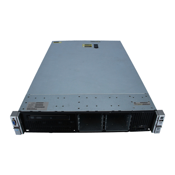
HP ProLiant DL380e Gen8 Server
Maintenance and Service Guide
Abstract
This guide describes identification and maintenance procedures, diagnostic tools, specifications and requirements for hardware components and
software. This guide is for an experienced service technician. HP assumes that you are qualified in the servicing of computer equipment, trained in
recognizing hazards in products, and are familiar with weight and stability precautions.
Part Number: 676140-006
May 2015
Edition: 6
Advertisement
Table of Contents

Related Manuals for HP ProLiant DL380e Gen8


Summary of Contents for HP ProLiant DL380e Gen8
- Page 1 This guide describes identification and maintenance procedures, diagnostic tools, specifications and requirements for hardware components and software. This guide is for an experienced service technician. HP assumes that you are qualified in the servicing of computer equipment, trained in recognizing hazards in products, and are familiar with weight and stability precautions.
- Page 2 © Copyright 2012, 2015 Hewlett-Packard Development Company, L.P. The information contained herein is subject to change without notice. The only warranties for HP products and services are set forth in the express warranty statements accompanying such products and services. Nothing herein should be construed as constituting an additional warranty. HP shall not be liable for technical or editorial errors or omissions contained herein.
-
Page 3: Table Of Contents
Contents Customer self repair ........................6 Parts only warranty service ..........................6 Illustrated parts catalog ....................... 16 Mechanical components ..........................16 System components ............................ 20 Removal and replacement procedures ................... 28 Required tools ............................28 Safety considerations ..........................28 Preventing electrostatic discharge ...................... 28 Symbols on equipment ........................ - Page 4 Install the spare system board ......................71 Re-entering the server serial number and product ID ................77 Reactivate the HP Smart Array SAS license key ................... 78 Secondary PCI riser cage blank ........................79 LFF rear drive cage blank ..........................80 HP Trusted Platform Module.........................
- Page 5 HP 750 W CS Platinum Plus Hot-plug Power Supply (94% efficiency) ..........121 HP 750 W CS Titanium Hot-plug Power Supply (96% efficiency) ............121 HP 750 W CS -48 V DC Hot-plug Power Supply (94% efficiency) ............122 HP 1200 W CS Platinum Plus Hot-plug Power Supply (94% efficiency) ..........123 Hot-plug power supply calculations ......................
-
Page 6: Customer Self Repair
HP specifies in the materials shipped with a replacement CSR part whether a defective part must be returned to HP. In cases where it is required to return the defective part to HP, you must ship the defective part back to HP within a defined period of time, normally five (5) business days. The defective part must be returned with the associated documentation in the provided shipping material. - Page 7 HP sono realizzati con numerosi componenti che possono essere riparati direttamente dal cliente (CSR, Customer Self Repair). Se in fase di diagnostica HP (o un centro di servizi o di assistenza HP) identifica il guasto come riparabile mediante un ricambio CSR, HP lo spedirà direttamente al cliente per la sostituzione.
- Page 8 La mancata restituzione del componente può comportare la fatturazione del ricambio da parte di HP. Nel caso di riparazione da parte del cliente, HP sostiene tutte le spese di spedizione e resa e sceglie il corriere/vettore da utilizzare.
- Page 9 Si, durante la fase de diagnóstico, HP (o los proveedores o socios de servicio de HP) identifica que una reparación puede llevarse a cabo mediante el uso de un componente CSR, HP le enviará dicho componente directamente para que realice su sustitución. Los componentes CSR se clasifican en dos categorías:...
- Page 10 HP podrá cobrarle por el de sustitución. En el caso de todas sustituciones que lleve a cabo el cliente, HP se hará cargo de todos los gastos de envío y devolución de componentes y escogerá la empresa de transporte que se utilice para dicho servicio.
- Page 11 Opcional – Peças cujo reparo feito pelo cliente é opcional. Essas peças também são projetadas para o reparo feito pelo cliente. No entanto, se desejar que a HP as substitua, pode haver ou não a cobrança de taxa adicional, dependendo do tipo de serviço de garantia destinado ao produto.
- Page 12 No caso desse serviço, a substituição de peças CSR é obrigatória. Se desejar que a HP substitua essas peças, serão cobradas as despesas de transporte e mão-de-obra do serviço. Customer self repair 12...
- Page 13 Customer self repair 13...
- Page 14 Customer self repair 14...
- Page 15 Customer self repair 15...
-
Page 16: Illustrated Parts Catalog
Illustrated parts catalog Mechanical components HP continually improves and changes product parts. For complete and current supported parts information, see the HP PartSurfer website (http://partsurfer.hp.com). Item Description Spare part Customer self number repair (on page 6) Secondary PCI riser cage... - Page 17 Optional—Parts for which customer self repair is optional. These parts are also designed for customer self repair. If, however, you require that HP replace them for you, there may or may not be additional charges, depending on the type of warranty service designated for your product.
- Page 18 Optional: Opcional—Peças cujo reparo feito pelo cliente é opcional. Essas peças também são projetadas para o reparo feito pelo cliente. No entanto, se desejar que a HP as substitua, pode haver ou não a cobrança de taxa adicional, dependendo do tipo de serviço de garantia destinado ao produto.
- Page 19 Illustrated parts catalog 19...
-
Page 20: System Components
System components HP continually improves and changes product parts. For complete and current supported parts information, see the HP PartSurfer website (http://partsurfer.hp.com). Item Description Spare part Customer self number repair (on page 6) PCIe riser board options — — a) PCIe low-profile riser board... - Page 21 Item Description Spare part Customer self number repair (on page 6) System board assembly for Intel Xeon E5-2400 and E5-2400 732145-001 Optional v2 processors a) System board with subpan* — — b) System board tray* — — c) PSU air baffle* —...
- Page 22 Item Description Spare part Customer self number repair (on page 6) q) 3-TB MDL hard drive* 739710-001 Mandatory r) 4-TB MDL hard drive* 738352-001 Mandatory SFF drive cage assemblies — — a) 8-bay SFF drive cage assembly 684887-001 Mandatory b) 25-bay SFF drive cage with backplane* 687961-001 Mandatory c) 2-bay SFF rear drive cage*...
- Page 23 Slimline 8x DVD+R/RW drive* 652295-001 Mandatory Power supplies — — a) HP 460 W CS Gold Hot-plug Power Supply (92% efficiency) 511777-001 Mandatory b) HP 460 W CS Platinum Hot plug Power Supply (94% 742515-001 Mandatory efficiency)* c) HP 460 W CS Platinum Plus Hot Plug Power Supply...
- Page 24 Item Description Spare part Customer self number repair (on page 6) i) 4 GB, dual-rank, x8 PC3L-12800E-11* 715280-001 Mandatory j) 8 GB, single-rank x4 PC3-12800R-11* 664691-001 Mandatory k) 8 GB, single-rank, x4 PC3L-12800R-11* 735302-001 Mandatory l) 8 GB, dual-rank x4 PC3-12800R-11* 698807-001 Mandatory m) 8 GB, dual-rank x4 PC3L-10600R-9*...
- Page 25 505836-001 * Not shown ** All processors in this HP ProLiant server must have the same cache size, speed, number of cores, and rated maximum power consumption. † The HP Dynamic Smart Array B320i controller embedded in this riser board option requires an HP Smart Array SAS License Key to support SAS drives.
- Page 26 Optional: Opcional—Peças cujo reparo feito pelo cliente é opcional. Essas peças também são projetadas para o reparo feito pelo cliente. No entanto, se desejar que a HP as substitua, pode haver ou não a cobrança de taxa adicional, dependendo do tipo de serviço de garantia destinado ao produto.
- Page 27 No: Nenhuma—Algumas peças da HP não são projetadas para o reparo feito pelo cliente. A fim de cumprir a garantia do cliente, a HP exige que um técnico autorizado substitua a peça. Essas peças estão identificadas com a marca “No”...
-
Page 28: Removal And Replacement Procedures
T-25 Torx screwdriver (for screws located inside the front panel quick-release levers) • T-10/T-15 Torx screwdriver • HP Insight Diagnostics (on page 83) Safety considerations Before performing service procedures, review all the safety information. Preventing electrostatic discharge To prevent damaging the system, be aware of the precautions you need to follow when setting up the system or handling parts. -
Page 29: Server Warnings And Cautions
Get help to lift and stabilize the product during installation or removal, especially when the • product is not fastened to the rails. HP recommends that a minimum of two people are required for all rack server installations. A third person may be required to help align the server if the server is installed higher than chest level. -
Page 30: Rack Warnings
Extend the server from the rack (on page 32). If you are performing service procedures in an HP, Compaq branded, Telco, or third-party rack cabinet, you can use the locking feature of the rack rails to support the server and gain access to internal components. -
Page 31: Remove The Security Bezel (Optional)
Remove the security bezel (optional) To access the front panel components, unlock and then remove the security bezel. Power down the server Before powering down the server for any upgrade or maintenance procedures, perform a backup of critical server data and programs. WARNING: To reduce the risk of personal injury, electric shock, or damage to the equipment, remove the power cord to remove power from the server. -
Page 32: Extend The Server From The Rack
If using a friction rail system, to perform installations or maintenance that requires access panel • removal, remove the server from the rack. To extend the server from an HP, Compaq-branded, Telco, or third-party rack: Power down the server (on page 31). Remove all power: Disconnect each power cord from the power source. -
Page 33: Access The Product Rear Panel
For more information, see the documentation that ships with the rack mounting option. Connect the peripheral cables. Connect each power cord to the server. Connect each power cord to the power source. Access the product rear panel Opening the cable management arm IMPORTANT: The cable management arm is not supported with the friction rail kit. -
Page 34: Remove The Server From The Rack
Get help to lift and stabilize the product during installation or removal, especially when the product is not fastened to the rails. HP recommends that a minimum of two people are required for all rack server installations. A third person may be required to help align the server if the server is installed higher than chest level. -
Page 35: Hot-Plug Drive Blanks
Hot-plug drive blanks CAUTION: To prevent improper cooling and thermal damage, do not operate the server unless all bays are populated with either a component or a blank. To remove the component: If installed, remove the security bezel ("Remove the security bezel (optional)"... -
Page 36: Power Supply Blank
Remove the drive. To replace the component, reverse the removal procedure. Power supply blank CAUTION: To prevent improper cooling and thermal damage, do not operate the server unless all bays are populated with either a component or a blank. To remove the component: Access the rear panel ("Access the product rear panel"... -
Page 37: Access Panel
Disconnect each power cord from the server. If the server is using a DC power supply: Remove the safety cover. Remove the power ring tongues from the terminal block. Remove the ground (earthed) wire. WARNING: To reduce the risk of personal injury from hot surfaces, allow the power supply or power supply blank to cool before touching it. -
Page 38: Optical Drive Blank
To replace the component, reverse the removal procedure. Optical drive blank CAUTION: To prevent improper cooling and thermal damage, do not operate the chassis unless all bays are populated with a component or a blank. Remove the optical drive blank Retain the blank for future use. -
Page 39: Optical Drive Bracket
Remove the optical drive. Remove the optical drive bracket ("Optical drive bracket" on page 39). This bracket will be used to install the replacement optical drive. To replace the component, reverse the removal procedure. Optical drive bracket To remove the component: Power down the server (on page 31). -
Page 40: Optical Drive Cage
Remove the optical drive bracket. To replace the component, reverse the removal procedure. Optical drive cage To remove the component: Power down the server (on page 31). Remove all power: Disconnect each power cord from the power source. Disconnect each power cord from the server. Do one of the following: Extend the server from the rack (on page 32). - Page 41 Original release optical drive cage Redesigned optical drive cage Removal and replacement procedures 41...
-
Page 42: Air Baffle
To install the component: Install the new optical drive cage. Only the redesigned optical drive cage is available for spare installation. Perform steps 1-5 of the removal procedure in reverse sequence to complete the new optical drive cage installation. Air baffle To remove the component: CAUTION: For proper cooling, do not operate the server without the access panel, baffles,... -
Page 43: Front Drive Cage Assembly
Press and hold the release latches, and then remove the air baffle. To replace the component, reverse the removal procedure. Front drive cage assembly The drive cage assembly includes the drive cage with backplane and the front panel assembly. To remove the component: Power down the server (on page 31). -
Page 44: Hot-Plug Fan Blank And Module
Remove the drive cage assembly. To replace the component, reverse the removal procedure. Hot-plug fan blank and module To provide sufficient airflow to the system if a fan fails, the server supports redundant fans. Fan population guidelines Configuration Fan bay 1 Fan bay 2 Fan bay 3 Fan bay 4... -
Page 45: Removing A Hot-Plug Fan Blank Or Module If The Server Is Installed In A Ball-Bearing Rail System With The Cable Management Arm
Two processor, redundant • In a redundant fan mode: If one fan fails, the system continues to operate without redundancy. This condition is indicated by a flashing amber Health LED. If two fans fail, the system shuts down. • The minimum fan requirement to make this server bootable is four fans in bays 2, 4, 5, and 6. Removing a hot-plug fan blank or module if the server is installed in a ball-bearing rail system with the cable management arm CAUTION:... -
Page 46: Removing A Hot-Plug Fan Blank Or Module If The Server Is Installed In A Friction Rail System
Remove the fan module. To replace the component, reverse the removal procedure. If the fan replacement is intended to upgrade the server from a nonredundant to a redundant fan mode, reboot the server after fan installation. Removing a hot-plug fan blank or module if the server is installed in a friction rail system To remove the component: Power down the server (on page 31). -
Page 47: Fan Cage
Remove the fan blank. Remove the fan module. CAUTION: To prevent improper cooling and thermal damage, do not operate the server unless all bays are populated with either a component or a blank. To replace the component, reverse the removal procedure. Fan cage To remove the component: Power down the server (on page 31). -
Page 48: Fan Board
Do one of the following: Extend the server from the rack (on page 32). Remove the server from the rack (on page 34). Remove the access panel ("Access panel" on page 37). Remove the air baffle ("Air baffle" on page 42). Disconnect all cables connected to the fan board. -
Page 49: Dimms
Remove the fan board. To replace the component, reverse the removal procedure. DIMMs To remove the component: Power down the server (on page 31). Remove all power: Disconnect each power cord from the power source. Disconnect each power cord from the server. Do one of the following: Extend the server from the rack (on page 32). -
Page 50: Heatsink Blank
Remove the DIMM. To replace the component, reverse the removal procedure. Heatsink blank CAUTION: To prevent improper cooling and thermal damage, do not operate the server unless all bays are populated with either a component or a blank. To remove the component: Power down the server (on page 31). -
Page 51: Heatsink
Remove the heatsink blank. To replace the component, reverse the removal procedure. Heatsink To remove the component: Power down the server (on page 31). Remove all power: Disconnect each power cord from the power source. Disconnect each power cord from the server. Do one of the following: Extend the server from the rack (on page 32). - Page 52 Remove the heatsink from the processor backplate. To replace the component: Clean the old thermal grease from the processor with the alcohol swab. Allow the alcohol to evaporate before continuing. Remove the thermal interface protective cover from the heatsink. Install the heatsink: Position the heatsink using the guide pin on the processor backplate.
-
Page 53: Processor
Finish the installation by completely tightening the screws in the same sequence. Install the air baffle. Install the access panel. Do one of the following: Slide the server into the rack. Install the server into the rack. Connect each power cord to the server. Connect each power cord to the power source. - Page 54 IMPORTANT: Processor socket 1 must be populated at all times or the server does not function. In a multiprocessor configuration, to optimize system performance, HP recommends balancing the total capacity of the DIMMs across the processors. To remove the component: Power down the server (on page 31).
- Page 55 Remove the processor from the processor retaining bracket. To replace the component: Install the processor. Verify that the processor is fully seated in the processor retaining bracket by visually inspecting the processor installation guides on either side of the processor. THE PINS ON THE SYSTEM BOARD ARE VERY FRAGILE AND EASILY DAMAGED.
- Page 56 Close the processor retaining bracket. When the processor is installed properly inside the processor retaining bracket, the processor retaining bracket clears the flange on the front of the socket. CAUTION: Do not press down on the processor. Pressing down on the processor may cause damage to the processor socket and the system board.
-
Page 57: Pci Riser Cage
Tighten one pair of diagonally opposite screws halfway, and then tighten the other pair of screws. Finish the installation by completely tightening the screws in the same sequence. Install the air baffle. Install the access panel. Do one of the following: Slide the server into the rack. -
Page 58: Gpu Retaining Bracket
Disconnect all cables connected to the expansion board. Lift the release tabs, and then rotate them 180° counterclockwise. Lift the PCI riser cage to unseat the PCI riser boards. Primary PCI riser cage Secondary PCI riser cage (optional) To replace the component, reverse the removal procedure. GPU retaining bracket To remove the component: Power down the server (on page 31). - Page 59 Disconnect each power cord from the server. Do one of the following: Extend the server from the rack (on page 32). Remove the server from the rack (on page 34). Remove the access panel ("Access panel" on page 37). Remove the PCI riser cage ("PCI riser cage"...
-
Page 60: Expansion Board
Expansion board To remove the component: Power down the server (on page 31). Remove all power: Disconnect each power cord from the power source. Disconnect each power cord from the server. Do one of the following: Extend the server from the rack (on page 32). Remove the server from the rack (on page 34). - Page 61 Secondary PCI riser cage Remove the expansion board: Expansion board from the primary PCI riser cage Expansion board from the secondary PCI riser cage To replace the component, reverse the removal procedure. Removal and replacement procedures 61...
-
Page 62: Pcie Riser Board
PCIe riser board To remove the component: Power down the server (on page 31). Remove all power: Disconnect each power cord from the power source. Disconnect each power cord from the server. Do one of the following: Extend the server from the rack (on page 32). Remove the server from the rack (on page 34). -
Page 63: Psu Air Baffle
PSU air baffle To remove the component: Power down the server (on page 31). Remove all power: Disconnect each power cord from the power source. Disconnect each power cord from the server. Do one of the following: Extend the server from the rack (on page 32). Remove the server from the rack (on page 34). - Page 64 Remove the rear drives ("Hot-plug drive" on page 35). Disconnect all cables connected to the drive cage backplane. Remove the rear drive cage: 2 LFF rear drive cage 2 SFF rear drive cage To replace the component, reverse the removal procedure. If no replacement drive cage is installed, do one of the following: Install the secondary PCI riser cage blank.
-
Page 65: Flash-Backed Write Cache Procedures
Flash-backed write cache procedures The following types of procedures are provided for the FBWC option: • Removal and replacement of failed components: Removing the cache module ("FBWC module" on page 65) Removing the capacitor pack ("Capacitor pack" on page 67) Removing the capacitor pack holder ("Capacitor pack holder"... - Page 66 Disconnect the capacitor pack cable from the cache module. Remove the cache module: Cache module on the system board Cache module on a storage controller To replace the component, reverse the removal procedure. Removal and replacement procedures 66...
-
Page 67: Capacitor Pack
CAUTION: To prevent damage to the cache module during installation, be sure the cache module is fully inserted before pressing down. Capacitor pack CAUTION: In systems that use external data storage, be sure that the server is the first unit to be powered down and the last to be powered back up. -
Page 68: Capacitor Pack Holder
Remove the capacitor pack. To replace the component, reverse the removal procedure. Capacitor pack holder To remove the component: Power down the server (on page 31). Remove all power: Disconnect each power cord from the power source. Disconnect each power cord from the server. Do one of the following: Extend the server from the rack (on page 32). -
Page 69: Recovering Data From The Flash-Backed Write Cache
("Preventing electrostatic discharge" on page 28). Perform one of the following: Set up a recovery server using an identical server model. Do not install any internal drives or FBWC in this server. (HP recommends this option.) Removal and replacement procedures 69... -
Page 70: System Battery
Find a server that has enough empty drive bays to accommodate all the drives from the failed server and that meets all the other requirements for drive and array migration. Power down the failed server ("Power down the server" on page 31). Transfer the drives from the failed server to the recovery server. -
Page 71: System Board Assembly Procedures
Re-enter the server serial number and the product ID ("Re-entering the server serial number and product ID" on page 77). • Reactivate the HP Smart Array SAS license key (on page 78). Install the spare system board CAUTION: To avoid ESD damage, when removing electrostatic-sensitive components from the failed system board, place the components on a static-dissipating work surface or inside separate antistatic bags. - Page 72 Remove the access panel ("Access panel" on page 37). Remove the air baffle ("Air baffle" on page 42). Remove the PCI riser cages ("PCI riser cage" on page 57). Disconnect all cables connected to the system board. Remove all DIMMs ("DIMMs" on page 49). If installed, remove the heatsink blank ("Heatsink blank"...
- Page 73 Remove the processor from the processor retaining bracket. CAUTION: When returning a damaged system board to HP, always install all processor socket covers to prevent damage to the processor sockets and system board. If the FBWC module is installed on the system board, remove the FBWC module ("FBWC...
- Page 74 To replace the system board assembly: Install the system board assembly. Open each of the processor locking levers in the order indicated, and then open the processor retaining bracket. Removal and replacement procedures 74...
- Page 75 Remove the clear processor socket cover. Retain the processor socket cover for future use. Install the processor. Verify that the processor is fully seated in the processor retaining bracket by visually inspecting the processor installation guides on either side of the processor. THE PINS ON THE SYSTEM BOARD ARE VERY FRAGILE AND EASILY DAMAGED.
- Page 76 CAUTION: Do not press down on the processor. Pressing down on the processor may cause damage to the processor socket and the system board. Press only in the area indicated on the processor retaining bracket. Press and hold the processor retaining bracket in place, and then close each processor locking lever. Press only in the area indicated on the processor retaining bracket.
-
Page 77: Re-Entering The Server Serial Number And Product Id
Finish the installation by completely tightening the screws in the same sequence. Install all components removed from the failed system board. Connect all cables disconnected from the failed system board. Install the PCI riser cages. Install the air baffle. Install the access panel. Do one of the following: Slide the server into the rack. -
Page 78: Reactivate The Hp Smart Array Sas License Key
During POST, the system recognizes devices. When the system recognizes a Smart Array controller, press F5. The system launches the HP SSA GUI, or if you are using Serial Console, the system launches the HP SSA CLI. To launch HP SSA using HP Intelligent Provisioning: Boot the server. -
Page 79: Secondary Pci Riser Cage Blank
Under actions, click Add License Key. Enter the license key number. Click Save. Reboot the server. Secondary PCI riser cage blank To remove the component: Power down the server (on page 31). Remove all power: Disconnect each power cord from the power source. Disconnect each power cord from the server. -
Page 80: Lff Rear Drive Cage Blank
Remove the secondary PCI riser cage blank. To replace the component, reverse the removal procedure. LFF rear drive cage blank To remove the component: Power down the server (on page 31). Remove all power: Disconnect each power cord from the power source. Disconnect each power cord from the server. -
Page 81: Hp Trusted Platform Module
If you suspect a TPM board failure, leave the TPM installed and remove the system board. Contact an HP authorized service provider for a replacement system board and TPM board. -
Page 82: Troubleshooting
• Simplified Chinese (http://www.hp.com/support/ProLiant_TSG_v1_sc) The HP ProLiant Gen8 Troubleshooting Guide, Volume II: Error Messages provides a list of error messages and information to assist with interpreting and resolving error messages on ProLiant servers and server blades. To view the guide, select a language: •... -
Page 83: Diagnostic Tools
QuickSpecs on the HP website (http://www.hp.com/go/qs). HP Insight Diagnostics HP Insight Diagnostics is a proactive server management tool, available in both offline and online versions, that provides diagnostics and troubleshooting capabilities to assist IT administrators who verify server installations, troubleshoot problems, and perform repair validation. -
Page 84: Hp Rom-Based Setup Utility
HP Insight Remote Support is available as part of HP Warranty, HP Care Pack Service, or HP contractual support agreement. HP ROM-Based Setup Utility RBSU is a configuration utility embedded in HP ProLiant servers that performs a wide range of configuration activities that can include the following: •... -
Page 85: Internal Usb Functionality
ASR is a feature that causes the system to restart when a catastrophic operating system error occurs, such as a blue screen, ABEND (does not apply to HP ProLiant DL980 Servers), or panic. A system fail-safe timer, the ASR timer, starts when the System Management driver, also known as the Health Driver, is loaded. When the operating system is functioning properly, the system periodically resets the timer. -
Page 86: Component Identification
Component identification Front panel components • 8-bay SFF drive model Item Description Video connector Optical drive (optional) SFF drives Serial number/iLO information pull tab* USB 2.0 connectors * The serial number/iLO information pull tab is double-sided. The top side shows the server serial number, and the reverse side shows the default iLO account information. - Page 87 • 8+8-bay SFF drive model Item Description Video connector SFF drives Serial number/iLO information pull tab* USB 2.0 connectors * The serial number/iLO information pull tab is double-sided. The top side shows the server serial number, and the reverse side shows the default iLO account information. The same information is printed on a label attached to the chassis.
-
Page 88: Front Panel Leds And Buttons
Front panel LEDs and buttons Item Description Status NIC status LED Solid green = Link to network Flashing green (1 Hz/cycle per sec) = Network active Off = No network activity Health LED Solid green = Normal Flashing amber = System degraded Flashing red (1 Hz/cycle per sec) = System critical Fast-flashing red (4 Hz/cycles per sec) = Power fault* Power On/Standby button... -
Page 89: Rear Panel Components
Rear panel components • Rear panel without the secondary PCI riser cage and rear drive options Item Description Riser board without SAS support: Slot 1 PCIe3 x8 (4, 1)* Riser board with SAS support: Slot 1 PCIe3 x16 (8, 4, 1)* Slot 2 PCIe3 x16 (8, 4, 1)* Only for riser board without SAS support: Slot 3 PCIe3 x8 (8, 4, 1)*... - Page 90 Item Description Rear SFF drive 1 (optional) Rear SFF drive 2 (optional) Power supply 1 Power supply 2 (optional) NIC connectors (4-1) Serial connector Video connector USB 2.0 connectors iLO 4 connector USB 2.0 connectors • Rear panel with the 2 LFF rear drive option Item Description Riser board without SAS support: Slot 1 PCIe3 x8 (4, 1)*...
-
Page 91: Rear Panel Leds And Buttons
Rear panel LEDs and buttons Item Description Status NIC status LED Solid green = Link to network Flashing green (1 Hz/cycle per sec) = Network active Off = No network activity NIC link LED Solid green = Link exists Off = No link exists UID button/LED Solid blue = Activated Flashing blue (1 Hz/cycle per sec) = Remote... -
Page 92: System Board Components
Riser board option Type Length Height Connector Slot Negotiable number link width link width PCIe x16 riser board* PCIe3 Half Full * Ships with the secondary PCI riser cage option System board components Item Description PCI riser connectors* Cache module connector TPM connector Mini-SAS connector SATA drive connector... -
Page 93: Dimm Slot Locations
Item Description Fan connector 3 Fan connector 2 Fan connector 1 Processor 2 DIMM slots Processor socket 2 Discovery service connector Drive backplane power connector Drive sideband signal connector Secondary GPU power connector Power supply connector 1 Power supply connector 2 Processor socket 1 Processor 1 DIMM slots SD card slot... -
Page 94: Nmi Functionality
Short the NMI header ("System board components" on page 92). For more information, see the HP website (http://www.hp.com/support/NMI). Drive numbering In an 8-bay drive cage, when only one SATA cable is connected, the server can only support a 4-drive configuration. In this configuration, drive bays 1 through 4 are populated, while drive bays 5 through 8 have drive blanks. -
Page 95: Drive Led Definitions
• 8-bay LFF drive model • 8+8-bay SFF drive model • 12-bay LFF drive model (expander backplane) • 25-bay SFF drive model Drive LED definitions Item Status Definition Locate Solid blue The drive is being identified by a host application. Flashing blue The drive carrier firmware is being updated or requires an update. -
Page 96: Fbwc Module Led Definitions
Item Status Definition Do not remove Solid white Do not remove the drive. Removing the drive causes one or more of the logical drives to fail. Removing the drive does not cause a logical drive to fail. Drive status Solid green The drive is a member of one or more logical drives. - Page 97 • Cache module installed on the system board 1 - Amber 2 - Green 3 - Green Interpretation The cache module is not powered. Flashing 0.5 Hz Flashing 0.5 Hz The cache microcontroller is executing from within its boot loader and receiving new flash code from the host controller.
-
Page 98: Fan Locations
Fan locations Component identification 98... -
Page 99: Cabling
For information on cabling peripheral components, refer to the white paper on high-density deployment at the HP website (http://www.hp.com/products/servers/platforms). CAUTION: When routing cables, always be sure that the cables are not in a position where they can be pinched or crimped. -
Page 100: Lff Sata Cabling
4 LFF SATA cabling Item Description Power cable Mini-SAS cable 4 SFF SATA cabling Item Description Power cable Mini-SAS cable Cabling 100... -
Page 101: Lff Sata Cabling
6 LFF SATA cabling Item Description Power cable Two-port SATA cable Mini-SAS cable 6 SFF SATA cabling Item Description Power cable Two-port SATA cable Mini-SAS cable Cabling 101... -
Page 102: Lff Cabling
8 LFF cabling • Mini-SAS cables connected to a riser board with SAS support Item Description Power cable Mini-SAS cables • Mini-SAS cables connected to a storage controller option Item Description Power cable Mini-SAS cables Cabling 102... - Page 103 • Mini-SAS Y-cable connected to the P430 storage controller option Item Description Power cable Mini-SAS Y-cable • Mini-SAS Y-cable connected to the P830 storage controller option Item Description Power cable Mini-SAS Y-cable Cabling 103...
-
Page 104: Sff Cabling
8 SFF cabling • Mini-SAS cables connected to a riser board with SAS support Item Description Power cable Mini-SAS cables • Mini-SAS cables connected to a storage controller option Item Description Power cable Mini-SAS cables Cabling 104... - Page 105 • Mini-SAS Y-cable connected to the P430 storage controller option Item Description Power cable Mini-SAS Y-cable • Mini-SAS Y-cable connected to the P830 storage controller option Item Description Power cable Mini-SAS Y-cable Cabling 105...
-
Page 106: 8+8 Sff Cabling
8+8 SFF cabling • Mini-SAS cables connected to a storage controller option installed in the primary PCI riser cage Item Description Power cable Mini-SAS cables • Mini-SAS cables connected to a storage controller option and a riser board with SAS support installed in the primary PCI riser cage Item Description... - Page 107 • Mini-SAS cables connected to a storage controller option installed in the secondary PCI riser cage, and a riser board with SAS support installed in the primary PCI riser cage. Item Description Power cable Mini-SAS cables to the storage controller option Mini-SAS cables to the riser board with SAS support •...
- Page 108 • Mini-SAS Y-cable connected to the P430 storage controller option Item Description Power cable Mini-SAS Y-cables • Mini-SAS Y-cables connected to the P830 storage controller option Item Description Power cable Mini-SAS Y-cables Cabling 108...
-
Page 109: 12 Lff Cabling
12 LFF cabling • Mini-SAS cables connected to a storage controller option Item Description Power cable Mini-SAS cables • Mini-SAS Y-cable connected to the P430 storage controller option Item Description Power cable Mini-SAS Y-cable Cabling 109... -
Page 110: 25 Sff Cabling
• Mini-SAS Y-cable connected to the P830 storage controller option Item Description Power cable Mini-SAS Y-cable 25 SFF cabling • Mini-SAS cables connected to a storage controller option Item Description Power cable Mini-SAS cables Cabling 110... - Page 111 • Mini-SAS Y-cable connected to the P430 storage controller option Item Description Power cable Mini-SAS Y-cable • Mini-SAS Y-cable connected to the P830 storage controller option Item Description Power cable Mini-SAS Y-cable Cabling 111...
-
Page 112: Lff Rear Drive Cabling
2 LFF rear drive cabling • Sideband signal and SATA cables connected to the system board Item Description Power cable Sideband signal cable SATA cable • Sideband signal and SATA cables connected to the expander backplane Item Description SATA cable Power cable Sideband signal cable Cabling 112... -
Page 113: Sff Rear Drive Cabling
2 SFF rear drive cabling • Sideband signal and SATA cables connected to the system board Item Description Power cable Sideband signal cable SATA cable • Sideband signal and SATA cables connected to the expander backplane Item Description SATA cable Power cable Sideband signal cable Cabling 113... -
Page 114: Capacitor Pack Cabling
Capacitor pack cabling • Capacitor pack connected to a cache module installed on the system board • Capacitor packs connected to cache modules installed in separate storage controllers located in different PCI riser cages Cabling 114... -
Page 115: Optical Drive Cabling
• Capacitor packs connected to cache modules installed in separate storage controllers located in the full-height slots of the primary PCI cage Optical drive cabling GPU power cabling • GPU connection options: Cabling 115... - Page 116 Single-rank GPU Dual-rank GPU • System board connection options: Primary GPU power cabling Cabling 116...
- Page 117 Secondary GPU power cabling Cabling 117...
-
Page 118: Specifications
HP 460 W CS Platinum Hot-plug Power Supply (94% efficiency) (on page 119) • HP 460 W CS Platinum Plus Hot-plug Power Supply (94% efficiency) (on page 120) • HP 750 W CS Gold Hot-plug Power Supply (92% efficiency) (on page 120) •... -
Page 119: Hp 460 W Cs Gold Hot-Plug Power Supply (92% Efficiency)
HP 750 W CS Titanium Hot-plug Power Supply (96% efficiency) (on page 121) • HP 750 W CS -48 V DC Hot-plug Power Supply (94% efficiency) (on page 122) • HP 1200 W CS Platinum Plus Hot-plug Power Supply (94% efficiency) (on page 123) For detailed power supply specifications, see the QuickSpecs on the HP website (http://h18000.www1.hp.com/products/quickspecs/14209_div/14209_div.html). -
Page 120: Hp 460 W Cs Platinum Plus Hot-Plug Power Supply (94% Efficiency)
460 W at 100 V to 240 V AC input Rated steady-state power 460 W at 100 V to 240 V AC input Maximum peak power HP 460 W CS Platinum Plus Hot-plug Power Supply (94% efficiency) Specification Value —... -
Page 121: Hp 750 W Cs Platinum Hot-Plug Power Supply (94% Efficiency)
HP 750 W CS Platinum Hot-plug Power Supply (94% efficiency) Specification Value — Input requirements 100 V AC to 240 V AC Rated input voltage 50 Hz to 60 Hz Rated input frequency 9 A to 4.5 A AC input... -
Page 122: Hp 750 W Cs -48 V Dc Hot-Plug Power Supply (94% Efficiency)
750 W at 200 V to 240 V AC input Rated steady-state power 750 W at 200 V to 240 V AC input Maximum peak power HP 750 W CS -48 V DC Hot-plug Power Supply (94% efficiency) Specification Value —... -
Page 123: Hp 1200 W Cs Platinum Plus Hot-Plug Power Supply (94% Efficiency)
(60 V DC). The branch circuit overcurrent protection must be rated 24 A. • HP 1200 W CS Platinum Plus Hot-plug Power Supply (94% efficiency) Specification Value —... -
Page 124: Acronyms And Abbreviations
Advanced Host Controller Interface Advanced Memory Protection Automatic Server Recovery Customer Self Repair DDR3 double data rate-3 enterprise mainstream (HP SSD endurance class) enterprise (HP Enterprise drive family) enterprise value (HP SSD endurance class) FBWC flash-backed write cache graphics processing unit... - Page 125 International Electrotechnical Commission Integrated Lights-Out Integrated Management Log large form factor LRDIMM load reduced dual in-line memory module midline (HP Midline drive family) multilevel cell (NAND memory type used in SSDs) nonmaskable interrupt NVRAM nonvolatile memory PCIe Peripheral Component Interconnect Express...
- Page 126 ATA Secure Digital SELV separated extra low voltage small form factor single level cell (NAND memory type used in SSDs) HP Service Pack for ProLiant Trusted Platform Module UDIMM unregistered dual in-line memory module unit identification universal serial bus...
-
Page 127: Documentation Feedback
Documentation feedback HP is committed to providing documentation that meets your needs. To help us improve the documentation, send any errors, suggestions, or comments to Documentation Feedback (mailto:docsfeedback@hp.com). Include the document title and part number, version number, or the URL when submitting your feedback. -
Page 128: Index
HP Insight Diagnostics 83 drive numbering 94 HP Insight Diagnostics survey functionality 83 drives 35 HP Insight Remote Support software 83 HP Smart Array SAS License Key 71, 92 HP Systems Insight Manager (SIM) 83, 84 HP technical support 6 Index 128... - Page 129 humidity 118 power calculator 123 power supply 36 power supply air baffle 62 power supply blank 36 illustrated parts catalog 16 power supply LEDs 91 iLO connector 86 power supply specifications 118 Insight Diagnostics 83 powering down 31 Integrated Lights-Out (iLO) 84 power-on password 93 Integrated Management Log (IML) 84 processors 53...
- Page 130 temperature requirements 118 TPM connector 92 troubleshooting resources 82 Trusted Platform Module (TPM) 81 UID button 88, 91 UID LED 88, 91 unit identification (UID) 88, 91 USB connector 86, 89 USB support 84, 85 video connector 89 warnings 29, 30 weight 118 Index 130...
Need help?
Do you have a question about the ProLiant DL380e Gen8 and is the answer not in the manual?
Questions and answers