
Related Manuals for Yamaha YZ450FA 2011


Summary of Contents for Yamaha YZ450FA 2011
- Page 1 2011 q Read this manual carefully before operating this vehicle. OWNER’S SERVICE MANUAL YZ450FA LIT-11626-24-22 33D-28199-11...
- Page 2 Read this manual carefully before operating this vehicle. This manual should stay with this vehicle if it is sold.
- Page 3 YZ450FA OWNER'S SERVICE MANUAL ©2010 by Yamaha Motor Corporation, U.S.A. 1st Edition, May 2010 All rights reserved. Any reprinting or unauthorized use without the written permission of Yamaha Motor Corporation, U.S.A. is expressly prohibited. Printed in Japan P/N. LIT-11626-24-22...
-
Page 4: Important Manual Information
INTRODUCTION IMPORTANT MANUAL INFORMATION Congratulations on your purchase of a Yamaha YZ series. This model is the culmination of Ya- Particularly important information is distin- maha's vast experience in the production of guished in this manual by the following nota- pacesetting racing machines. -
Page 5: Safety Information
SAFETY INFORMATION • PARK THE MACHINE CAREFULLY; TURN OFF THE ENGINE. THIS MACHINE IS DESIGNED STRICTLY Always turn off the engine if you are going to FOR COMPETITION USE, ONLY ON A leave the machine. Do not park the machine CLOSED COURSE. - Page 6 YAMAHA MOTOR CORPORATION, U.S.A. YZ MOTORCYCLE LIMITED WARRANTY...
-
Page 7: General Information
HOW TO USE THIS MANUAL FINDING THE REQUIRED PAGE 1. This manual consists of eight chapters; "General Information", "Specifications", "Regular inspec- tion and adjustments", "Engine", "Chassis", "Fuel system", "Electrical" and "Tuning". 2. The table of contents is at the beginning of the manual. Look over the general layout of the book before finding then required chapter and item. - Page 8 HOW TO READ DESCRIPTIONS To help identify parts and clarify procedure steps, there are exploded diagrams at the start of each removal and disassembly section. 1. An easy-to-see exploded diagram "1" is provided for removal and disassembly jobs. 2. Numbers "2" are given in the order of the jobs in the exploded diagram. A number that is enclosed by a circle indicates a disassembly step.
- Page 9 ILLUSTRATED SYMBOLS (Refer Illustrated symbols "1" to "7" are used to identi- fy the specifications appearing in the text. to the illustration) 1. With engine mounted 2. Filling fluid 3. Lubricant 4. Special tool 5. Tightening 6. Specified value, Service limit 7.
- Page 10 MEMO...
-
Page 11: Table Of Contents
TABLE OF CONTENTS GENERAL INFORMATION SPECIFICATIONS REGULAR INSPECTION AND ADJUSTMENTS ENGINE CHASSIS FUEL SYSTEM ELECTRICAL TUNING... -
Page 12: General Information
CONTENTS CHAPTER 1 GENERAL INFORMATION LOCATION OF IMPORTANT LABELS ..1-1 DESCRIPTION ........... 1-2 CONSUMER INFORMATION ....1-3 FEATURES ..........1-4 INCLUDED PARTS ........1-6 IMPORTANT INFORMATION ....1-8 HANDLING THE ELECTRONIC PARTS ............. 1-10 CHECKING OF CONNECTION ....1-10 SPECIAL TOOLS........ -
Page 13: Regular Inspection And Adjustments
CHAPTER 3 REGULAR INSPECTION AND ADJUSTMENTS MAINTENANCE INTERVALS....3-1 PRE-OPERATION INSPECTION AND MAINTENANCE ......... 3-6 ENGINE ............3-7 CHASSIS..........3-20 ELECTRICAL ........... 3-37 TROUBLESHOOTING ......3-39 CHAPTER 4 ENGINE SEAT AND SIDE COVERS......4-1 EXHAUST PIPE AND SILENCER ..... 4-3 RADIATOR.......... - Page 14 CHAPTER 5 CHASSIS FRONT WHEEL AND REAR WHEEL ..5-2 FRONT BRAKE AND REAR BRAKE..5-9 FRONT FORK .......... 5-23 HANDLEBAR ........... 5-36 STEERING ..........5-42 SWINGARM ..........5-47 REAR SHOCK ABSORBER ....5-54 CHAPTER 6 FUEL SYSTEM FUEL TANK ..........6-2 THROTTLE BODY ........
-
Page 15: Location Of Important Labels
LOCATION OF IMPORTANT LABELS GENERAL INFORMATION LOCATION OF IMPORTANT LABELS Please read the following important labels carefully before operating this vehicle. For use only on a closed course Premium unleaded in sanctioned competition. gasoline only. This motorcycle does not meet 3FB-2415E-02 EPA noise and emissions standards and is not for general... -
Page 16: Description
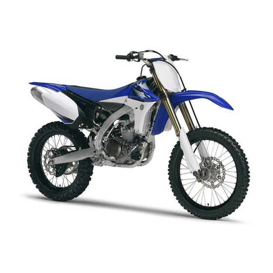
DESCRIPTION DESCRIPTION 1. Clutch lever 10. Coolant drain bolt 2. Front brake lever 11. Rear brake pedal 3. Throttle grip 12. Valve joint 4. Radiator cap 13. Air cleaner 5. Fuel tank cap 14. Drive chain 6. Engine stop switch 15. -
Page 17: Consumer Information
There are two significant reasons for knowing the serial number of your machine: 1. When ordering parts, you can give the num- ber to your Yamaha dealer for positive iden- tification of the model you own. 2. If your machine is stolen, the authorities will need the number to search for and identify your machine. -
Page 18: Features
FEATURES FEATURES OUTLINE OF THE FI SYSTEM The main function of a fuel supply system is to provide fuel to the combustion chamber at the opti- mum air-fuel ratio in accordance with the engine operating conditions and the atmospheric tempera- ture.Inthe conventional carburetor system, the air-fuel ratio of the mixture that is supplied to the combustionchamber is created by the volume of the intake air and the fuel that is metered by the jet used in the respective carburetor. -
Page 19: Throttle Body
FEATURES FI SYSTEM The fuel pump delivers fuel to the fuel injector via the fuel filter. The pressure regulator maintains the fuel pressure that is applied to the fuel injector at only 324 kPa (3.24 kgf/cm ² , 47.0 psi). According- ly,when the energizing signal from the ECU energizes the fuel injector, the fuel passage opens, caus- ing the fuel to be injected into the intake manifold only during the time the passage remains open. -
Page 20: Included Parts
INCLUDED PARTS INCLUDED PARTS NIPPLE WRENCH This nipple wrench "1" is used to tighten the DETACHABLE SIDESTAND spoke. This sidestand "1" is used to support only the machine when standing or transporting it. • Never apply additional force to the side- stand. - Page 21 INCLUDED PARTS FUEL HOSE JOINT COVER The fuel hose joint covers "1" are used to pre- vent mud, dust, and other foreign material from entering the fuel pump when the fuel hose is disconnected. COUPLER FOR CONNECTING OPTIONAL PART This coupler "1" is used for connection to an op- tional Power Tuner and so on.
-
Page 22: Important Information
5. Keep away from fire. 2. Use proper tools and cleaning equipment. ALL REPLACEMENT PARTS Refer to "SPECIAL TOOLS" section. 1. We recommend to use Yamaha genuine parts for all replacements. Use oil and/or grease recommended by Yamaha for as- sembly and adjustment. - Page 23 IMPORTANT INFORMATION LOCK WASHERS/PLATES AND COTTER CIRCLIPS PINS 1. All circlips should be inspected carefully be- 1. All lock washers/plates "1" and cotter pins fore reassembly. Always replace piston pin must be replaced when they are removed. clips after one use. Replace distorted cir- Lock tab(s) should be bent along the bolt or clips.
-
Page 24: Handling The Electronic Parts
HANDLING THE ELECTRONIC PARTS HANDLING THE ELECTRONIC PARTS Electronic parts are very sensitive. Handle with care and do not give impact. 3. Check: • All connections Loose connection → Connect properly. If the pin "1" on the terminal is flattened, bend it •... -
Page 25: Checking Of Connection
CHECKING OF CONNECTION 5. Check: REMOVING THE QUICK FASTENER • Continuity (with the pocket tester) Do not push the center pin with too much Pocket tester: force. Otherwise, the center pin could be 90890-03112 damaged. Analog pocket tester: YU-03112-C To remove a quick fastener, push the center pin in with a screwdriver, then pull the fastener out. -
Page 26: Special Tools
SPECIAL TOOLS SPECIAL TOOLS The proper special tools are necessary for complete and accurate tune-up and assembly. Using the correct special tool will help prevent damage caused by the use of improper tools or improvised tech- niques. The shape and part number used for the special tool differ by country, so two types are pro- vided. - Page 27 SPECIAL TOOLS Tool name/Part number How to use Illustration Steering nut wrench This tool is used when tighten YU-33975, 90890-01403 the steering ring nut to speci- fication. Cap bolt wrench This tool is used to loosen or YM-01500, 90890-01500 tighten the base valve. Cap bolt ring wrench This tool is used to loosen or YM-01501, 90890-01501...
- Page 28 SPECIAL TOOLS Tool name/Part number How to use Illustration Pressure gauge. This tool is used to measure YU-03153, 90890-03153 the fuel pressure. FI diagnostic tool This tool is used to check the YU-03182, 90890-03182 fault codes and diagnose any problems. Fuel pressure adapter This tool is used to attach the YM-03186, 90890-03186...
- Page 29 SPECIAL TOOLS Tool name/Part number How to use Illustration Clutch holding tool This tool is used to hold the YM-91042, 90890-04086 clutch when removing or in- stalling the clutch boss secur- ing nut. Valve guide remover This tool is needed to remove 5.5 mm (0.22 in) and install the valve guide.
- Page 30 Ignition checker tem components. 90890-06754 Digital tachometer This tool is needed for ob- YU-39951-B, 90890-06760 serving engine rpm. YAMAHA Bond No. 1215 This sealant (Bond) is used ® (ThreeBond No. 1215) for crankcase mating surface, 90890-85505 etc.
-
Page 31: Control Functions
CONTROL FUNCTIONS CONTROL FUNCTIONS KICKSTARTER CRANK Rotate the kickstarter crank "1" away from the ENGINE STOP SWITCH engine. Push the starter down lightly with your The engine stop switch "1" is located on the left foot until the gears engage, then kick smoothly handlebar. - Page 32 CONTROL FUNCTIONS REAR BRAKE PEDAL The rear brake pedal "1" is located on the right side of the machine. Press down on the brake pedal to activate the rear brake. STARTER KNOB/IDLE SCREW The starter knob/idle screw "1" is used when starting a cold engine.
-
Page 33: Starting And Break-In
(Excess oil in the element may adversely affect engine starting.) Your Yamaha engine has been designed to use premium unleaded gasoline with a pump oc- STARTING A COLD ENGINE tane number [(R+M)/2] of 91 or higher, or a re- 1. - Page 34 STARTING AND BREAK-IN 6. When the engine starts running, warm it up BREAK-IN PROCEDURES one or two minutes at a steady speed (of 1. Before starting the engine, fill the fuel tank 3,000 to 5,000 r/min), and then return the with the fuel.
-
Page 35: Torque-Check Points
TORQUE-CHECK POINTS TORQUE-CHECK POINTS Frame construction Frame to rear frame Combined seat and fuel tank Fuel tank to frame Exhaust system Silencer to rear frame Engine mounting Frame to engine Engine bracket to engine Engine bracket to frame Steering Steering stem to handlebar Steering stem to frame Steering stem to upper bracket Upper bracket to handlebar... -
Page 36: Cleaning And Storage
CLEANING AND STORAGE CLEANING AND STORAGE STORAGE If your machine is to be stored for 60 days or CLEANING more, some preventive measures must be tak- Frequent cleaning of your machine will en- en to avoid deterioration. After cleaning the ma- hance its appearance, maintain good overall chine thoroughly, prepare it for storage as performance, and extend the life of many com-... -
Page 37: General Specifications
GENERAL SPECIFICATIONS SPECIFICATIONS GENERAL SPECIFICATIONS Model name: YZ450FA (USA, CDN, AUS) YZ450F (EUROPE, NZ, ZA) Model code number: 33D5 (USA,CDN) 33D6 (EUROPE) 33D8 (AUS, NZ, ZA) Dimensions: USA, CDN EUROPE AUS, NZ, ZA Overall length 2,193 mm 2,191 mm 2,194 mm (86.34 in) (86.26 in) (86.38 in) - Page 38 GENERAL SPECIFICATIONS Oil capacity: Engine oil Periodic oil change 0.95 L (0.84 Imp qt, 1.00 US qt) With oil filter replacement 1.0 L (0.88 Imp qt, 1.06 US qt) Total amount 1.2 L (1.06 Imp qt, 1.27 US qt) Coolant capacity (including all routes): 1.13 L (0.99 Imp qt, 1.19 US qt) Air filter: Wet type element...
-
Page 39: Chassis
GENERAL SPECIFICATIONS Chassis: USA, CDN EUROPE AUS, NZ, ZA Frame type Semi double ← ← cradle Caster angle 26.9° 26.8° 26.9° Trail 118.6 mm 117.5 mm 119.0 mm (4.67 in) (4.63 in) (4.69 in) Tire: Type With tube Size (front) 80/100-21 51M Size (rear) 120/80-19 63M (For USA, CDN, AUS, NZ, ZA) -
Page 40: Maintenance Specifications
MAINTENANCE SPECIFICATIONS MAINTENANCE SPECIFICATIONS ENGINE Item Standard Limit Cylinder head: Warp limit ---- 0.05 mm (0.002 in) Cylinder: Bore size 97.00–97.01 mm (3.8189–3.8193 ---- Out of round limit ---- 0.05 mm (0.002 in) Camshaft: Drive method Chain drive (Left) ---- Camshaft cap inside diameter 22.000–22.021 mm ----... - Page 41 MAINTENANCE SPECIFICATIONS Item Standard Limit Camshaft runout limit ---- 0.03 mm (0.0012 in) Timing chain: Timing chain type/No. of links 98XRH2010-122M/122 ---- Timing chain adjustment method Automatic ---- Valve, valve seat, valve guide: Valve clearance (cold) 0.10–0.15 mm (0.0039–0.0059 in) ---- 0.20–0.25 mm (0.0079–0.0098 in) ---- Valve dimensions: "A"...
- Page 42 MAINTENANCE SPECIFICATIONS Item Standard Limit "D" margin thickness (IN) 1.3 mm (0.0512 in) ---- "D" margin thickness (EX) 1.0 mm (0.0394 in) ---- Stem outside diameter (IN) 5.475–5.490 mm (0.2156–0.2161 5.445 mm (0.2144 in) Stem outside diameter (EX) 5.465–5.480 mm (0.2152–0.2157 5.435 mm (0.2140 in) Guide inside diameter (IN)
-
Page 43: Specifications
MAINTENANCE SPECIFICATIONS Item Standard Limit Tilt limit* (IN) ---- 2.5°/1.8 mm (2.5°/0.071 Tilt limit* (EX) ---- 2.5°/1.6 mm (2.5°/0.063 Direction of winding (top view) (IN) Clockwise ---- Direction of winding (top view) (EX) Clockwise ---- Piston: Piston to cylinder clearance 0.020–0.045 mm (0.0008–0.0018 0.1 mm (0.004 in) - Page 44 MAINTENANCE SPECIFICATIONS Item Standard Limit 2nd ring: Type Taper ---- Dimensions (B × T) 1.00 × 3.10 mm (0.04 × 0.12 in) ---- End gap (installed) 0.35–0.50 mm (0.014–0.020 in) 0.85 mm (0.033 in) Side clearance 0.020–0.060 mm (0.0008–0.0024 0.120 mm (0.0047 in) Oil ring: Dimensions (B ×...
-
Page 45: Engine
MAINTENANCE SPECIFICATIONS Item Standard Limit Clutch spring free length 50.0 mm (1.97 in) 49.0 mm (1.93 in) Quantity ---- Clutch housing thrust clearance 0.10–0.35 mm (0.0039–0.0138 in) ---- Clutch housing radial clearance 0.010–0.044 mm (0.0004–0.0017 ---- Clutch release method Inner push, cam push ---- Shifter: Shifter type... -
Page 46: Chassis
MAINTENANCE SPECIFICATIONS Item Standard Limit Lubrication system: Oil filter type Paper type ---- Oil pump type Trochoid type ---- Tip clearance 0.12 mm or less (0.0047 in or less) 0.20 mm (0.008 in) Side clearance 0.09–0.17 mm (0.0035–0.0067 in) 0.24 mm (0.009 in) Housing and rotor clearance 0.03–0.10 mm (0.0012–0.0039 in) 0.17 mm... - Page 47 MAINTENANCE SPECIFICATIONS Item Standard Limit Rear suspension: EUROPE, AUS, USA, CDN NZ, ZA Shock absorber travel 132.0 mm (5.20 in) ← ---- Spring free length 260 mm (10.24 in) 254.8 mm ← (10.03 in) Fitting length 252 mm (9.92 in) 253 mm (9.96 in) ---- Preload length...
-
Page 48: Electrical
Item Standard Limit Ignition system: Advancer type Electrical ---- AC magneto: Magneto-model (stator)/manufacturer 33D00/YAMAHA ---- Stator coil resistance (color) 0.60–0.90 Ωat 20 °C (68 °F) ---- (White–White) Crankshaft position sensor resistance (color) 248–372 Ωat 20 °C (68 °F) ---- (Gray–Black) -
Page 49: Tightening Torques
TIGHTENING TORQUES TIGHTENING TORQUES ENGINE △ - marked portion shall be checked for torque tightening after break-in or before each race. Tightening torque Part to be tightened Thread size Q'ty m•kg ft•lb Spark plug M10S × 1.0 Camshaft cap M6 × 1.0 Cylinder head blind plug screw M12 ×... - Page 50 TIGHTENING TORQUES Tightening torque Part to be tightened Thread size Q'ty m•kg ft•lb Coolant drain bolt M6 × 1.0 Oil pump cover M4 × 0.7 Oil pump M6 × 1.0 Oil pump drive gear shaft M6 × 1.0 Oil filter element cover M6 ×...
- Page 51 TIGHTENING TORQUES *1: Tighten the cylinder head bolts to 30 Nm (3.0 m•kg, 22 ft•lb) in the proper tightening sequence, remove and retighten the cylinder head bolts to 20 Nm (2.0 m•kg, 14 ft•lb) in the proper tightening sequence, and then tighten the cylinder head bolts further to reach the specified angle 150° in the proper tightening sequence.
- Page 52 TIGHTENING TORQUES Tightening torque Part to be tightened Thread size Q'ty m•kg ft•lb △ Front wheel axle holder M8 × 1.25 △ Front brake disc and wheel hub M6 × 1.0 △ Rear brake disc and wheel hub M6 × 1.0 △...
- Page 53 TIGHTENING TORQUES Tightening torque Part to be tightened Thread size Q'ty m•kg ft•lb △ Fuel tank mounting boss and frame M10 × 1.25 △ Fuel tank (front) M6 × 1.0 Fuel tank bracket (front) M6 × 1.0 △ Fuel tank (rear) M6 ×...
- Page 54 TIGHTENING TORQUES ELECTRICAL Tightening torque Part to be tightened Thread size Q'ty m•kg ft•lb Stator M5 × 0.8 Rotor M12 × 1.25 Crankshaft position sensor M6 × 1.0 Throttle position sensor M5 × 0.8 Injector M5 × 0.8 Ignition coil M5 ×...
- Page 55 TIGHTENING TORQUES GENERAL TORQUE SPECIFICATIONS This chart specifies torque for standard fasten- ers with standard I.S.O. pitch threads. Torque specifications for special components or as- semblies are included in the applicable sec- tions of this book. To avoid warpage, tighten multi-fastener assemblies in a crisscross fash- ion, in progressive stages, until full torque is reached.
- Page 56 TIGHTENING TORQUES DEFINITION OF UNITS Unit Read Definition Measure millimeter meter Length centimeter meter Length kilogram gram Weight Newton 1 kg × m/sec Force Newton meter N × m Torque m•kg Meter kilogram m × kg Torque Pascal Pressure N/mm Newton per millimeter N/mm Spring rate...
-
Page 58: Lubrication Diagrams
LUBRICATION DIAGRAMS LUBRICATION DIAGRAMS 2-21... - Page 59 LUBRICATION DIAGRAMS 1. Oil strainer 2. Oil check bolt 3. Scavenging pump 4. Oil feed pump 5. Oil filter element 6. Crankshaft 7. Oil nozzle 8. Exhaust camshaft 9. Intake camshaft 10. Main axle 11. Drive axle 12. Oil level check window 13.
-
Page 60: Cable Routing Diagram
CABLE ROUTING DIAGRAM CABLE ROUTING DIAGRAM 2-23... - Page 61 CABLE ROUTING DIAGRAM 1. Fuel tank breather hose A. Insert the end of the fuel tank breather 2. Coupler for connecting optional part hose into the hole in the steering stem. 3. Cylinder head breather hose B. Fit the accessory coupler into the connec- 4.
- Page 62 CABLE ROUTING DIAGRAM 100mm 2-25...
- Page 63 CABLE ROUTING DIAGRAM 1. Clutch cable A. Pass the clutch cable, throttle cables, and 2. Throttle cable (return) engine stop switch lead through the cable 3. Throttle cable (pull) holder. Pass the clutch cable through the 4. Cable holder lower guide only. 5.
- Page 64 CABLE ROUTING DIAGRAM 2-27...
- Page 65 CABLE ROUTING DIAGRAM Fit the bracket into the hole in the rubber 1. Tension pipe portion of the condenser. 2. Coolant temperature sensor coupler J. Fasten the radiator breather hose to the 3. Front engine bracket frame with the plastic band, making sure to 4.
- Page 66 CABLE ROUTING DIAGRAM 2-29...
- Page 67 CABLE ROUTING DIAGRAM 1. Ignition coil coupler A. Route the fuel pump lead to the outside of 2. Coolant temperature sensor lead the fuel hose and above the cover. 3. Atmospheric pressure sensor coupler B. Route the spark plug wire between the 4.
- Page 68 CABLE ROUTING DIAGRAM 2-31...
- Page 69 CABLE ROUTING DIAGRAM 1. Brake master cylinder A. Install the brake hose so that its pipe por- 2. Brake hose holder tion directs as shown and lightly touches 3. Brake hose the projection on the brake caliper. B. Pass the brake hose into the brake hose holders.
- Page 70 CABLE ROUTING DIAGRAM 2-33...
- Page 71 CABLE ROUTING DIAGRAM A. Route the clutch cable to the rear of the 1. Throttle cable number plate band. 2. Clutch cable B. Fasten the engine stop switch lead to the 3. Clamp handlebar. 4. Engine stop switch lead C. Route the brake hose to the front of the 5.
-
Page 72: Maintenance Intervals
If you are a doubt as to what intervals to follow in maintaining and lubricating your machine, consult your Yamaha dealer. •Periodic inspection is essential in making full use of the machine performance. The service life of the parts varies substantially according to the environment in which the machine runs (e.g., rain,... - Page 73 MAINTENANCE INTERVALS Every Every Every race third fifth After As re- Item (about (about (about Remarks break-in quired 12.5 hours) hours) hours) PISTON Inspect Inspect crack. ● Clean Inspect carbon deposits ● and eliminate them. Replace Replace the piston, pis- ●...
- Page 74 MAINTENANCE INTERVALS Every Every Every race third fifth After As re- Item (about (about (about Remarks break-in quired 12.5 hours) hours) hours) EXHAUST PIPE, SI- LENCER, PROTEC- Inspect and retighten ● ● Clean ● * When the exhaust sound becomes louder Replace fiver ●...
- Page 75 MAINTENANCE INTERVALS Every Every Every race third fifth After As re- Item (about (about (about Remarks break-in quired 12.5 hours) hours) hours) ENGINE GUARD Replace Breakage ● FRAME Clean and inspect ● ● FUEL TANK, FUEL PUMP inspect ● ● FUEL HOSE Inspect ●...
- Page 76 Retighten sprocket ● ● bolt Inspect bearings ● Replace bearings ● Lubricate Lithium base grease ● THROTTLE, CON- TROL CABLE Check routing and Yamaha cable lube or ● ● connection SAE 10W-40 motor oil Lubricate ● ●...
-
Page 77: Pre-Operation Inspection And Maintenance
PRE-OPERATION INSPECTION AND MAINTENANCE PRE-OPERATION INSPECTION AND MAINTENANCE Before riding for break-in operation, practice or a race, make sure the machine is in good operating condition. Before using this machine, check the following points. GENERAL INSPECTION AND MAINTENANCE Item Routine Page Check that coolant is filled up to the radiator cap. -
Page 78: Engine
ENGINE ENGINE CHANGING THE COOLANT CHECKING THE COOLANT LEVEL Do not remove the radiator cap when the en- gine is hot. Do not remove the radiator cap "1", drain bolt and hoses when the engine and radia- tor are hot. Scalding hot fluid and steam Take care so that coolant does not splash may be blown out under pressure, which on painted surfaces. - Page 79 ENGINE CHECKING THE RADIATOR CAP 1. Inspect: • Do not mix more than one type of ethylene • Seal (radiator cap) "1" glycol antifreeze containing corrosion in- • Valve and valve seat "2" hibitors for aluminum engine. Crack/damage → Replace. •...
- Page 80 ENGINE CHECKING THE COOLING SYSTEM 1. Inspect: • Coolant level 2. Attach: • Radiator cap tester "1" and adapter "2" Radiator cap tester: YU-24460-01/90890-01325 Radiator cap tester adapter: YU-33984/90890-01352 c. Tighten the locknuts. Locknut: 5 Nm (0.5 m•kg, 3.6 ft•lb) 2.
- Page 81 ENGINE 2. Adjust: • Throttle grip free play • Before adjustment, expose the adjuster by moving the boot "3" and cap "4" away. • Make minute adjustment on the lever side us- Throttle grip free play adjustment steps: ing the adjuster "5". a.
- Page 82 ENGINE 2. Apply: • Lithium soap base grease On the throttle cable end "a". 3. Remove: • Mounting bolt for air filter case cover 4. Loosen and release the binder "1" and lift 3. Install: the air filter case lid. •...
- Page 83 ENGINE 6. Clean: b. Clean the air filter element 2 with solvent. • Air filter element Clean them with solvent. After cleaning, remove the remaining solvent by squeezing the element. After cleaning, remove the remaining solvent by squeezing the element. Do not twist the element when squeezing the element.
- Page 84 ENGINE 3. Inspect: • Oil level Make sure that the engine oil level is be- tween the maximum level line "a" and mini- mum level line "b" shown for the oil level check window. Above the upper limit "a" → Check that no oil comes out when the check bolt "1"...
- Page 85 ENGINE Recommended brand: YAMALUBE Replacement steps: Recommended engine oil type a. Remove the oil filter element cover "1" and SAE10W-30, SAE 10W-40, oil filter element "2". SAE10W-50, SAE 15W-40, SAE b. Check the O-rings "3", if cracked or dam- 20W-40 or SAE 20W-50 aged, replace them with a new one.
- Page 86 ENGINE 7. Install: 2. Use a temperature probe tester "1" and con- • Oil filler cap tact it to the drain bolt thread. 8. Inspect: Oil temperature: • Engine (for oil leaks) 55.0–65.0 °C (131–149°F) • Oil level CHECKING THE OIL PRESSURE 1.
- Page 87 "b" on the crank- basic knowledge and skill concerning the ser- case cover. vicing of Yamaha motorcycles (e.g., Yamaha dealers, service engineers, etc.) Those who have little knowledge and skill concerning ser- vicing are requested not to undertake inspec- tion, adjustment, disassembly, or reassembly only by reference to this manual.
- Page 88 ENGINE c. Measure the valve clearance "e" using a feeler gauge "1". Record the measured reading if the clearance is incorrect. c. Select the proper pad using the pad select- ing table. Pad Availability: 25 Pad range increments 1.20 Pads are available in 120–No.
- Page 89 ENGINE Use the new pad number only as a guide when verifying the valve clearance adjustment. f. Install the new pads "4" and the valve lifters "5". • Apply the engine oil on the valve lifters. • Apply the molybdenum disulfide oil on the valve stem ends.
- Page 90 ENGINE INTAKE EXHAUST 3-19...
-
Page 91: Chassis
CHASSIS CHASSIS d. Place the other end of the tube into a con- tainer. BLEEDING THE HYDRAULIC BRAKE e. Slowly apply the brake lever or pedal sever- SYSTEM al times. f. Pull the lever in or push down on the pedal. Hold the lever or pedal in position. - Page 92 CHASSIS 2. Remove: 2. Adjust: • Brake lever cover • Brake pedal height 3. Adjust: • Brake lever position Pedal height adjustment steps: a. Loosen the locknut "1". Brake lever position adjustment steps: b. Turn the adjusting nut "2" until the pedal a.
- Page 93 CHASSIS CHECKING AND REPLACING THE FRONT d. Remove the pad pin and brake pads "4". BRAKE PADS 1. Inspect: • Brake pad thickness "a" Out of specification → Replace as a set. Brake pad thickness: 4.4 mm (0.17 in) <Limit>: 1.0 mm (0.04 in) e.
- Page 94 CHASSIS i. Install the brake caliper "8" and tighten the pad pin "9". Bolt (brake caliper): 28 Nm (2.8 m•kg, 20 ft•lb) Pad pin: 18 Nm (1.8 m•kg, 13 ft•lb) 2. Replace: • Brake pad Brake pad replacement steps: a. Remove the protector "1" and pad pin plug "2".
- Page 95 CHASSIS e. Connect the transparent hose "8" to the bleed screw "9" and place the suitable con- tainer under its end. k. Install the pad pin plug "15" and protector "16". Pad pin plug: f. Loosen the bleed screw and push the brake 2 Nm (0.2 m•kg, 1.4 ft•lb) caliper piston in.
- Page 96 CHASSIS 2. Inspect: CHECKING THE SPROCKET • Rear brake pad insulator "1" 1. Inspect: Damage → Replace. • Sprocket teeth "a" Excessive wear → Replace. Replace the drive sprocket, rear wheel sprock- et and drive chain as a set. CHECKING THE BRAKE FLUID LEVEL 1.
- Page 97 CHASSIS 2. Remove: • Master link clip Be sure to install the master link clip to the • Joint "1" direction as shown. • Drive chain "2" 3. Clean: a. Turning direction • Drive chain 6. Lubricate: Place it in kerosene, and brush off as much •...
- Page 98 CHASSIS A. Right B. Left Turn the adjuster so that the drive chain is in line with the sprocket, as viewed from the rear. d. Tighten the axle nut while pushing down the drive chain. Axle nut: 135 Nm (13.5 m•kg, 98 ft•lb) 3.
- Page 99 CHASSIS CLEANING THE FRONT FORK OIL SEAL AND DUST SEAL 1. Remove: • Protector • Dust seal "1" Use a thin screw driver, and be careful not to damage the inner fork tube and dust seal. ADJUSTING THE FRONT FORK REBOUND DAMPING FORCE 1.
- Page 100 CHASSIS ADJUSTING THE FRONT FORK CHECKING THE REAR SHOCK ABSORBER COMPRESSION DAMPING FORCE 1. Inspect: 1. Adjust: • Swingarm smooth action • Compression damping force Abnormal noise/unsmooth action → Grease By turning the adjuster "1". the pivoting points or repair the pivoting points.
- Page 101 CHASSIS e. Tighten the locknut. • The I.D. mark "a" is marked at the end of the Locknut: spring. 30 Nm (3.0 m•kg, 22 ft•lb) • Spring specification varies according to the difference in the production lot. ADJUSTING THE REAR SHOCK 3.
- Page 102 CHASSIS Do not force the adjuster past the minimum or maximum extent of adjustment. The ad- juster may be damaged. ADJUSTING THE REAR SHOCK ABSORBER LOW COMPRESSION DAMPING FORCE 1. Adjust: • Low compression damping force By turning the adjuster "1". ADJUSTING THE REAR SHOCK ABSORBER HIGH COMPRESSION Stiffer "a"...
- Page 103 CHASSIS • STANDARD POSITION: This is the position which is back by the spe- cific number of turns from the fully turned-in position. (Which align the punch mark "a" on the adjuster with the punch mark "b" on the adjuster body.) Standard position: About 1-1/4 turns out * About 1-1/2 turns out...
- Page 104 CHASSIS 3. Check: Spokes: • Steering smooth action 3 Nm (0.3 m•kg, 2.2 ft•lb) Turn the handlebar lock to lock. CHECKING THE WHEELS Unsmooth action → Adjust steering ring nut. 1. Inspect: • Wheel runout Elevate the wheel and turn it. Abnormal runout →...
- Page 105 CHASSIS Steering stem nut: 145 Nm (14.5 m•kg, 105 ft•lb) Handlebar upper holder: 28 Nm (2.8 m•kg, 20 ft•lb) Pinch bolt (upper bracket): 21 Nm (2.1 m•kg, 15 ft•lb) Number plate: 7 Nm (0.7 m•kg, 5.1 ft•lb) e. Loosen the steering ring nut one turn. f.
- Page 106 CHASSIS LUBRICATION 3-35...
- Page 107 6. Drive chain 7. Tube guide cable winding portion 8. Throttle cable end 9. Clutch cable end A. Use Yamaha cable lube or equivalent on these areas. B. Use SAE 10W-40 motor oil or suitable chain lubricants. C. Lubricate the following areas with high quality, lightweight lithium-soap base grease.
-
Page 108: Electrical
ELECTRICAL ELECTRICAL CHECKING THE SPARK PLUG 1. Remove: • Spark plug 2. Inspect: • Electrode "1" Wear/damage → Replace. • Insulator color "2" Normal condition is a medium to light tan color. CHECKING THE IGNITION TIMING Distinctly different color → Check the engine 1. - Page 109 ELECTRICAL 4. Check: • Ignition timing Visually check the stationary pointer "a" is within the firing range "b" on the rotor. Incorrect firing range → Check rotor and Crankshaft position sensor. 5. Install: • Timing mark accessing screw Timing mark accessing screw: 6 Nm (0.6 m•kg, 4.3 ft•lb) 3-38...
-
Page 110: Troubleshooting
If a problem occurs that is not listed in this manual or if the problem cannot be corrected by the procedures provided in this manual, contact your Yamaha dealer. Engine starting problems, engine idling speed problems, and medium and high-speed perfor- mance problems •... - Page 111 "CHECKING THE ECU" section in the Repair. → CHAPTER 7.) OK ↓ Check the assembled condition of the No good throttle body, and check the throttle Repair or clean. → valve and its surrounding parts for dirt. OK ↓ Consult a Yamaha dealer. 3-40...
-
Page 112: Seat And Side Covers
This section is intended for those who have basic knowledge and skill concerning the servicing of Yamaha motorcycles (e.g., Yamaha dealers, service engineers, etc.) Those who have little knowl- edge and skill concerning servicing are requested not to undertake inspection, adjustment, disas- sembly, or reassembly only by reference to this manual. - Page 113 SEAT AND SIDE COVERS REMOVING THE NUMBER PLATE • Affix the insulators in the following order with 1. Remove: the portion "a" overlapping one on another. • Bolt (number plate) • Insulator 1 "1" • Number plate "1" • Insulator 2 "2" •...
-
Page 114: Exhaust Pipe And Silencer
EXHAUST PIPE AND SILENCER EXHAUST PIPE AND SILENCER REMOVING THE EXHAUST PIPE AND SILENCER Order Part name Q'ty Remarks Seat Refer to "SEAT AND SIDE COV- ERS" section. Refer to "SEAT AND SIDE COV- Side cover (left and right) ERS" section. Refer to "SEAT AND SIDE COV- Rear fender ERS"... - Page 115 EXHAUST PIPE AND SILENCER Order Part name Q'ty Remarks Exhaust pipe 1 Gasket Heat protector...
- Page 116 EXHAUST PIPE AND SILENCER CHECKING THE SILENCER AND EXHAUST 3. Replace: PIPE • Fiber "1" 1. Inspect: • Gasket "1" Damage → Replace. 4. Install: • Inner pipe "1" • Bolt "2" CHANGING THE SILENCER FIBER Bolt (silencer): For USA and CDN 8 Nm (0.8 m•kg, 5.8 ft•lb) 2.
- Page 117 EXHAUST PIPE AND SILENCER Except for USA and CDN 1. Remove: • Apply heat-resistant sealant to the areas "a" • Rivet (front) "1" shown, making sure that there are no gaps in • Inner pipe "2" the beads of sealant. •...
- Page 118 EXHAUST PIPE AND SILENCER 2. Install: • Silencer clamp (front) • Eexhaust pipe 2 "1" • Bolt (exhaust pipe 2) "2" 4. Install: •Bolt (exhaust pipe 2): Bolt (exhaust pipe 2): 20 Nm (2.0 m•kg, 14 ft•lb) •Silencer clamp (front): Install and temporarily tighten the exhaust pipe Silencer clamp (front): 2 with its end positioned as shown with respect...
-
Page 119: Radiator
RADIATOR RADIATOR REMOVING THE RADIATOR Order Part name Q'ty Remarks Refer to "CHANGING THE COOL- Drain the coolant. ANT" section in the CHAPTER 3. Refer to "SEAT AND SIDE COV- Seat ERS" section. Fuel tank Refer to "FUEL TANK" section in the CHAPTER 6. - Page 120 RADIATOR Order Part name Q'ty Remarks Radiator breather hose Left radiator Radiator hose 1 Pipe 1/O-ring...
- Page 121 RADIATOR HANDLING NOTE • Radiator hose 4 "7" Radiator hose 4: 2 Nm (0.2 m•kg, 1.4 ft•lb) Do not remove the radiator cap when the en- gine and radiator are hot. Scalding hot fluid and steam may be blown out under pres- sure, which could cause serious injury.
- Page 122 RADIATOR 4. Install: • Radiator breather hose "1" • Right radiator "2" Right radiator: 10 Nm (1.0 m•kg, 7.2 ft•lb) Refer to "CABLE ROUTING DIAGRAM" section in the CHAPTER 2. 5. Install: • Radiator guard "1" First fit the inner hook portion "a" and then the outer one "b"...
-
Page 123: Camshafts
CAMSHAFTS CAMSHAFTS REMOVING THE CYLINDER HEAD COVER Order Part name Q'ty Remarks Refer to "SEAT AND SIDE COV- Seat ERS" section. Refer to "FUEL TANK" section in the Fuel tank CHAPTER 6. Refer to "THROTTLE BODY" section Cover in the CHAPTER 6. Engine upper bracket (left) Spark plug Cylinder head breather hose... - Page 124 CAMSHAFTS REMOVING THE CAMSHAFTS Order Part name Q'ty Remarks Timing mark accessing screw Refer to removal section. Crankshaft end accessing screw Refer to removal section. Timing chain tensioner cap bolt Refer to removal section. Timing chain tensioner Refer to removal section. Gasket Refer to removal section.
- Page 125 CAMSHAFTS REMOVING THE CAMSHAFT 3. Remove: 1. Remove: • Timing chain tensioner cap bolt "1" • Timing mark accessing screw "1" • Timing chain tensioner "2" • Crankshaft end accessing screw "2" • Gasket 2. Align: 4. Remove: • Alignmen mark •...
- Page 126 CAMSHAFTS CHECKING THE CAMSHAFT 3. Measure: 1. Inspect: • Runout (camshaft) • Cam lobe Out of specification → Replace. Pitting/scratches/blue discoloration → Re- Runout (camshaft): place. Less than 0.03 mm (0.0012 in) 2. Measure: • Cam lobe length "a" and "b" Out of specification →...
- Page 127 CAMSHAFTS c. Install the clip, dowel pins and camshaft CHECKING THE CAMSHAFT SPROCKET caps. 1. Inspect: • Camshaft sprocket "1" Bolt (camshaft cap): Wear/damage → Replace the camshaft as- 10 Nm (1.0 m•kg, 7.2 ft•lb) sembly and timing chain as a set. •...
- Page 128 CAMSHAFTS The alignment mark "a" on the rotor is there for camshaft installation. This alignment mark is stamped 23° ATDC. c. Fit the timing chain "3" onto both camshaft sprockets and install the camshafts on the cylinder head. Make sure that the alignment mark "c" on the INSTALLING THE CAMSHAFT exhaust camshaft sprocket and the alignment 1.
- Page 129 CAMSHAFTS d. Install the clips, camshaft caps "4" and bolts b. With the rod fully wound and the chain ten- (camshaft cap) "5". sioner UP mark "a" facing upward, install the gasket "1", the timing chain tensioner "2", Bolt (camshaft cap): and the gasket "3", and tighten the bolt "4"...
-
Page 130: Cylinder Head
CYLINDER HEAD CYLINDER HEAD REMOVING THE CYLINDER HEAD Order Part name Q'ty Remarks Refer to "SEAT AND SIDE COV- Seat ERS" section. Fuel tank Refer to "FUEL TANK" section in the CHAPTER 6. Refer to "EXHAUST PIPE AND SI- Exhaust pipe and silencer LENCER"... - Page 131 CYLINDER HEAD Order Part name Q'ty Remarks Coolant temperature sensor Oil check bolt Oil passage plug Tighten the cylinder head bolts to 30 Nm (3.0 m•kg, 22 ft•b) in the proper tightening sequence, re- move and retighten the cylinder head bolts to 20 Nm (2.0 m•kg, 14 ft•lb) in the proper tightening se- quence, and then tighten the cylinder head bolts further to reach the specified angle 150°...
- Page 132 CYLINDER HEAD CHECKING THE CYLINDER HEAD 1. Eliminate: • Carbon deposits (from the combustion chambers) Use a rounded scraper. Do not use a sharp instrument to avoid damag- ing or scratching: • Spark plug threads • Valve seats INSTALLING THE CYLINDER HEAD 1.
- Page 133 CYLINDER HEAD a. Wash the threads and contact surfaces of h. Put a mark on the corner "1" of the bolt (cyl- the bolts, the contact surfaces of the plain inder head) and the cylinder head "2" as washers, the contact surface of the cylinder shown.
-
Page 134: Valves And Valve Springs
VALVES AND VALVE SPRINGS VALVES AND VALVE SPRINGS REMOVING THE VALVES AND VALVE SPRINGS Order Part name Q'ty Remarks Cylinder head Refer to "CYLINDER HEAD" section. Valve lifter Refer to removal section. Adjusting pad Refer to removal section. Valve cotter Refer to removal section. - Page 135 VALVES AND VALVE SPRINGS REMOVING THE VALVE LIFTER AND 3. Remove: VALVE COTTER • Valve cotter 1. Remove: • Valve lifter "1" Remove the valve cotters by compressing the • Pad "2" valve spring with the valve spring compressor "1" and the valve spring compressor attach- Identify each lifter "1"...
- Page 136 VALVES AND VALVE SPRINGS 2. Replace: Valve guide remover & installer set • Valve guide (ø5.5): 90890-04016 Replacement steps: Valve guide remover (5.5 mm): YM-01122 Valve guide installer (5.5 mm): To ease guide removal, installation and to YM-04015 maintain correct fit heat the cylinder head in an Valve guide reamer (5.5 mm): over to 100 °C (212 °F).
- Page 137 VALVES AND VALVE SPRINGS 5. Measure: • Runout (valve stem) Measurement steps: Out of specification → Replace. a. Apply Mechanic's blueing dye (Dykem) "b" to the valve face. Runout limit: 0.01 mm (0.0004 in) • When installing a new valve always replace the guide.
- Page 138 VALVES AND VALVE SPRINGS h. Press the valve through the valve guide and onto the valve seat to make a clear pattern. i. Measure the valve seat width again. If the valve seat width is out of specification, reface and relap the valve seat. CHECKING THE VALVE SPRINGS 1.
- Page 139 VALVES AND VALVE SPRINGS 3. Measure: • Spring tilt "a" Out of specification → Replace. Spring tilt limit: Intake: 2.5°/1.8 mm (0.070 in) Exhaust: 2.5°/1.6 mm (0.062 in) CHECKING THE VALVE LIFTERS 1. Inspect: e. Smaller pitch • Valve lifter 3.
- Page 140 VALVES AND VALVE SPRINGS 4. To secure the valve cotters onto the valve stem, lightly tap the valve tip with a piece of wood. Hitting the valve tip with excessive force could damage the valve. 5. Install: • Adjusting pad "1" •...
-
Page 141: Cylinder And Piston
CYLINDER AND PISTON CYLINDER AND PISTON REMOVING THE CYLINDER AND PISTON Order Part name Q'ty Remarks Cylinder head Refer to "CYLINDER HEAD" section. Bolt (cylinder) Cylinder Gasket Dowel pin Piston pin clip Refer to removal section. Piston pin Refer to removal section. Piston Refer to removal section. - Page 142 CYLINDER AND PISTON REMOVING THE PISTON AND PISTON RING 1. Remove: • Piston pin clip "1" • Piston pin "2" • Piston "3" • Put identification marks on each piston head for reference during reinstallation. • Before removing each piston pin, deburr the clip groove and pin hole area.
- Page 143 CYLINDER AND PISTON b. If out of specification, replace the cylinder, and replace the piston and piston rings as set. c. Measure the piston skirt diameter "P" with a micrometer. 2. Position: • Piston ring (in cylinder) Insert a ring into the cylinder and push it ap- a.
- Page 144 CYLINDER AND PISTON CHECKING THE PISTON PIN d. If out of specification, replace the piston. 1. Inspect: Piston pin-to-piston clearance: • Piston pin 0.004–0.024 mm (0.00016–0.00094 Blue discoloration/grooves → Replace, then inspect the lubrication system. <Limit>:0.07 mm (0.003 in) 2. Measure: •...
- Page 145 CYLINDER AND PISTON 3. Install: • Piston "1" • Piston pin "2" • Piston pin clip "3" • Apply engine oil onto the piston. • Apply molybdenum disulfide oil onto the pis- ton pin. • Install the piston with the F mark "a" on it pointing to its intake (front) side.
-
Page 146: Clutch
CLUTCH CLUTCH REMOVING THE CLUTCH Order Part name Q'ty Remarks Refer to "CHANGING THE ENGINE Drain the engine oil. OIL" section in the CHAPTER 3. Refer to "ENGINE REMOVAL" sec- Brake pedal tion. Clutch cable Disconnect at engine side. Clutch cover Gasket Clutch spring Pressure plate... - Page 147 CLUTCH Order Part name Q'ty Remarks Clutch plate Friction plate Nut (clutch boss) Refer to removal section. Conical washer Refer to removal section. Clutch boss Refer to removal section. Thrust washer Primary driven gear Push lever shaft 4-36...
- Page 148 CLUTCH REMOVING THE CLUTCH BOSS CHECKING THE PRIMARY DRIVEN GEAR 1. Remove: 1. Check: • Nut "1" • Circumferential play • Conical washer "2" Free play exists → Replace. • Clutch boss "3" • Gear teeth "a" Wear/damage → Replace. Use the clutch holding tool "4"...
- Page 149 CLUTCH CHECKING THE PUSH ROD 1. Inspect: • Push rod 1 "1" • Bearing "2" • Washer "3" • Push rod 2 "4" • Ball "5" Wear/damage/bend → Replace. CHECKING THE CLUTCH PLATES 1. Measure: • Clutch plate warpage Out of specification → Replace clutch plate as a set.
- Page 150 CLUTCH 2. Install: A. For USA and CDN • Conical washer "1" B. Except for USA and CDN • Nut (clutch boss) "2" 3. Install: • Friction plate "1" Nut (clutch boss): • Clutch plate "2" 75 Nm (7.5 m•kg, 54 ft•lb) •...
- Page 151 CLUTCH 5. Install: 8. Install: • Push rod 2 "1" • O-ring (clutch cover) "1" • Ball "2" • Push rod 1 "3" Apply the lithium soap base grease on the O- ring Apply the engine oil on the push rod 1, 2 and ball.
-
Page 152: Oil Filter Element And Water Pump
OIL FILTER ELEMENT AND WATER PUMP OIL FILTER ELEMENT AND WATER PUMP REMOVING THE OIL FILTER ELEMENT AND WATER PUMP Order Part name Q'ty Remarks Refer to "ENGINE REMOVAL" sec- Right engine guard tion. Refer to "CHANGING THE ENGINE Drain the engine oil. OIL"... - Page 153 OIL FILTER ELEMENT AND WATER PUMP Order Part name Q'ty Remarks Dowel pin Kickstarter crank Right crankcase cover Gasket Dowel pin/O-ring Impeller Refer to removal section. Washer Refer to removal section. Impeller shaft Refer to removal section. Oil seal 1 Refer to removal section.
- Page 154 OIL FILTER ELEMENT AND WATER PUMP REMOVING THE IMPELLER SHAFT 1. Remove: 1. Remove: • Bearing "1" • Impeller "1" • Oil seal "2" • Washer "2" • Impeller shaft "3" Hold the impeller shaft on its width across the flats "a"...
- Page 155 OIL FILTER ELEMENT AND WATER PUMP CHECKING THE BEARING 2. Install: 1. Inspect: • Bearing "1" • Bearing Rotate inner race with a finger. Install the bearing by pressing its outer race Rough spot/seizure → Replace. parallel. CHECKING THE OIL SEAL INSTALLING THE IMPELLER SHAFT 1.
- Page 156 OIL FILTER ELEMENT AND WATER PUMP INSTALLING THE RIGHT CRANKCASE COVER 1. Install: • Dowel pin "1" • O-ring "2" • Collar "3" • Gasket "4" Apply the lithium soap base grease on the O- ring. INSTALLING THE KICKSTARTER CRANK 1.
- Page 157 OIL FILTER ELEMENT AND WATER PUMP INSTALLING THE WATER PUMP HOUSING 1. Install: • Dowel pin "1" • Gasket "2" INSTALLING THE OIL FILTER ELEMENT 1. Install: • Oil filter element "1" • O-ring "2" 2. Install: • Oil filter element cover "3" •...
-
Page 158: Balancer
BALANCER BALANCER REMOVING THE BALANCER Order Part name Q'ty Remarks Primary driven gear Refer to "CLUTCH" section. Refer to "OIL FILTER ELEMENT Right crankcase cover AND WATER PUMP" section. Stator Refer to "AC MAGNETO" section. Nut (balancer) Refer to removal section. Nut (primary drive gear) Refer to removal section. - Page 159 BALANCER Order Part name Q'ty Remarks Balancer shaft driven gear 4-48...
- Page 160 BALANCER REMOVING THE BALANCER CHECKING THE PRIMARY DRIVE GEAR, 1. Straighten the lock washer tab. BALANCER SHAFT DRIVE GEAR AND 2. Loosen: BALANCER SHAFT DRIVEN GEAR • Nut (balancer) "1" 1. Inspect: • Nut (primary drive gear) "2" • Primary drive gear "1" •...
- Page 161 BALANCER 2. Install: • Balancer shaft driven gear "1" • Align the punched mark "a" on the balancer shaft drive gear with the punched mark "b" on the balancer shaft driven gear. • Install the balancer shaft driven gear and crankshaft with the lower splines "c"...
-
Page 162: Oil Pump
OIL PUMP OIL PUMP REMOVING THE OIL PUMP Order Part name Q'ty Remarks Primary driven gear Refer to "CLUTCH" section. Refer to "OIL FILTER ELEMENT Right crankcase cover AND WATER PUMP" section. Circlip Washer Oil pump drive gear Oil pump assembly Dowel pin Outer rotor 2 Circlip... - Page 163 OIL PUMP Order Part name Q'ty Remarks Inner rotor 1 Dowel pin Washer Oil pump drive shaft Rotor housing 4-52...
- Page 164 OIL PUMP CHECKING THE OIL PUMP 3. Check: 1. Inspect: • Unsmooth → Repeat steps #1 and #2 or re- • Oil pump drive gear place the defective parts. • Oil pump drive shaft • Rotor housing • Oil pump cover Cracks/wear/damage →...
- Page 165 OIL PUMP 3. Install: 5. Install: • Oil pump cover "1" • Oil pump drive gear "1" • Screw (oil pump cover) "2" • Washer "2" • Circlip"3" Screw (oil pump cover): 2 Nm (0.2 m•kg, 1.4 ft•lb) Apply the engine oil on the oil pump drive gear •...
-
Page 166: Kick Shaft And Shift Shaft
KICK SHAFT AND SHIFT SHAFT KICK SHAFT AND SHIFT SHAFT REMOVING THE KICK SHAFT AND SHIFT SHAFT Order Part name Q'ty Remarks Oil pump Refer to "OIL PUMP" section. Kick idle gear Kick shaft assembly Refer to removal section. Spring guide Torsion spring Ratchet wheel Kick gear... - Page 167 KICK SHAFT AND SHIFT SHAFT Order Part name Q'ty Remarks Shift guide Refer to removal section. Shift lever assembly Refer to removal section. Shift lever Pawl Pawl pin Spring Bolt (stopper lever) Stopper lever Torsion spring Segment Refer to removal section. 4-56...
- Page 168 KICK SHAFT AND SHIFT SHAFT REMOVING THE KICK SHAFT ASSEMBLY 1. Remove: • Kick shaft assembly "1" Unhook the torsion spring "2" from the hole "a" in the crankcase. CHECKING THE KICK SHAFT AND RATCHET WHEEL 1. Check: • Ratchet wheel "1" smooth movement Unsmooth movement →...
- Page 169 KICK SHAFT AND SHIFT SHAFT CHECKING THE SHIFT SHAFT INSTALLING THE SEGMENT 1. Inspect: 1. Install: • Shift shaft "1" • Segment "1" Bend/damage → Replace. • Bolt (segment) • Spring "2" Bolt (segment): Broken → Replace. 30 Nm (3.0 m•kg, 22 ft•lb) Align the notch "a"...
- Page 170 KICK SHAFT AND SHIFT SHAFT INSTALLING THE SHIFT GUIDE AND SHIFT 4. Install: LEVER ASSEMBLY • Bolt (shift guide) "1" 1. Install: Bolt (shift guide): • Spring "1" 10 Nm (1.0 m•kg, 7.2 ft•lb) • Pawl pin "2" • Pawl "3" To shift lever "4".
- Page 171 KICK SHAFT AND SHIFT SHAFT INSTALLING THE KICK SHAFT ASSEMBLY 3. Install: 1. Install: • Spring guide "1" • Kick gear "1" • Washer "2" Slide the spring guide into the kick shaft, make • Circlip "3" sure the groove "a" in the spring guide fits on •...
- Page 172 KICK SHAFT AND SHIFT SHAFT 5. Hook: • Torsion spring "1" Turn the torsion spring clockwise and hook into the proper hole "a" in the crankcase. INSTALLING THE KICK IDLE GEAR 1. Install: • Kick idle gear "1" • Washer "2" •...
-
Page 173: Ac Magneto
AC MAGNETO AC MAGNETO REMOVING THE AC MAGNETO Order Part name Q'ty Remarks Seat Refer to "SEAT AND SIDE COV- ERS" section. Fuel tank Refer to "FUEL TANK" section in the CHAPER 6. Disconnect the AC magneto lead Left crankcase cover Gasket Dowel pin Nut (rotor) - Page 174 • Rotor inner surface "a" •Install the holder so that the projection "c" on • Stator outer surface "b" the holder contacts the stopper. Damage→Inspect the crankshaft runout and crankshaft bearing. YAMAHA Bond No. 1215 (Three- ® Bond No. 1215): 90890-85505 4-63...
- Page 175 AC MAGNETO 2. Install: 5. Install: • Woodruff key "1" • Dowel pin • Rotor "2" • Gasket (left crankcase cover) • Left crankcase cover "1" • Hose guide (cylinder head breather hose) • Degrease the contact surfaces of the tapered "2"...
-
Page 176: Engine Removal
ENGINE REMOVAL ENGINE REMOVAL REMOVING THE ELECTRONIC PARTS Order Part name Q'ty Remarks Hold the machine by placing the suit- Refer to "HANDLING NOTE". able stand under the frame. Refer to "SEAT AND SIDE COV- Seat ERS" section. Fuel tank Air filter case Radiator Refer to "RADIATOR"... - Page 177 ENGINE REMOVAL REMOVING THE ENGINE Order Part name Q'ty Remarks Hold the machine by placing the suit- Refer to "HANDLING NOTE". able stand under the frame. Refer to "THROTTLE BODY" section Throttle body in the CHAPRE 6. Refer to "SEAT AND SIDE COV- Rear fender ERS"...
- Page 178 ENGINE REMOVAL Order Part name Q'ty Remarks Lock washer Refer to removal section. Drive sprocket Refer to removal section. Clip Bolt (brake pedal) Brake pedal Upper engine bracket Lower engine bracket Engine mounting bolt Pivot shaft Refer to removal section. Engine Refer to removal section.
- Page 179 ENGINE REMOVAL HANDLING NOTE Support the machine securely so there is no danger of it falling over. REMOVING THE DRIVE SPROCKET 1. Remove: • Nut (drive sprocket) "1" • Lock washer "2" 2. Remove: • Straighten the lock washer tab. •...
- Page 180 ENGINE REMOVAL • Upper engine bracket "8" • Bolt (upper engine bracket) "9" Bolt (upper engine bracket): 45 Nm (4.5 m•kg, 32 ft•lb) • Engine mounting bolt (upper) "10" Engine mounting bolt (upper): 45 Nm (4.5 m•kg, 32 ft•lb) • Apply the molybdenum disulfide grease on INSTALLING THE DRIVE SPROCKET the pivot shaft.
- Page 181 ENGINE REMOVAL 3. Bend the lock washer tab to lock the nut. 4. Install: • Drive chain sprocket guide • Drive chain sprocket cover "1" • Bolt(drive chain sprocket cover) "2" Bolt (drive chain sprocket cover): 7 Nm (0.7 m•kg, 5.1 ft•lb) 4-70...
-
Page 182: Crankcase And Crankshaft
CRANKCASE AND CRANKSHAFT CRANKCASE AND CRANKSHAFT REMOVING THE CRANKSHAFT Order Part name Q'ty Remarks Refer to "ENGINE REMOVAL" sec- Engine tion. Refer to "CYLINDER AND PISTON" Piston section. Balancer Refer to "BALANCER" section. Refer to "KICK SHAFT AND SHIFT Kick shaft assembly SHAFT"... - Page 183 CRANKCASE AND CRANKSHAFT Order Part name Q'ty Remarks Bolt [L = 70 mm (2.76 in)] Refer to removal section. Right crankcase Refer to removal section. Left crankcase Refer to removal section. Oil strainer Balancer shaft Refer to removal section. Crankshaft Refer to removal section.
- Page 184 CRANKCASE AND CRANKSHAFT REMOVING THE CRANKCASE BEARING Order Part name Q'ty Remarks Refer to "TRANSMISSION, SHIFT Transmission CAM AND SHIFT FORK" section. Refer to "TRANSMISSION, SHIFT Shift cam and shift fork CAM AND SHIFT FORK" section. Circlip Oil seal Bearing Refer to removal section.
- Page 185 CRANKCASE AND CRANKSHAFT DISASSEMBLING THE CRANKCASE 1. Separate: • Right crankcase • Left crankcase Separation steps: a. Remove the crankcase bolts, hose guide and clutch cable holder. c. Remove the dowel pins and O-ring. REMOVING THE BALANCER SHAFT 1. Remove: •...
- Page 186 CRANKCASE AND CRANKSHAFT CHECKING THE CRANKCASE 1. Inspect: • Contacting surface "a" Scratches → Replace. • Engine mounting boss "b", crankcase Cracks/damage → Replace. REMOVING THE CRANKCASE BEARING 1. Remove: • Bearing "1" • Remove the bearing from the crankcase by pressing its inner race.
- Page 187 CRANKCASE AND CRANKSHAFT INSTALLING THE CRANKCASE BEARING Standard <Limit> 1. Install: • Bearing Runout lim- 0.05 mm 0.03 mm (0.0012 in) • Bearing stopper (0.002 in) • Bolt (bearing stopper) Small end 0.4–1.0 mm 2.0 mm Bolt (bearing stopper): free play: (0.016–0.039 in) (0.08 in) 10 Nm (1.0 m•kg, 7.2 ft•lb)
- Page 188 • Bolt (oil strainer) "2" Bolt (oil strainer): 10 Nm (1.0 m•kg, 7.2 ft•lb) 4. Apply: • Sealant On the right crankcase. YAMAHA Bond No. 1215 (Three- ® Bond No.1215): 90890-85505 A. For USA and CDN B. Except for USA and CDN Clean the contacting surface of left and right crankcase before applying the sealant.
- Page 189 CRANKCASE AND CRANKSHAFT 5. Install: 8. Remove: • Dowel pin "1" • Sealant • Right crankcase Forced out on the cylinder mating surface. To left crankcase. 9. Apply: • Engine oil To the crank pin, bearing and oil delivery • Fit the right crankcase onto the left crankcase. hole.
-
Page 190: Transmission, Shift Cam And Shift Fork
TRANSMISSION, SHIFT CAM AND SHIFT FORK TRANSMISSION, SHIFT CAM AND SHIFT FORK REMOVING THE TRANSMISSION, SHIFT CAM AND SHIFT FORK Order Part name Q'ty Remarks Refer to "ENGINE REMOVAL" sec- Engine tion. Refer to "CRANKCASE AND Separate the crankcase. CRANKSHAFT" section. Main axle Refer to removal section. - Page 191 TRANSMISSION, SHIFT CAM AND SHIFT FORK REMOVING THE TRANSMISSION 2. Inspect: 1. Remove: • O-ring "1" • Main axle "1" Damage → Replace. • Drive axle "2" • Shift cam • Shift fork 3 • Shift fork 2 • Shift fork 1 •...
- Page 192 TRANSMISSION, SHIFT CAM AND SHIFT FORK 2. Inspect: • Shift cam "1" • Segment "2" Wear/damage → Replace. 3. Check: • Shift fork movement Unsmooth operation → Replace shift fork. 2. Install: • Collar "1" • 2nd wheel gear (23T) "2" •...
- Page 193 TRANSMISSION, SHIFT CAM AND SHIFT FORK 4. Install: • Collar "1" • Apply the lithium soap base grease on the oil seal lip. • When installing the collar into the crankcase, pay careful attention to the crankcase oil seal lip. 5.
- Page 194 TRANSMISSION, SHIFT CAM AND SHIFT FORK 6. Install: • Transmission assembly "1" To left crankcase "2". Apply the engine oil on the bearings and guide bars. 7. Check: • Shifter operation • Transmission operation Unsmooth operation → Repair. 4-83...
- Page 195 This section is intended for those who have basic knowledge and skill concerning the servicing of Yamaha motorcycles (e.g., Yamaha dealers, service engineers, etc.) Those who have little knowl- edge and skill concerning servicing are requested not to undertake inspection, adjustment, disas- sembly, or reassembly only by reference to this manual.
-
Page 196: Front Wheel And Rear Wheel
FRONT WHEEL AND REAR WHEEL FRONT WHEEL AND REAR WHEEL REMOVING THE FRONT WHEEL Order Part name Q'ty Remarks Hold the machine by placing the suit- Refer to "HANDLING NOTE". able stand under the engine. Bolt (axle holder) Only loosening. Nut (front wheel axle) Front wheel axle Front wheel... - Page 197 FRONT WHEEL AND REAR WHEEL REMOVING THE REAR WHEEL Order Part name Q'ty Remarks Hold the machine by placing the suit- Refer to "HANDLING NOTE". able stand under the engine. Nut (rear wheel axle) Rear wheel axle Drive chain puller Rear wheel Refer to removal section.
- Page 198 FRONT WHEEL AND REAR WHEEL HANDLING NOTE Support the machine securely so there is no danger of it falling over. REMOVING THE REAR WHEEL 1. Remove: • Wheel "1" Push the wheel forward and remove the drive 2. Inspect: chain "2". •...
- Page 199 FRONT WHEEL AND REAR WHEEL CHECKING THE BRAKE DISC • Use a socket that matches the outside diam- 1. Measure: eter of the race of the bearing. • Brake disc deflection (only rear brake disc) • Left side of bearing shall be installed first. Use the dial gauge "1".
- Page 200 FRONT WHEEL AND REAR WHEEL 3. Install: 6. Install: • Collar "1" • Nut (wheel axle) "1" Nut (wheel axle): • Apply the lithium soap base grease on the oil 105 Nm (10.5 m•kg, 75 ft•lb) seal lip. • Install the collars with their projections "a" fac- ing the wheel.
- Page 201 FRONT WHEEL AND REAR WHEEL INSTALLING THE REAR WHEEL 1. Install: • Bearing (right) "1" • Circlip "2" • Spacer "3" • Bearing (left) "4" • Oil seal "5" • Apply the lithium soap base grease on the bearing and oil seal lip when installing. •...
- Page 202 FRONT WHEEL AND REAR WHEEL 5. Install: 8. Install: • Wheel • Right drive chain puller "1" • Washer "2" • Nut (wheel axle) "3" Install the brake disc "1" between the brake pads "2" correctly. Temporarily tighten the nut (wheel axle) at this point.
-
Page 203: Front Brake And Rear Brake
FRONT BRAKE AND REAR BRAKE FRONT BRAKE AND REAR BRAKE REMOVING THE FRONT BRAKE Order Part name Q'ty Remarks Hold the machine by placing the suit- Refer to "HANDLING NOTE". able stand under the engine. Drain the brake fluid. Refer to removal section. Brake hose holder (protector) Union bolt Brake hose... - Page 204 FRONT BRAKE AND REAR BRAKE REMOVING THE REAR BRAKE Order Part name Q'ty Remarks Hold the machine by placing the suit- Refer to "HANDLING NOTE". able stand under the engine. Refer to "FRONT WHEEL AND Rear wheel REAR WHEEL" section. Drain the brake fluid.
- Page 205 FRONT BRAKE AND REAR BRAKE DISASSEMBLING THE BRAKE CALIPER Order Part name Q'ty Remarks A. Front B. Rear Pad pin Brake pad Pad support Brake caliper piston 1 Refer to removal section. Brake caliper piston dust seal 1 Refer to removal section. Brake caliper piston seal 1 Refer to removal section.
- Page 206 FRONT BRAKE AND REAR BRAKE DISASSEMBLING THE BRAKE MASTER CYLINDER Order Part name Q'ty Remarks A. Front B. Rear Brake master cylinder cap Diaphragm Reservoir float Push rod (front) Brake master cylinder boot Circlip Use a long nose circlip pliers. Washer Push rod (rear) Brake master cylinder kit...
- Page 207 FRONT BRAKE AND REAR BRAKE HANDLING NOTE • Do not reuse the drained brake fluid. Support the machine securely so there is no • Brake fluid may erode painted surfaces or danger of it falling over. plastic parts. Always clean up spilled fluid immediately.
- Page 208 FRONT BRAKE AND REAR BRAKE Remove the brake caliper piston seals and brake caliper piston dust seals by pushing them with a finger. Never attempt to pry out brake caliper pis- ton seals and brake caliper piston dust seals. A. Front B.
- Page 209 FRONT BRAKE AND REAR BRAKE CHECKING THE BRAKE CALIPER HANDLING NOTE 1. Inspect: • Brake caliper cylinder inner surface "a" • All internal parts should be cleaned in new Wear/score marks → Replace brake caliper brake fluid only. assembly. • Internal parts should be lubricated with brake fluid when installed.
- Page 210 FRONT BRAKE AND REAR BRAKE • Install the brake pads with their projections "a" into the brake caliper recesses "b". • Temporarily tighten the pad pin at this point. A. Front B. Rear 3. Install: • Brake caliper piston "1" 2.
- Page 211 FRONT BRAKE AND REAR BRAKE INSTALLING THE BRAKE MASTER CYLINDER KIT 1. Clean: • Brake master cylinder • Brake master cylinder kit Clean them with brake fluid. 2. Install: • Brake master cylinder cup (primary) "1" • Brake master cylinder cup (secondary) "2" To brake master cylinder piston "3".
- Page 212 FRONT BRAKE AND REAR BRAKE INSTALLING THE FRONT BRAKE MASTER CYLINDER 1. Install: • Brake master cylinder "1" • Brake master cylinder bracket "2" • Bolt (brake master cylinder bracket) "3" Bolt (brake master cylinder brack- et): 9 Nm (0.9 m•kg, 6.5 ft•lb) 4.
- Page 213 FRONT BRAKE AND REAR BRAKE INSTALLING THE REAR BRAKE MASTER CYLINDER 1. Install: • Copper washer "1" • Brake hose "2" • Union bolt "3" Union bolt: 30 Nm (3.0 m•kg, 22 ft•lb) 3. Install: Always use new copper washers. •...
- Page 214 FRONT BRAKE AND REAR BRAKE INSTALLING THE FRONT BRAKE HOSE 1. Install: • Copper washer "1" • Brake hose "2" • Union bolt "3" Union bolt: 30 Nm (3.0 m•kg, 22 ft•lb) Always use new copper washers. 3. Pass the brake hose through the cable guide "1".
- Page 215 FRONT BRAKE AND REAR BRAKE After installing the brake hose holders, make sure the brake hose does not contact the spring (rear shock absorber). If it does, correct its twist. INSTALLING THE REAR BRAKE HOSE 1. Install: • Copper washer "1" •...
- Page 216 FRONT BRAKE AND REAR BRAKE Brake fluid may erode painted surfaces or After installation, while pulling the brake le- plastic parts. Always clean up spilled fluid ver in or pushing down on the brake pedal, immediately. check whether there is any brake fluid leak- ing where the union bolts are installed re- spectively at the brake master cylinder and brake caliper.
-
Page 217: Front Fork
FRONT FORK FRONT FORK REMOVING THE FRONT FORK Order Part name Q'ty Remarks Hold the machine by placing the suit- Refer to "HANDLING NOTE". able stand under the engine. Refer to "FRONT WHEEL AND Front wheel REAR WHEEL" section. Refer to "FRONT BRAKE AND Front brake caliper REAR BRAKE"... - Page 218 FRONT FORK DISASSEMBLING THE FRONT FORK Order Part name Q'ty Remarks Drain the fork oil. Refer to removal Adjuster section. Fork spring Dust seal Refer to removal section. Stopper ring Refer to removal section. Inner tube Refer to removal section. Outer tube Piston metal Slide metal...
- Page 219 FRONT FORK HANDLING NOTE REMOVING THE ADJUSTER 1. Drain the outer tube of its front fork oil at its top. Support the machine securely so there is no 2. Loosen: danger of it falling over. • Adjuster "1" The front fork requires careful attention. So it is recommended that the front fork be maintained at the dealers.
- Page 220 FRONT FORK REMOVING THE INNER TUBE 1. Remove: • Dust seal "1" • Stopper ring "2" Using slotted-head screwdriver. Take care not to scratch the inner tube. CHECKING THE DAMPER ASSEMBLY 1. Inspect: • Damper assembly "1" Bend/damage → Replace. •...
- Page 221 FRONT FORK CHECKING THE INNER TUBE 1. Inspect: • Inner tube surface "a" Score marks → Repair or replace. Use #1,000 grit wet sandpaper. Damaged oil lock piece → Replace. • Inner tube bends Out of specification → Replace. Use the dial gauge "1". Inner tube bending limit: CHECKING THE COLLAR 0.2 mm (0.008 in)
- Page 222 FRONT FORK CHECKING THE ADJUSTER 1. Inspect: • Adjuster "1" • O-ring "2" Wear/damage → Replace. 5. Measure: • Oil level (left and right) "a" Out of specification → Adjust. Standard oil level: 145–148 mm (5.71–5.83 in) ASSEMBLING THE FRONT FORK From top of fully stretched damper 1.
- Page 223 FRONT FORK 9. Check: • Damper assembly Not fully stretched → Repeat the steps 2 to 10.Tighten: • Base valve "1" Base valve: 29 Nm (2.9 m•kg, 21 ft• lb) Hold the damper assembly with the cap bolt 7. Loosen: ring wrench "2"...
- Page 224 FRONT FORK 13.Allow the overflowing oil to escape at the hole "a" in the damper assembly. 16.Install: • Piston metal "1" 14.Check: • Damper assembly smooth movement Install the piston metal onto the slot on inner Tightness/binding/rough spots → Repeat tube.
- Page 225 FRONT FORK 18.Install: 20.Install: • Slide metal "1" • Stopper ring "1" • Oil seal washer "2" To outer tube slot. Fit the stopper ring correctly in the groove in the outer tube. Press the slide metal into the outer tube with fork seal driver "3".
- Page 226 FRONT FORK 23.Measure: • Distance "a" Out of specification → Turn into the locknut. Distance "a": 16 mm (0.63 in) or more Between the damper assembly "1" bottom and locknut "2" bottom. 26.Loosen: • Rebound damping adjuster "1" • Loosen the rebound damping adjuster finger tight.
- Page 227 FRONT FORK 30.Install: • Adjuster "1" Adjuster: 55 Nm (5.5 m•kg, 40 ft•lb) To inner tube. 28.Inspect: • Gap "a" between the adjuster "1" and lock- nut "2". Out of specification → Retighten and read- just the locknut. Gap "a" between the adjuster and 31.Fill: locknut: •...
- Page 228 FRONT FORK 32.Install: 2. Tighten: • Damper assembly "1" • Damper assembly "1" To outer tube. Damper assembly: 30 Nm (3.0 m•kg, 22 ft•lb) Temporarily tighten the damper assembly. Use the cap bolt ring wrench "2" to tighten the damper assembly with specified torque. Cap bolt ring wrench: YM-01501/90890-01501 33.Install:...
- Page 229 FRONT FORK 5. Install: • Protector "1" • Bolt (protector) "2" Bolt (protector): 5 Nm (0.5 m•kg, 3.6 ft•lb) 6. Adjust: • Rebound damping force Turn in the damping adjuster "1" finger-tight and then turn out to the originally set position. 7.
-
Page 230: Handlebar
HANDLEBAR HANDLEBAR REMOVING THE HANDLEBAR Order Part name Q'ty Remarks Number plate Remove the band only. Clutch cable Disconnect at the lever side. Clutch lever holder Engine stop switch Brake master cylinder Refer to removal section. Throttle cable cap Throttle cable #1 (pulled) Disconnect at the throttle side. - Page 231 HANDLEBAR Order Part name Q'ty Remarks Handlebar lower holder 5-37...
- Page 232 HANDLEBAR REMOVING THE BRAKE MASTER CYLINDER 1. Remove: • Brake master cylinder bracket "1" • Brake master cylinder "2" • Do not let the brake master cylinder hang on the brake hose. • Keep the brake master cylinder cap side horizontal to prevent air from coming in.
- Page 233 HANDLEBAR 2. Install: • Handlebar "1" • Handlebar upper holder "2" • Bolt (handlebar upper holder) "3" Bolt (handlebar upper holder): 28 Nm (2.8 m•kg, 20 ft•lb) • The handlebar upper holder should be in- stalled with the punched mark "a" forward. •...
- Page 234 HANDLEBAR 5. Install: 7. Install: • Right grip "1" • Throttle cables "1" • Collar "2" To tube guide "2". Apply the adhesive on the tube guide "3". Apply the lithium soap base grease on the • Before applying the adhesive, wipe off grease throttle cable end and tube guide cable winding or oil on the tube guide surface "a"...
- Page 235 HANDLEBAR 9. Install: • Grip cap cover "1" • Cover (throttle cable cap) "2" 0 mm 10.Install: • Brake master cylinder "1" 0 mm • Brake master cylinder bracket "2" • Bolt (brake master cylinder bracket) "3" Bolt (brake master cylinder brack- et): 9 Nm (0.9 m•kg, 6.5 ft•lb) 12.Install:...
-
Page 236: Steering
STEERING STEERING REMOVING THE STEERING Order Part name Q'ty Remarks TIGHTENING STEPS: • Tighten ring nut. 38 Nm (3.8 m•kg, 27 ft•lb) • Loosen it one turn. • Retighten it. 7 Nm (0.7 m•kg, 5.1 ft•lb) Hold the machine by placing the suit- Refer to "HANDLING NOTE". - Page 237 STEERING Order Part name Q'ty Remarks Lower bracket Bearing race cover Upper bearing Lower bearing Refer to removal section. Bearing race Refer to removal section. 5-43...
- Page 238 STEERING HANDLING NOTE Support the machine securely so there is no danger of it falling over. REMOVING THE STEERING RING NUT 1. Remove: • Steering ring nut "1" Use the steering nut wrench "2". Steering nut wrench: CHECKING THE STEERING STEM YU-33975/90890-01403 1.
- Page 239 STEERING INSTALLING THE LOWER BRACKET 4. Install: 1. Install: • Steering ring nut "1" • Lower bearing "1" Steering ring nut: 7 Nm (0.7 m•kg, 5.1 ft•lb) Apply the lithium soap base grease on the dust seal lip and bearing inner circumference. Install the steering nut with its stepped side "a"...
- Page 240 STEERING 7. Install: • Front fork "1" • Upper bracket "2" • Temporarily tighten the pinch bolts (lower bracket). • Do not tighten the pinch bolts (upper bracket) yet. 11.Tighten: • Pinch bolt (upper bracket) "1" Pinch bolt (upper bracket): 21 Nm (2.1 m•kg, 15 ft•lb) •...
-
Page 241: Swingarm
SWINGARM SWINGARM REMOVING THE SWINGARM Order Part name Q'ty Remarks Hold the machine by placing the suit- Refer to "HANDLING NOTE". able stand under the engine. Refer to "FRONT BRAKE AND Brake hose holder REAR BRAKE" section. Refer to "FRONT BRAKE AND Rear brake caliper REAR BRAKE"... - Page 242 SWINGARM DISASSEMBLING THE SWINGARM Order Part name Q'ty Remarks Relay arm Connecting rod Collar Oil seal Thrust bearing Bushing Oil seal Bearing Refer to removal section. 5-48...
- Page 243 SWINGARM HANDLING NOTE 2. Inspect: • Oil seal "3" Damage → Replace. Support the machine securely so there is no danger of it falling over. REMOVING THE BEARING 1. Remove: • Bearing "1" Remove the bearing by pressing its outer race. CHECKING THE CONNECTING ROD 1.
- Page 244 SWINGARM 2. Install: 3. Install: • Bearing "1" • Bearing "1" • Washer "2" • Oil seal "2" • Oil seal "3" To connecting rod. To relay arm. • Apply the molybdenum disulfide grease on • Apply the molybdenum disulfide grease on the bearing when installing.
- Page 245 SWINGARM INSTALLING THE SWINGARM 1. Install: • Bushing "1" • Thrust bearing "2" • Oil seal "3" • Collar "4" To swingarm "5". Apply the molybdenum disulfide grease on the bushings, thrust bearings, oil seal lips and con- tact surfaces of the collar and thrust bearing. 4.
- Page 246 SWINGARM 8. Install: • Bolt (connecting rod) "1" • Washer "2" • Nut (connecting rod) "3" • Apply the molybdenum disulfide grease on the bolt. • Do not tighten the nut yet. 6. Install: • Swingarm "1" • Pivot shaft "2" Pivot shaft: 85 Nm (8.5 m•kg, 61 ft•lb) •...
- Page 247 SWINGARM 13.Install: • Drive chain support "1" • Drive chain support cover "2" • Bolt {drive chain support [L = 50 mm (1.97 in)]} "3" • Nut (drive chain support) "4" Nut (drive chain support): 7 Nm (0.7 m•kg, 5.1 ft•lb) •...
-
Page 248: Rear Shock Absorber
REAR SHOCK ABSORBER REAR SHOCK ABSORBER REMOVING THE REAR SHOCK ABSORBER Order Part name Q'ty Remarks Hold the machine by placing the suit- Refer to "HANDLING NOTE". able stand under the engine. Refer to "SEAT AND SIDE COV- Seat ERS" section in the CHAPTER 4. Refer to "EXHAUST PIPE AND SI- Silencer LENCER"... - Page 249 REAR SHOCK ABSORBER Order Part name Q'ty Remarks Bearing Refer to removal section. 5-55...
- Page 250 Remove the bearing by pressing its outer race. • When scrapping the rear shock absorb- er, follow the instructions on disposal. NOTES ON DISPOSAL (YAMAHA DEALERS ONLY) Before disposing the rear shock absorber, be sure to extract the nitrogen gas from valve "1".
- Page 251 REAR SHOCK ABSORBER 3. Remove: • Lower bearing "1" Remove the bearing by pressing its outer race. INSTALLING THE BEARING 1. Install: • Upper bearing "1" Install the bearing parallel until the stopper ring CHECKING THE REAR SHOCK ABSORBER groove appears by pressing its outer race. 1.
- Page 252 REAR SHOCK ABSORBER 3. Install: 3. Adjust: • Lower bearing "1" • Spring length (installed) Refer to "ADJUSTING THE REAR SHOCK ABSORBER SPRING PRELOAD" section in Install the bearing by pressing it on the side the CHAPTER 3. having the manufacture's marks or numbers. 4.
- Page 253 REAR SHOCK ABSORBER 2. Install: 5. Install: • Bushing "1" • Bolt (rear shock absorber-relay arm) "1" • Collar "2" • Nut (rear shock absorber-relay arm) "2" • Dust seal "3" Nut (rear shock absorber-relay arm): • Apply the molybdenum disulfide grease on 53 Nm (5.3 m•kg, 38 ft•lb) the bearing and dust seal lips.
-
Page 254: Fuel System
This section is intended for those who have basic knowledge and skill concerning the servicing of Yamaha motorcycles (e.g., Yamaha dealers, service engineers, etc.) Those who have little knowl- edge and skill concerning servicing are requested not to undertake inspection, adjustment, disas- sembly, or reassembly only by reference to this manual. -
Page 255: Fuel Tank
FUEL TANK FUEL TANK REMOVING THE FUEL TANK Order Part name Q'ty Remarks Refer to "SEAT AND SIDE COV- Seat ERS" section in the chapter 4. Refer to "SEAT AND SIDE COV- Air scoop (left/right) ERS" section in the chapter 4. Fuel pump coupler Disconnect. - Page 256 FUEL TANK REMOVING THE FUEL TANK 1. Extract the fuel in the fuel tank through the fuel tank cap with a pump. Be careful not to damage the fuel pump. 2. Remove: • Fuel pump coupler Although the fuel has been removed from the fuel tank be careful when removing the fuel hoses, since there may be fuel remain- ing in it.
- Page 257 FUEL TANK CHECKING THE FUEL PUMP BODY 1. Check: • Fuel pump body Cracks/damage → Replace fuel pump as- sembly. CHECKING THE FUEL PUMP OPERATION 1. Check: • Fuel pump operation Refer to "CHECKING THE FUEL PRES- SURE" section. INSTALLING THE FUEL TANK INSTALLING THE FUEL PUMP 1.
- Page 258 FUEL TANK 2. Install: • Fuel pump coupler 20mm • Air scoop (left/right) 35mm • Seat Refer to "SEAT AND SIDE COVERS" in the chapter 4. CHECKING THE FUEL PRESSURE 35mm 1. Check: • Pressure regulator operation 20mm 2. Remove the fuel tank. Refer to "REMOVEING THE FUEL TANK"...
- Page 259 THROTTLE BODY THROTTLE BODY REMOVING THE THROTTLE BODY Order Part name Q'ty Remarks Refer to "SEAT AND SIDE COV- Seat ERS" section in the chapter 4. Refer to "SEAT AND SIDE COV- Air scoop (left/right) ERS" section in the chapter 4. Fuel tank Refer to "FUEL TANK"...
- Page 260 THROTTLE BODY DISASSEMBLING THE THROTTLE BODY Order Part name Q'ty Remarks Injector Gasket...
- Page 261 THROTTLE BODY CHECKING THE INJECTOR Replace the fuel injector with a new one if you have dropped or impacted it. 1. Check: • Injectors Damage → Replace. CHECKING THE THROTTLE BODY 1. Check: • Before removing the throttle body, clean •...
- Page 262 THROTTLE BODY INSTALLING THE THROTTLE BODY CHECKING AND REPLACING THE 1. Install: PROTECTOR • Throttle body joint "1" 1. Check: • Throttle body "2" • Protector "1" Wear/damage → Replace. • Face the slot "a" in the throttle body joint to- ward the bottom of the vehicle.
-
Page 263: Electrical Components And Wiring Diagram
This section is intended for those who have basic knowledge and skill concerning the servicing of Yamaha motorcycles (e.g., Yamaha dealers, service engineers, etc.) Those who have little knowl- edge and skill concerning servicing are requested not to undertake inspection, adjustment, disas- sembly, or reassembly only by reference to this manual. -
Page 264: Wiring Diagram
ELECTRICAL COMPONENTS AND WIRING DIAGRAM WIRING DIAGRAM Br/W B/R B Br/W B/L Br/W Br/W STOP Lg Lg... - Page 265 ELECTRICAL COMPONENTS AND WIRING DIAGRAM 1. Crankshaft position sensor COLOR CODE 2. AC magneto Black 3. Rectifier/regulator Brown 4. Condenser Gray 5. Fuel pump Blue 6. Engine stop switch Light green 7. ECU Orange 8. Ignition coil Pink 9. Spark plug 10.
-
Page 266: Ignition System
IGNITION SYSTEM IGNITION SYSTEM INSPECTION STEPS Use the following steps for checking the possibility of the malfunctioning engine being attributable to ignition system failure and for checking the spark plug which will not spark. Spark → • *Clean or replace spark plug. Spark gap test •... - Page 267 IGNITION SYSTEM SPARK GAP TEST 7. Inspect: 1. Disconnect the spark plug cap from spark • Installed condition of spark plug and spark plug. plug cap 2. Connect the dynamic spark tester "1" (igni- Push in the spark plug cap, making sure that tion checker "2") as shown.
- Page 268 IGNITION SYSTEM CHECKING THE IGNITION COIL CHECKING THE AC MAGNETO 1. Remove the ignition coil cap. 1. Inspect: 2. Inspect: • Crankshaft position sensor resistance • Primary coil resistance Out of specification → Replace. Out of specification → Replace. Tester (+) lead → Gray lead "1" Tester (+) lead →...
- Page 269 IGNITION SYSTEM CHECKING THE ECU 1. Check: • All electrical components. 2. Check: • ECU installation status Make sure that the ECU is installed correct- • The lean angle sensor is built into the ECU. • The lean angle sensor stops the engine in case of a turnover.
-
Page 270: Throttle Position Sensor System
THROTTLE POSITION SENSOR SYSTEM THROTTLE POSITION SENSOR SYSTEM INSPECTION STEPS If the throttle position sensor will not operate, use the following inspection steps. Check entire ignition system for connec- No good → Repair or replace. tion. OK ↓ Check throttle position sensor. No good →... - Page 271 THROTTLE POSITION SENSOR SYSTEM HANDLING NOTE 2. Inspect: • Throttle position sensor variable resistance Check that the resistance in increased as Do not loosen the screw (throttle position the throttle grip is moved from the full close sensor) "1" except when changing the position to the full open position.
- Page 272 THROTTLE POSITION SENSOR SYSTEM 3. Replace: • Throttle position sensor 4. Install: • Throttle position sensor "1" • Screw (throttle position sensor) "2" • Align the projection "b" on the throttle body with the slot "a" in the throttle position sensor. •...
-
Page 273: Fuel Injection System
FUEL INJECTION SYSTEM FUEL INJECTION SYSTEM 7. Set the switch on the FI diagnostic tool sub- wire harness to "OFF", and then disconnect TROUBLESHOOTING METHOD the FI diagnostic tool, FI diagnostic tool sub- Engine starting problems, engine idling speed wire harness, and battery. Place the acces- problems, and medium and high-speed perfor- sory coupler in its original position. - Page 274 FUEL INJECTION SYSTEM CHECKING THE FAULT CODES 1. While pressing the "MODE" button, set the switch on the FI diagnostic tool sub-wire har- 1. Set the switch on the FI diagnostic tool sub- ness to "ON". wire harness to "ON". •...
- Page 275 FUEL INJECTION SYSTEM SENSOR OPERATION TABLE Diag- nostic Actuation Actuation or LCD standard Item Checking method code or display display values Displays the throttle angle. 0–125° Check with throttle fully When throttle is fully Throttle angle Display closed. closed:15–19° Check with throttle fully When throttle is fully open.
- Page 276 FUEL INJECTION SYSTEM Diag- nostic Actuation Actuation or LCD standard Item Checking method code or display display values Displays the coolant tem- -20–150°C perature. Cold engine: Displayed tem- • Check the coolant temper- perature is close to the ambi- Coolant tempera- ature.
- Page 277 FUEL INJECTION SYSTEM Diag- nostic Actuation Actuation or LCD standard Item Checking method code or display display values Displays the fault code num- 00: No history bers that are stored in the 12–50: History exists malfunction history. • Refer to the fault code If code numbers more than number.
- Page 278 FUEL INJECTION SYSTEM TROUBLESHOOTING DETAILS This section describes the countermeasures per fault code number displayed on the FI diagnostic tool. Check and service the items or components that are the probable cause of the malfunction fol- lowing the order given. After the check and service of the malfunctioning part have been completed, reset the FI diagnostic tool display according to the "Reinstatement method".
- Page 279 FUEL INJECTION SYSTEM Fault code No. Symptom No normal signals are received from the crankshaft position sensor. Fail-safe system Able to start Able to drive Diagnostic code No. — FI diagnostic tool dis- — play Checking method — Item Item/components and probable cause Check or maintenance job Checking method Installed condition of sensor.
- Page 280 FUEL INJECTION SYSTEM Fault code No. Symptom Intake air pressure sensor signal is not received properly. Fail-safe system Able to start Able to drive Diagnostic code No. FI diagnostic tool dis- Intake air pressure play Checking method Crank the engine. (If the display value changes, the performance is OK.) Item Item/components and probable cause Check or maintenance job Checking method Check the connection and locking con-...
- Page 281 FUEL INJECTION SYSTEM Fault code No. Symptom Intake air pressure sensor signal is not received properly. Fail-safe system Able to start Able to drive Diagnostic code No. FI diagnostic tool dis- Intake air pressure play Checking method Crank the engine. (If the display value changes, the performance is OK.) Item Item/components and probable cause Check or maintenance job Checking method Installed condition of sensor.
- Page 282 FUEL INJECTION SYSTEM Fault code No. Intake air pressure sensor system malfunction detected. (clogged hole or Symptom disconnected sensor) Fail-safe system Able to start Able to drive Diagnostic code No. FI diagnostic tool dis- Intake air pressure play Checking method Crank the engine.
- Page 283 FUEL INJECTION SYSTEM Fault code No. Symptom Throttle position sensor signal is not received properly. Fail-safe system Able to start Able to drive Diagnostic code No. FI diagnostic tool dis- • 15–19° (Fully closed position) play • 95–101° (Fully opened position) •...
- Page 284 FUEL INJECTION SYSTEM Fault code No. Symptom Throttle position sensor signal is not received properly. Fail-safe system Able to start Able to drive Diagnostic code No. FI diagnostic tool dis- • 15–19° (Fully closed position) play • 95–101° (Fully opened position) •...
- Page 285 FUEL INJECTION SYSTEM Fault code No. Symptom Signal from throttle position sensor does not change. Fail-safe system Able to start Able to drive Diagnostic code No. FI diagnostic tool dis- • 15 – 19° (Fully closed position) play • 95 – 101° (Fully opened position) •...
- Page 286 FUEL INJECTION SYSTEM Fault code No. Symptom Coolant temperature sensor signal is not received properly. Fail-safe system Able to start Able to drive Diagnostic code No. FI diagnostic tool dis- -20–150°C play Cold engine: Displayed temperature is close to the ambient temperature. Warm engine: Displayed temperature is the current coolant temperature.
- Page 287 FUEL INJECTION SYSTEM Fault code No. Symptom Coolant temperature sensor signal is not received properly. Fail-safe system Able to start Able to drive Diagnostic code No. FI diagnostic tool dis- -20–150°C play Cold engine: Displayed temperature is close to the ambient temperature. Warm engine: Displayed temperature is the current coolant temperature.
- Page 288 FUEL INJECTION SYSTEM Fault code No. Symptom Intake air temperature sensor signal is not received properly. Fail-safe system Able to start Able to drive Diagnostic code No. FI diagnostic tool dis- -20–100°C play Cold engine: Displayed temperature is close to the ambient temperature. Warm engine: Displayed temperature is approximately 20 °C higher than the ambient temperature.
- Page 289 FUEL INJECTION SYSTEM Fault code No. Symptom Intake air temperature sensor signal is not received properly. Fail-safe system Able to start Able to drive Diagnostic code No. FI diagnostic tool dis- -20–100°C play Cold engine: Displayed temperature is close to the ambient temperature. Warm engine: Displayed temperature is approximately 20 °C higher than the ambient temperature.
- Page 290 FUEL INJECTION SYSTEM Fault code No. Symptom Atmospheric pressure sensor signal is not received properly. Fail-safe system Able to start Able to drive Diagnostic code No. FI diagnostic tool dis- Atmosphere play Checking method Measure the atmospheric pressure. Item Item/components and probable cause Check or maintenance job Checking method Check the connection and locking con- Poor connection →...
- Page 291 FUEL INJECTION SYSTEM Fault code No. Symptom Atmospheric pressure sensor signal is not received properly. Fail-safe system Able to start Able to drive Diagnostic code No. FI diagnostic tool dis- Atmosphere play Checking method Measure the atmospheric pressure. Item Item/components and probable cause Check or maintenance job Checking method Installed condition of sensor.
- Page 292 FUEL INJECTION SYSTEM Fault code No. Symptom Turnover of vehicle Fail-safe system Able to start Unable to drive Diagnostic code No. FI diagnostic tool dis- Lean angle sensor play • 1.0 V (Upright) • 4.0 V (Overturned) Checking method Remove the ECU and incline it 45° or more. Item Item/components and probable cause Check or maintenance job Checking method The vehicle has overturned.
- Page 293 FUEL INJECTION SYSTEM Fault code No. Symptom Ignition system circuit signal is not received properly. Fail-safe system Unable to start Unable to drive Diagnostic code No. FI diagnostic tool dis- Actuates the ignition coil for five times every second. play The "WARNING"...
- Page 294 FUEL INJECTION SYSTEM Fault code No. Symptom Ignition system circuit signal is not received properly. Fail-safe system Unable to start Unable to drive Diagnostic code No. FI diagnostic tool dis- Actuates the ignition coil for five times every second. play The "WARNING"...
- Page 295 FUEL INJECTION SYSTEM Fault code No. Symptom Ignition system circuit signal is not received properly. Fail-safe system Unable to start Unable to drive Diagnostic code No. FI diagnostic tool dis- Actuates the ignition coil for five times every second. play The "WARNING"...
- Page 296 FUEL INJECTION SYSTEM Fault code No. Symptom Injection system circuit signal is not received properly. Fail-safe system Unable to start Unable to drive Diagnostic code No. FI diagnostic tool dis- Actuates the injector for five times every second. play The "WARNING" LED on the FI diagnostic tool comes on each time the fuel injector is actuated.
- Page 297 FUEL INJECTION SYSTEM Fault code No. Symptom Injection system circuit signal is not received properly. Fail-safe system Unable to start Unable to drive Diagnostic code No. FI diagnostic tool dis- Actuates the injector for five times every second. play The "WARNING" LED on the FI diagnostic tool comes on each time the fuel injector is actuated.
- Page 298 FUEL INJECTION SYSTEM Fault code No. Symptom Lean angle sensor malfunction. (the sensor is built into the ECU) Fail-safe system Unable to start Unable to drive Diagnostic code No. FI diagnostic tool dis- Lean angle sensor play • 1.0 V (Upright) •...
- Page 299 FUEL INJECTION SYSTEM Fault code No. Symptom Error is detected while reading or writing on EEPROM. Fail-safe system Able to start engine (depending on circumstances) Able to drive vehicle (depending on circumstances) Diagnostic code No. FI diagnostic tool dis- 00: No fault play 01: CO adjustment valve 07: Power Tuner adjustment values 0–8 for fuel injection amount or ignition...
- Page 300 FUEL INJECTION SYSTEM Fault code No. Symptom Power supply to the ECU is not normal. Fail-safe system Able to start (depending on circumstances) Able to drive vehicle (depending on circumstances) Diagnostic code No. — FI diagnostic tool dis- — play Checking method —...
- Page 301 FUEL INJECTION SYSTEM Fault code No. Symptom Power supply to the ECU is not normal. Fail-safe system Able to start (depending on circumstances) Able to drive vehicle (depending on circumstances) Diagnostic code No. — FI diagnostic tool dis- — play Checking method —...
- Page 302 FUEL INJECTION SYSTEM Fault code No. Symptom ECU internal malfunction Fail-safe system Unable to start Unable to drive Diagnostic code No. — FI diagnostic tool dis- — play Checking method — Item Item/components and probable cause Check or maintenance job Checking method Malfunction in ECU.
- Page 303 FUEL INJECTION SYSTEM Fault code No. waiting for connection Symptom Communication signal is not received. Fail-safe system Able to start (unable when ECU is malfunctioning) Able to drive vehicle (unable when ECU is malfunctioning) Diagnostic code No. — FI diagnostic tool dis- —...
- Page 304 FUEL INJECTION SYSTEM Fault code No. Er-4 Symptom Registered data cannot be received from the FI diagnostic tool. Fail-safe system Able to start Able to drive Diagnostic code No. — FI diagnostic tool dis- — play Checking method — Item Item/components and probable cause Check or maintenance job Checking method Check the connection and locking con- Poor connection →...
- Page 305 FUEL INJECTION SYSTEM Fault code No. Er-4 Symptom Registered data cannot be received from the FI diagnostic tool. Fail-safe system Able to start Able to drive Diagnostic code No. — FI diagnostic tool dis- — play Checking method — Item Item/components and probable cause Check or maintenance job Checking method FI diagnostic tool malfunction Replace the FI diagnostic...
-
Page 306: Fuel Pump System
FUEL PUMP SYSTEM FUEL PUMP SYSTEM INSPECTION STEPS If the fuel pump is not operating normally, perform the following procedures in the order given. No good Check engine stop switch. Replace. → OK ↓ Checking the couplers and leads con- No good Repair or replace. -
Page 307: Electrical Components
ELECTRICAL COMPONENTS ELECTRICAL COMPONENTS Coolant tempera- Tester selector po- CHECKING THE COOLANT TEMPERATURE ture sensor resis- sition SENSOR tance 1. Remove: 210 — 220 Ω (100 Ω×100 • Coolant temperature sensor °C, 212 °F) Refer to "REMOVING THE CYLINDER 2.51 — 2.78 kΩ (20 HEAD"... - Page 308 ELECTRICAL COMPONENTS CHECKING THE INTAKE AIR TEMPERATURE SENSOR 1. Remove: • Intake air temperature sensor (from the air filter case.) • Handle the intake air temperature sensor with special care. • Never subject the intake air temperature sensor to strong shocks. If the intake air 3.
- Page 309 ELECTRICAL COMPONENTS CHECKING THE FUEL INJECTORS 1. Remove: • Seat • Fuel tank • Air filter case 2. Check: • Injector resistance 3. Connect: • Tester Tester (+) lead → Injector terminal "1" Tester (-) lead → Injector terminal "2" Tester selector po- Injector resistance sition...
-
Page 310: Tuning
CHASSIS TUNING DRIVE AND REAR WHEEL SPROCKETS SETTING PARTS CHASSIS Part name Size Part number SELECTION OF THE SECONDARY Drive sprocket "1" REDUCTION RATIO (SPROCKET) (STD) 9383E-13233 Secondary reduction ratio = Number of Rear wheel rear wheel sprocket teeth/Number of sprocket "2"... - Page 311 CHASSIS TIRE PRESSURE Standard oil amount: Tire pressure should be adjust to suit the road 355 cm (12.5 Imp oz, 12.0 US oz) surface condition of the circuit. Extent of adjustment: Standard tire pressure: 300–365 cm (10.6–12.8 Imp oz, 100 kPa (1.0 kgf/cm , 15 psi) 10.1–12.3 US oz) •...
- Page 312 CHASSIS 2. Use of stiff spring REAR SUSPENSION SETTING • Change the rebound damping. The rear suspension setting should be made Turn in one or two clicks. depending on the rider's feeling of an actual run • Change the compression damping. and the circuit conditions.
- Page 313 CHASSIS Length "a" of standard shock: • If the machine is new and after it is broken in, 459 mm (18.07 in) the same set length of the spring may change because of the initial fatigue, etc. of the spring. Therefore, be sure to make reevalua- tion.
- Page 314 CHASSIS • Extent of adjustment (spring preload) Maximum Minimum Position in which Position in which the spring is turned the spring is turned in 18 mm (0.71 in) in 1.5 mm (0.06 in) from its free length. from its free length. For the spring preload adjustment, refer to "AD- JUSTING THE REAR SHOCK ABSORBER SPRING PRELOAD"...
- Page 315 CHASSIS SUSPENSION SETTING (FRONT FORK) • If any of the following symptoms is experienced with the standard position as the base, make reset- ting by reference to the adjustment procedure given in the same chart. • Before any change, set the rear shock absorber sunken length to the standard figure 90–100 mm (3.5–3.9 in).
- Page 316 CHASSIS SUSPENSION SETTING (REAR SHOCK ABSORBER) • If any of the following symptoms is experienced with the standard position as the base, make reset- ting by reference to the adjustment procedure given in the same chart. • Adjust the rebound damping in 2-click increments or decrements. •...
- Page 318 YAMAHA MOTOR CO., LTD. PRINTED ON RECYCLED PAPER PRINTED IN JAPAN 2010.05—0.8 × 1 ! 2500 SHINGAI IWATA SHIZUOKA JAPAN...
Need help?
Do you have a question about the YZ450FA 2011 and is the answer not in the manual?
Questions and answers