Chapters
Table of Contents
Troubleshooting

Subscribe to Our Youtube Channel
Related Manuals for Yamaha YZ450FX 2023


Summary of Contents for Yamaha YZ450FX 2023
- Page 1 2023 OWNER’S MANUAL MANUEL DU PROPRIÉTAIRE YZ450FX Read this manual carefully before operating this vehicle. Il convient de lire attentivement ce manuel avant la première utilisation du véhicule. YZ450FXP BEX-28199-72...
- Page 2 Read this manual carefully before operating this vehicle. This manual should stay with this vehicle if it is sold. Il convient de lire attentivement ce manuel avant la première utilisation du véhicule. Le manuel doit être remis avec le véhicule en cas de vente de ce dernier.
- Page 3 2023 OWNER’S MANUAL YZ450FX Read this manual carefully before operating this vehicle. YZ450FXP BEX-28199-72-E0...
- Page 4 If you believe that your vehicle has a defect which could cause a crash or could cause injury or death, you should immediately inform Transport Canada in addition to notifying Yamaha Motor Canada Ltd, Canada. If Transport Canada receives similar complaints, it may open an investigation, and if it finds that a safety defect exists in a group of vehicles, it may order a recall and remedy campaign.
- Page 5 EAM20080 YZ450FXP OWNER’S MANUAL ©2023 by Yamaha Motor Co., Ltd. First edition, April 2022 All rights reserved. Any reprinting or unauthorized use without the written permission of Yamaha Motor Co., Ltd. is expressly prohibited. Printed in Japan.
- Page 6 EAM20180 IMPORTANT Congratulations on your purchase of a Yamaha YZ series. This model is the culmination of Yamaha’s vast experience in the production of pacesetting racing machines. It represents the highest grade of craftsmanship and reliability that have made Yamaha a leader.
-
Page 7: Table Of Contents
TABLE OF CONTENTS EAM10003 GENERAL INFORMATION SPECIFICATIONS PERIODIC CHECKS AND ADJUSTMENTS CHASSIS ENGINE FUEL SYSTEM ELECTRICAL SYSTEM TROUBLESHOOTING TUNING... -
Page 9: General Information
GENERAL INFORMATION SAFETY INFORMATION..................1-1 FOR SAFETY, BE SURE TO OBEY THE FOLLOWING: ......1-1 LOCATION OF IMPORTANT LABELS ............1-4 DESCRIPTION....................1-7 IDENTIFICATION....................1-8 VEHICLE IDENTIFICATION NUMBER ............1-8 ENGINE SERIAL NUMBER ...............1-8 INCLUDED PARTS...................1-9 NIPPLE WRENCH..................1-9 HANDLEBAR PROTECTOR ..............1-9 FUEL HOSE JOINT COVER ..............1-9 POWER TUNER..................1-9 IMPORTANT INFORMATION .................1-11 PREPARATION FOR REMOVAL AND DISASSEMBLY......1-11... - Page 10 MOTORCYCLE CARE AND STORAGE ............1-20 CARE......................1-20 STORAGE ....................1-21...
-
Page 11: Safety Information
Yamaha ma- accidents. Many accidents have been chine, and take care to maintain it properly and caused by an automobile driver who did not operate it safely. - Page 12 1. Always wear an approved helmet. Yamaha can neither endorse nor recommend 2. Wear a face shield or goggles. Wind in your the use of accessories not sold by Yamaha or unprotected eyes could contribute to an im- modifications not specifically recommended by...
- Page 13 SAFETY INFORMATION Aftermarket Tires and Rims The tires and rims that came with your motorcy- cle were designed to match the performance ca- pabilities and to provide the best combination of handling, braking, and comfort. Other tires, rims, sizes, and combinations may not be appropriate. Refer to “CHECKING THE TIRES”...
-
Page 14: Location Of Important Labels
LOCATION OF IMPORTANT LABELS EAM20085 LOCATION OF IMPORTANT LABELS Please read the following important labels carefully before operating this vehicle. 1, 2, 3 4, 5 6, 7 8, 9, 10 11, 12... - Page 15 LOCATION OF IMPORTANT LABELS...
- Page 16 LOCATION OF IMPORTANT LABELS AUS, NZL, ZAF 4AA-22259-40...
-
Page 17: Description
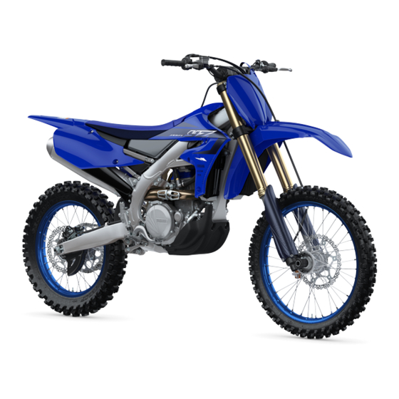
DESCRIPTION EAM20086 DESCRIPTION 2, 3 11.Fuel tank 1. Clutch lever 12.Radiator 2. Engine trouble warning light “ ” 13.Coolant drain bolt 3. Fuel level warning light “ ” 14.Rear brake pedal 4. Front brake lever 15.Air filter 5. Throttle grip 16.Drive chain 6. -
Page 18: Identification
There are two significant reasons for knowing the serial number of your vehicle: 1. When ordering parts, you can give the num- ber to your Yamaha dealer for positive identi- fication of the model you own. 2. If your vehicle is stolen, the authorities will need the number to search for and identify your vehicle. -
Page 19: Specifications
INCLUDED PARTS EAM20088 EWA20460 INCLUDED PARTS WARNING • Do not operate the engine in a closed area. EAM30005 The exhaust gas is poisonous. NIPPLE WRENCH • Never let flames near the servicing area. The nipple wrench “1” is used to tighten the spoke. - Page 20 INCLUDED PARTS pressed or while the engine is running (the CCU is activated), input the CCU serial num- ber into your smartphone and establish a wireless connection. 3. Activate the Power Tuner app. If the CCU wireless network cannot be detected, operate the start switch again.
-
Page 21: Important Information
YAMAHA genuine Refer to “CARE” on page 1-20. parts and recommended parts. -
Page 22: Instrument And Control Functions
” This warning light comes on or flashes if a prob- lem is detected in the electrical circuit monitoring the engine. If this occurs, have a Yamaha dealer check the vehicle. The electrical circuit of the warning light can be checked by pushing the start switch. -
Page 23: Shift Pedal
INSTRUMENT AND CONTROL FUNCTIONS You can use the Power Tuner app to adjust the map settings. When the mode switch “1” is illuminated, map 2 is selected. EAM30190 SIDESTAND This sidestand “1” is used to support only the machine when standing. EWA18980 WARNING •... -
Page 24: Fuel Tank Cap
INSTRUMENT AND CONTROL FUNCTIONS EAM30192 FUEL TANK CAP Fuel tank cap “1” is located under the fuel tank cap cover “2”. Remove the fuel tank cap cover to open the fuel tank cap. • To remove the fuel tank cap cover, insert fin- gers under part “a”, and then use both hands to lift it up towards the rear of the vehicle. -
Page 25: Starting And Break-In
(of 3000 to 5000 r/min), and then return the start- er knob to its original position. Your Yamaha engine has been designed to use unleaded gasoline with a pump octane number When operating the throttle grip in the closing di- [(R+M)/2] of 91 or higher, or a research octane rection, the starter knob “1”... -
Page 26: Starting A Warm Engine
STARTING AND BREAK-IN check the points shown in “TORQUE- CHECK POINTS” for tightening torques and retighten them. Also when the following parts are replaced, a break-in is required. • Cylinder and Crankshaft: A break-in is re- quired for about an hour. •... -
Page 27: Maintenance After Break-In
Pour the specified amount of the recom- AIR FILTER MAINTENANCE mended oil. Apply the Yamaha foam air filter oil or other qual- • Generator ity foam air filter oil to the element. (Excess oil in Check for looseness in mounted areas of the the element may adversely affect engine start- generator rotor and the stator coil assembly. -
Page 28: Torque-Check Points
TORQUE-CHECK POINTS EAM20125 TORQUE-CHECK POINTS Frame construction Combined seat and fuel tank Fuel tank to frame Frame to rear frame Frame to engine protector Engine mounting Frame to engine Engine bracket to engine Engine bracket to frame Seat Seat to frame Steering Steering stem to handlebar Steering stem to frame... - Page 29 TORQUE-CHECK POINTS Shift pedal Shift pedal to shift shaft Plastic cover Tightening of front fender Tightening of fork leg protector Tightening of air scoop Left cover to rear frame Tightening of side cover Tightening of rear fender Tightening of mud flap Tightening of rear brake disc cover Tightening of rear brake caliper cover...
- Page 30 MOTORCYCLE CARE AND STORAGE any longer than instructed. Also, thorough- EAM20126 MOTORCYCLE CARE AND STOR- ly rinse the area off with water, immediately dry it, and then apply a corrosion protec- tion spray. • Improper cleaning can damage plastic EAM30200 CARE parts (such as cowlings, panels, wind- While the open design of a motorcycle reveals...
- Page 31 Salt sprayed on roads in the winter may remain well into spring. • Consult a Yamaha dealer for advice on what 1. Clean the motorcycle with cold water and a products to use.
- Page 32 MOTORCYCLE CARE AND STORAGE stored. Long-term Before storing your motorcycle for several months: 1. Follow all the instructions in the “CARE” on page 1-20. 2. Fill up the fuel tank and add fuel stabilizer (if available) to prevent the fuel tank from rusting and the fuel from deteriorating.
- Page 33 SPECIFICATIONS GENERAL SPECIFICATIONS................2-1 ENGINE SPECIFICATIONS ................2-2 CHASSIS SPECIFICATIONS ................2-4 ELECTRICAL SPECIFICATIONS ..............2-6 TIGHTENING TORQUES .................2-7 GENERAL TIGHTENING TORQUE SPECIFICATIONS......2-7 ENGINE TIGHTENING TORQUES............2-8 CHASSIS TIGHTENING TORQUES............2-11...
-
Page 34: Specifications
GENERAL SPECIFICATIONS EAM20127 GENERAL SPECIFICATIONS Model Model BEXA (CAN) BEXB (AUS, NZL, ZAF) Dimensions Overall length 2175 mm (85.6 in) Overall width 825 mm (32.5 in) Overall height 1280 mm (50.4 in) Seat height 955 mm (37.6 in) Wheelbase 1480 mm (58.3 in) Ground clearance 320 mm (12.60 in) Weight... -
Page 35: Engine Specifications
ENGINE SPECIFICATIONS EAM20128 ENGINE SPECIFICATIONS Engine Combustion cycle 4-stroke Cooling system Liquid cooled Valve train DOHC Displacement 450 cm³ Number of cylinders Single cylinder Bore stroke 97.0 60.8 mm (3.82 2.39 in) Compression ratio 13.0 : 1 Starting system Electric starter Fuel... - Page 36 3.846 (50/13) Final drive Chain Air filter Air filter element Wet element Air filter oil grade Yamaha foam air filter oil or other quality foam air filter oil Idling condition Engine idling speed 1900–2100 r/min 70–80 C (158–176 F) Coolant temperature Throttle grip free play 3.0–6.0 mm (0.12–0.24 in)
-
Page 37: Chassis Specifications
Fork spring free length limit 492.0 mm (19.37 in) Inner tube bending limit 0.2 mm (0.01 in) Recommended oil Yamaha Suspension Oil S1 Quantity (left) 496.0 cm³ (16.77 US oz, 17.49 Imp.oz) Quantity (right) 496.0 cm³ (16.77 US oz, 17.49 Imp.oz) - Page 38 CHASSIS SPECIFICATIONS Compression damping Adjusting system Mechanical adjustable type Unit for compression damping adjustment Click Adjustment value from the start position (Soft) Adjustment value from the start position (STD) Adjustment value from the start position (Hard) Rear suspension Type Swingarm (link suspension) Spring Coil spring Shock absorber...
-
Page 39: Electrical Specifications
ELECTRICAL SPECIFICATIONS EAM20130 ELECTRICAL SPECIFICATIONS Battery Model BR98 Voltage, capacity 12 V, 2.4 Ah (5 HR) Indicator light Engine trouble warning light 1.7 W Fuel level warning light 1.7 W Fuse(s) Main fuse 15.0 A Radiator fan motor fuse 5.0 A Spare fuse 15.0 A... -
Page 40: Tightening Torques
TIGHTENING TORQUES EAM20131 TIGHTENING TORQUES EAM30205 GENERAL TIGHTENING TORQUE SPECIFICATIONS This chart specifies tightening torques for stan- dard fasteners with a standard ISO thread pitch. Tightening torque specifications for special com- ponents or assemblies are provided for each chapter of this manual. To avoid warpage, tight- en multi-fastener assemblies in a crisscross pat- tern and progressive stages until the specified tightening torque is reached. - Page 41 TIGHTENING TORQUES EAM30203 ENGINE TIGHTENING TORQUES - marked portion shall be checked for torque tightening after break-in or before each race. Thread Item Q’ty Tightening torques Remarks size Camshaft cap bolt 10 N·m (1.0 kgf·m, 7.4 lb·ft) Spark plug 13 N·m (1.3 kgf·m, 9.6 lb·ft) Cylinder head stud bolt (exhaust 7 N·m (0.7 kgf·m, 5.2 lb·ft) pipe)
- Page 42 TIGHTENING TORQUES Thread Item Q’ty Tightening torques Remarks size Clutch cable locknut (clutch cable 4.3 N·m (0.43 kgf·m, 3.2 lb·ft) adjuster) Clutch cable locknut (engine side) 7 N·m (0.7 kgf·m, 5.2 lb·ft) Exhaust pipe nut 10 N·m (1.0 kgf·m, 7.4 lb·ft) Exhaust pipe protector screw 10 N·m (1.0 kgf·m, 7.4 lb·ft) Exhaust pipe bracket bolt...
- Page 43 TIGHTENING TORQUES Thread Item Q’ty Tightening torques Remarks size Shift pedal bolt 12 N·m (1.2 kgf·m, 8.9 lb·ft) Generator rotor nut 65 N·m (6.5 kgf·m, 48 lb·ft) Stator coil screw 10 N·m (1.0 kgf·m, 7.4 lb·ft) Crankshaft position sensor bolt 10 N·m (1.0 kgf·m, 7.4 lb·ft) Stator coil assembly lead holder bolt 8 N·m (0.8 kgf·m, 5.9 lb·ft)
- Page 44 TIGHTENING TORQUES EAM30204 CHASSIS TIGHTENING TORQUES - marked portion shall be checked for torque tightening after break-in or before each race. Thread Item Q’ty Tightening torques Remarks size Upper bracket pinch bolt 21 N·m (2.1 kgf·m, 15 lb·ft) Lower bracket pinch bolt 21 N·m (2.1 kgf·m, 15 lb·ft) ...
- Page 45 TIGHTENING TORQUES Thread Item Q’ty Tightening torques Remarks size Front wheel axle pinch bolt 21 N·m (2.1 kgf·m, 15 lb·ft) Front brake disc bolt 12 N·m (1.2 kgf·m, 8.9 lb·ft) / Rear brake disc bolt 12 N·m (1.2 kgf·m, 8.9 lb·ft) / Footrest bracket bolt 55 N·m (5.5 kgf·m, 41 lb·ft)
- Page 46 TIGHTENING TORQUES Thread Item Q’ty Tightening torques Remarks size Drive chain tensioner bolt (lower 16 N·m (1.6 kgf·m, 12 lb·ft) side) Bolt (drive chain support) 7 N·m (0.7 kgf·m, 5.2 lb·ft) Drive chain support nut 7 N·m (0.7 kgf·m, 5.2 lb·ft) Drive chain guide bolt 4.0 N·m (0.40 kgf·m, 3.0 lb·ft) Fuel tank bolt (front side)
- Page 47 PERIODIC CHECKS AND ADJUSTMENTS MAINTENANCE INTERVALS................3-1 MAINTENANCE INTERVALS ..............3-1 PRE-OPERATION INSPECTION AND MAINTENANCE .........3-5 GENERAL INSPECTION AND MAINTENANCE........3-5 ENGINE ......................3-6 ADJUSTING THE VALVE CLEARANCE ...........3-6 CHECKING THE ENGINE IDLING SPEED ..........3-7 CHECKING THE THROTTLE GRIP............3-7 CHECKING THE SPARK PLUG ..............3-8 CHECKING THE ENGINE OIL LEVEL............3-9 CHANGING THE ENGINE OIL ..............3-9 ADJUSTING THE CLUTCH LEVER FREE PLAY........3-11...
- Page 48 CHECKING AND LUBRICATING THE CABLES ........3-29 LUBRICATING THE BRAKE LEVER ............3-30 LUBRICATING THE CLUTCH LEVER.............3-30 LUBRICATING THE PEDAL ..............3-30 CHECKING THE SIDESTAND..............3-30 LUBRICATING THE SIDESTAND............3-30 ELECTRICAL SYSTEM..................3-31 CHECKING AND CHARGING THE BATTERY........3-31 CHECKING THE FUSES .................3-31...
-
Page 49: Maintenance Intervals
(e.g., rain, dirt, etc.). Therefore, earlier inspection is required by reference to the list below. Items marked with an asterisk should be performed by a Yamaha dealer as they require special tools, data and technical skills. - Page 50 MAINTENANCE INTERVALS Every Every Every After race third race fifth race Item Routine break-in (about 2.5 (about 7.5 (about 12.5 required hours) hours) hours) • Check the coolant passages for corrosion. • Inspect carbon deposits and elim- 11 * Cylinder head inate them.
- Page 51 MAINTENANCE INTERVALS Every Every Every After race third race fifth race Item Routine break-in (about 2.5 (about 7.5 (about 12.5 required hours) hours) hours) • Clean. • Inspect and adjust. • Replace oil. 30 * Front fork leg(s) ...
- Page 52 MAINTENANCE INTERVALS Every Every Every After race third race fifth race Item Routine break-in (about 2.5 (about 7.5 (about 12.5 required hours) hours) hours) Brake pedal, footrest • Lubricate. Sidestand • Lubricate. Outside nuts and • Retighten. ...
-
Page 53: Pre-Operation Inspection And Maintenance
PRE-OPERATION INSPECTION AND MAINTENANCE EAM20134 PRE-OPERATION INSPECTION AND MAINTENANCE Before riding for break-in operation, practice or a race, make sure the machine is in good operating con- dition. Before using this machine, check the following points. EAM30209 GENERAL INSPECTION AND MAINTENANCE Item Inspect Page... -
Page 54: Engine
Turn the crankshaft counterclockwise with sic knowledge and skill concerning the servic- a wrench. ing of Yamaha motorcycles (e.g., Yamaha b. Align the top dead center (TDC) mark “a” dealers, service engineers, etc.). Those who on the generator rotor with the alignment have little knowledge and skill concerning ser- mark “b”... -
Page 55: Checking The Engine Idling Speed
1. Start the engine, and warm this up until the oil has reached the specified temperature. 2. Measure the coolant temperature using the Yamaha diagnostic tool. Yamaha diagnostic tool USB 90890-03267 Yamaha diagnostic tool (A/I) 90890-03264 FI diagnostic tool sub–lead... -
Page 56: Checking The Spark Plug
ENGINE 2. Adjust: 2. Remove: • Throttle grip free play • Spark plug cap • Spark plug a. Loosen the locknut “1”. b. Turn the adjuster “2” until the specified ECA24410 NOTICE throttle grip free play is obtained. In order not to allow the dirt accumulated c. -
Page 57: Checking The Engine Oil Level
ENGINE 7. Install: Recommended brand • Spark plug YAMALUBE SAE viscosity grades Spark plug 10W-40, 10W-50, 15W-40, 20W- 13 N·m (1.3 kgf·m, 9.6 lb·ft) 40 or 20W-50 Recommended engine oil grade API service SG type or higher, Before installing the spark plug, clean the spark JASO standard MA plug and gasket surface. - Page 58 ENGINE Oil strainer bolt 10 N·m (1.0 kgf·m, 7.4 lb·ft) 6. Install: • Gasket • Drain bolt Drain bolt 20 N·m (2.0 kgf·m, 15 lb·ft) 7. Pour the specified amount of engine oil into 4. If the oil filter element is also to be replaced, the oil filler cap hole.
-
Page 59: Adjusting The Clutch Lever Free Play
ENGINE a. Minimum level mark If the clutch lever free play cannot be obtained ECA26740 on the handlebar side, use the adjuster on the NOTICE clutch cable side. If the engine oil level does not decrease after the engine has been started, immediately Clutch cable side turn the engine off. -
Page 60: Cleaning The Air Filter Element
• Air filter element Damage Replace. 6. Apply: • Yamaha foam air filter oil or other quality foam air filter oil a. Put the air filter element into a plastic bag and drip the filter oil into the bag. -
Page 61: Checking The Throttle Body Joint
ENGINE 7. Install: 9. Install: • Seal “1” (to the air filter element) • Air filter case cover “1” • Guide “2” (to the air filter element) • Fuel tank breather hose • Air filter element “3” (to the air filter guide) (to the air filter case cover) •... -
Page 62: Checking The Fuel Line
ENGINE EAM30222 EAM30221 CHECKING THE FUEL LINE CHECKING THE EXHAUST SYSTEM 1. Remove: 1. Remove: • Seat • Exhaust pipe 1 • Side cover (left/right) • Exhaust pipe 2 • Air scoop (left/right) Refer to “EXHAUST SYSTEM” on page 5-1. •... - Page 63 ENGINE f. Install the silencer body “8” and bolts “9”. Silencer body bolt 8 N·m (0.8 kgf·m, 5.9 lb·ft) LOCTITE® Apply heat-resistant sealant to the areas “d” shown, making sure that there are no gaps in the beads of sealant. b.
-
Page 64: Checking The Coolant Level
ENGINE 7. Check: • Tightening torques Exhaust pipe nut “1” 10 N·m (1.0 kgf·m, 7.4 lb·ft) Exhaust pipe clamp bolt “2” 12 N·m (1.2 kgf·m, 8.9 lb·ft) Exhaust pipe clamp bolt “3” 12 N·m (1.2 kgf·m, 8.9 lb·ft) Silencer bolt (rear) “4” 30 N·m (3.0 kgf·m, 22 lb·ft) j. -
Page 65: Checking The Cooling System
ENGINE ator cap and turn it counterclockwise to re- • Side cover (left/right) move. • Air scoop (left/right) 2. Check: 1. Stand the vehicle upright on a level surface. • Radiator 2. Remove: • Radiator hose • Radiator cap “1” Crack/damage ... - Page 66 ENGINE 5. Install: • Copper washer • Coolant drain bolt Coolant drain bolt 10 N·m (1.0 kgf·m, 7.4 lb·ft) 6. Pour coolant. Recommended coolant High quality ethylene glycol anti-freeze containing anti-cor- rosion for aluminum engine Radiator (including all routes) 1.03 L (1.09 US qt, 0.91 Imp.qt) Coolant mixing ratio 1:1 (Coolant:Water) EWA13040...
-
Page 67: Chassis
CHASSIS system. Air in the brake system will consid- EAM20136 CHASSIS erably reduce braking performance. ECA13490 EAM30479 ADJUSTING THE FRONT DISC BRAKE NOTICE After adjusting the brake lever position, There should be no free play at the brake lever make sure there is no brake drag. end. -
Page 68: Checking The Front Brake Pads
CHASSIS Specified brake fluid DOT 4 EAM30232 CHECKING THE REAR BRAKE PADS The following procedure applies to all of the brake pads. A. Front brake 1. Operate the brake. B. Rear brake 2. Check: • Rear brake pad EWA13090 Wear indicator grooves “1” almost disap- WARNING •... -
Page 69: Checking The Brake Operation
CHASSIS 3. Hold the vehicle upright and apply the rear brake several times. 4. Check: • Brake hose Brake fluid leakage Replace the damaged hose. EAM30499 CHECKING THE BRAKE OPERATION 1. Check: • Brake operation Brake not working properly Check the brake system. -
Page 70: Drive Chain Slack
CHASSIS Bleed screw Drive chain slack (Maintenance 5 N·m (0.5 kgf·m, 3.7 lb·ft) Stand) 50.0–60.0 mm (1.97–2.36 in) j. Pour brake fluid to the reservoir up to the specified level. Adjusting the drive chain slack Refer to “CHECKING THE BRAKE FLUID EWA13120 WARNING LEVEL”... -
Page 71: Checking And Adjusting The Steering Head
CHASSIS clean the drive chain. Wipe the drive chain dry and thoroughly lubricate it with engine oil or chain lubricant that is suitable for O-ring chains. Do not use any other lubricants on the drive chain since they may contain solvents that could damage the O-rings. -
Page 72: Lubricating The Steering Head
Unsmooth operation Correct or replace. Refer to “FRONT FORK” on page 4-15. If any damage is found or the front fork does not operate smoothly, have a Yamaha dealer check or repair it. 5. Check: • Protector guide “1”... -
Page 73: Adjusting The Front Fork Legs
CHASSIS EAM30239 ADJUSTING THE FRONT FORK LEGS EWA19180 WARNING • Always adjust the left and right front forks evenly. If this is not done, the vehicle may have poor stability. • Securely support the vehicle so that there is no danger of it falling over. Rebound damping ECA24340 Compression damping... -
Page 74: Checking The Rear Shock Absorber Assembly
CHASSIS 3. Check: • Rear shock absorber assembly smooth ac- tion • Rear suspension link smooth action Sit astride the seat and shake your body up and down several times to check whether the rear shock absorber assembly operates smoothly. Unsmooth operation ... - Page 75 CHASSIS Spring preload adjusting positions Rebound damping Minimum Minimum (soft) Position in which the spring is 30 click(s) in direction “b”* turned in 1.5 mm (0.06 in) from Standard its free length. 8 click(s) in direction “b”* Standard Maximum (hard) Position in which the spring is 0 click(s) in direction “a”...
-
Page 76: Checking The Swingarm Operation
CHASSIS Fast compression damping Slow compression damping Minimum (soft) Minimum (soft) 2 turn(s) in direction “b”* 20 click(s) in direction “b”* Standard Standard 1-1/8 turn(s) in direction “b”* 10 click(s) in direction “b”* Maximum (hard) Maximum (hard) 0 turn(s) in direction “b”* 0 click(s) in direction “b”* * With the adjusting screw fully turned in di- * With the adjusting screw fully turned in di-... -
Page 77: Checking And Tightening The Spokes
CHASSIS Tire air pressure (measured on cold tires) Front 100 kPa (1.00 kgf/cm², 15 psi) Rear 100 kPa (1.00 kgf/cm², 15 psi) • Check the tire while it is cold. • Because if the bead stopper tightening nut is loose when the tire pressure is low, the tire could slip off the rim, thus be sure to check and Spoke nipple wrench (6–7) 90890-01521... - Page 78 CHASSIS place damaged outer cable and inner cables Recommended lubricant as soon as possible. Lithium-soap-based grease 1. Check: • Outer cable Damage Replace. 2. Check: • Cable operation Rough movement Lubricate. Recommended lubricant Engine oil or a suitable cable lu- bricant Hold the cable end upright and pour a few drops of lubricant into the cable sheath or use a suit-...
-
Page 79: Electrical System
ELECTRICAL SYSTEM EAM20137 ELECTRICAL SYSTEM EAM30256 CHECKING AND CHARGING THE BATTERY Refer to “CHECKING AND CHARGING THE BATTERY” on page 7-3. EAM30505 CHECKING THE FUSES Refer to “CHECKING THE FUSES” on page 7-3. 3-31... - Page 80 ELECTRICAL SYSTEM 3-32...
- Page 81 CHASSIS GENERAL CHASSIS..................4-1 REMOVING THE SEAT ................4-1 REMOVING THE NUMBER PLATE............4-1 INSTALLING THE AIR SCOOP ..............4-1 REMOVING THE SIDE COVER..............4-2 INSTALLING THE SIDE COVER ...............4-2 FRONT WHEEL....................4-3 REMOVING THE FRONT WHEEL.............4-3 INSTALLING THE FRONT WHEEL ............4-3 REAR WHEEL ....................4-4 REMOVING THE REAR WHEEL ...............4-4 CHECKING AND REPLACING THE REAR WHEEL SPROCKET ....4-4 INSTALLING THE REAR WHEEL..............4-4 FRONT BRAKE ....................4-6...
- Page 82 CHAIN DRIVE....................4-31 REMOVING THE DRIVE CHAIN..............4-31 CHECKING THE DRIVE CHAIN ..............4-31 CHECKING THE DRIVE SPROCKET............4-32 CHECKING THE REAR WHEEL SPROCKET.........4-32 INSTALLING THE DRIVE CHAIN ............4-32...
-
Page 83: General Chassis
GENERAL CHASSIS EAM20094 GENERAL CHASSIS EAM30016 REMOVING THE SEAT The fuel tank cap cover and the seat are coupled with each other with a plastic band. When removing the seat, always remove the fuel tank cap cover beforehand. 1. Remove: •... -
Page 84: Removing The Side Cover
GENERAL CHASSIS EAM30459 REMOVING THE SIDE COVER 1. Remove: • Side cover (right) “1” Remove the side cover (right) from the vehicle by removing the bolts and sliding it as shown. 1 1 1 a. Projection b. Slot EAM30460 INSTALLING THE SIDE COVER 1. -
Page 85: Front Wheel
FRONT WHEEL EAM20095 ECA24430 FRONT WHEEL NOTICE Before tightening the front wheel axle nut, EAM30017 push down hard on the handlebar(s) several REMOVING THE FRONT WHEEL times and check if the front fork rebounds 1. Use a maintenance stand to raise the front smoothly. -
Page 86: Rear Wheel
REAR WHEEL EAM20096 REAR WHEEL EAM30022 REMOVING THE REAR WHEEL 1. Use a maintenance stand to raise the rear wheel off the ground. EWA13120 WARNING Securely support the vehicle so that there is no danger of it falling over. 2. Remove: b. - Page 87 REAR WHEEL drive chain. Drive chain slack (Maintenance Stand) 50.0–60.0 mm (1.97–2.36 in) Refer to “DRIVE CHAIN SLACK” on page 3-22. 3. Install: • Drive chain puller (left) “1” • Rear wheel axle “2” • Install the drive chain puller (left), and insert the 6.
-
Page 88: Front Brake
FRONT BRAKE EAM20097 FRONT BRAKE Brake pad lining thickness limit 1.0 mm (0.04 in) EAM30519 REPLACING THE FRONT BRAKE PADS When replacing the brake pads, it is not neces- sary to disconnect the brake hose or disassem- ble the brake caliper. 1. - Page 89 FRONT BRAKE e. Install the brake caliper “4” and tighten the pad pin “5”. Bolt (brake caliper) 28 N·m (2.8 kgf·m, 21 lb·ft) Pad pin 17 N·m (1.7 kgf·m, 13 lb·ft) f. Install the pad pin plug “6”. Pad pin plug 2.5 N·m (0.25 kgf·m, 1.8 lb·ft) 4.
-
Page 90: Rear Brake
REAR BRAKE EAM20098 REAR BRAKE Brake pad lining thickness limit 1.0 mm (0.04 in) EAM30523 REPLACING THE REAR BRAKE PADS When replacing the brake pads, it is not neces- sary to disconnect the brake hose or disassem- ble the brake caliper. 1. - Page 91 REAR BRAKE Refer to “BLEEDING THE HYDRAULIC BRAKE SYSTEM” on page 3-21. e. Install the brake caliper “5” and the rear wheel “6”. f. Tighten the pad pin “7”. Pad pin 17 N·m (1.7 kgf·m, 13 lb·ft) g. Install the pad pin plug “8” and the protector “9”.
-
Page 92: Handlebar
HANDLEBAR EAM20099 EAM30054 HANDLEBAR INSTALLING THE HANDLEBAR 1. Stand the vehicle upright on a level surface. EAM30052 EWA13120 REMOVING THE HANDLEBAR WARNING 1. Stand the vehicle upright on a level surface. Securely support the vehicle so that there is EWA13120 no danger of it falling over. - Page 93 HANDLEBAR 3. Tighten: • Lower handlebar holder nut Lower handlebar holder nut 40 N·m (4.0 kgf·m, 30 lb·ft) 4. Install: • Clutch lever holder “1” • Clutch lever “2” Clutch lever holder bolt 5 N·m (0.5 kgf·m, 3.7 lb·ft) Clutch lever nut 4.0 N·m (0.40 kgf·m, 3.0 lb·ft) The clutch lever holder “1”...
- Page 94 HANDLEBAR 6. Install: quer thinner. • Handlebar grip “1” • Install the grip to the tube guide so that the grip a. Slightly coat the handlebar left end with a match mark “b” and tube guide slot “c” form the rubber adhesive.
- Page 95 HANDLEBAR 12.Install: 14.Install: • Throttle cable housing “1” • Start switch “1” • Screw (throttle cable housing) “2” • Front brake master cylinder assembly “2” • Front brake master cylinder holder “3” Screw (throttle cable housing) • Front brake master cylinder holder bolt “4” 3.8 N·m (0.38 kgf·m, 2.8 lb·ft) •...
- Page 96 HANDLEBAR Throttle grip free play 3.0–6.0 mm (0.12–0.24 in) 4-14...
-
Page 97: Front Fork
FRONT FORK EAM20100 FRONT FORK EAM30055 REMOVING THE FRONT FORK LEGS 1. Use a maintenance stand to raise the front wheel off the ground. EWA13120 WARNING Securely support the vehicle so that there is no danger of it falling over. Record the adjusting screw setting position be- fore loosening the adjuster and the base valve. -
Page 98: Checking The Front Fork Legs
FRONT FORK Cap bolt wrench 90890-01500 Cap bolt wrench YM-01500 Cap bolt ring wrench 90890-01501 Cap bolt ring wrench YM-01501 3. Remove: • Dust seal “1” • Stopper ring “2” (with a flat-head screwdriver) ECA14180 NOTICE Do not scratch the inner tube. EAM30057 CHECKING THE FRONT FORK LEGS 1. - Page 99 FRONT FORK 4. Check: 6. Check: • Damper assembly “1” • Upper spring seat “1” Bend/damage Replace. (contacting surface “a”) Wear/damage Replace. • O-ring “2” Wear/damage Replace. ECA14200 NOTICE • The front fork leg has a built-in damper ad- justing rod and a very sophisticated inter- nal construction, which are particularly sensitive to foreign material.
-
Page 100: Assembling The Front Fork Legs
1. Stretch the damper assembly fully. 2. Fill: • Damper assembly Recommended oil Yamaha Suspension Oil S1 Standard oil amount 216 cm³ (7.30 US oz, 7.62 Imp.oz) ECA24530 NOTICE • Be sure to use the recommended oil. Other oils may have an adverse effect on front 5. - Page 101 FRONT FORK obtained after installation. 10.After filling, pump the damper assembly “1” slowly up and down more than 10 times to 7. Install: distribute the fork oil. • Base valve “1” (to the damper assembly “2”) First bring the damper rod pressure to a maxi- mum.
- Page 102 FRONT FORK 13.Check: • Damper assembly smooth movement Tightness/binding/rough spots Repeat the steps (1) to (12). 15.Install: • Piston metal “1” Install the piston metal onto the slot on inner 14.Install: tube. • Dust seal “1” • Scraper “2” •...
- Page 103 FRONT FORK (to the outer tube) 19.Install: • Stopper ring “1” Press the slide metal into the outer tube with fork seal driver “3”. Fit the stopper ring correctly in the groove in the outer tube. Fork seal driver 90890-01502 Fork seal driver (48) YM-A0948 20.Install:...
- Page 104 FRONT FORK Distance “a” 16 mm (0.63 in) or more Between the damper assembly “1” bottom and locknut “2” bot- tom. 25.Loosen: • Rebound damping force adjuster “1” • Before loosening the damping force adjuster, record the setting position. • Unless the damping force adjuster is fully loos- ened, correct damping characteristic cannot be 23.Install: obtained after installation.
- Page 105 0.5–1.0 mm (0.02–0.04 in) 30.Fill: • Front fork leg Recommended oil If it is installed with a gap out of specification, Yamaha Suspension Oil S1 correct damping force cannot be obtained. Standard oil amount 290 cm³ (9.80 US oz, 10.23 Imp.oz) Extent of adjustment 260–365 cm³...
-
Page 106: Installing The Front Fork Legs
FRONT FORK Cap bolt ring wrench 90890-01501 Cap bolt ring wrench YM-01501 32.Install: • Protector guide “1” EAM30059 INSTALLING THE FRONT FORK LEGS 1. Install: 3. Adjust: • Front fork “1” • Front fork top end “a” • Temporarily tighten the lower bracket pinch Front fork top end (standard) “a”... - Page 107 FRONT FORK 8. Adjust: Lower bracket pinch bolt • Compression damping force 21 N·m (2.1 kgf·m, 15 lb·ft) Turn in the damping adjuster “1” finger-tight and EWA19320 then turn out to the originally set position. WARNING Tighten the lower bracket to specified torque.
-
Page 108: Steering Head
STEERING HEAD c. Install a new bearing race. EAM20101 STEERING HEAD ECA14270 NOTICE EAM30060 If the bearing race is not installed properly, REMOVING THE LOWER BRACKET the steering head pipe could be damaged. 1. Use a maintenance stand to raise the front wheel off the ground. - Page 109 STEERING HEAD 2. Install: • Bearing race • Upper bearing “1” • Bearing race cover “2” Apply the lithium-soap-based grease on the bearing and bearing race cover lip. 5. Check the steering stem by turning this lock to lock. If there is any binding, remove the steering stem and check the steering bear- ing.
- Page 110 STEERING HEAD Upper bracket pinch bolt 21 N·m (2.1 kgf·m, 15 lb·ft) • Lower bracket pinch bolt “2” Lower bracket pinch bolt 21 N·m (2.1 kgf·m, 15 lb·ft) EWA19330 WARNING Tighten the lower bracket to specified 8. Install: torque. If torqued too much, it may cause the •...
-
Page 111: Rear Shock Absorber Assembly
REAR SHOCK ABSORBER ASSEMBLY absorber assembly. EAM20102 REAR SHOCK ABSORBER AS- • Spring SEMBLY Damage/wear Replace. • Spring guide Damage/wear Replace. EAM30065 REMOVING THE REAR SHOCK ABSORBER • Bearing ASSEMBLY Damage/wear Replace. 1. Use a maintenance stand to raise the rear •... -
Page 112: Swingarm
SWINGARM EAM20103 SWINGARM EAM30071 REMOVING THE SWINGARM 1. Use a maintenance stand to raise the rear wheel off the ground. EWA13120 WARNING Securely support the vehicle so that there is no danger of it falling over. 2. Measure: • Swingarm side play •... -
Page 113: Chain Drive
CHAIN DRIVE EAM20104 CHAIN DRIVE EAM30075 REMOVING THE DRIVE CHAIN 1. Stand the vehicle on a level surface. EWA13120 WARNING Securely support the vehicle so that there is no danger of it falling over. Place the vehicle on a maintenance stand so that the rear wheel is elevated. -
Page 114: Checking The Drive Sprocket
CHAIN DRIVE b. Correct 1. Drive chain roller 2. Drive sprocket EAM30078 CHECKING THE REAR WHEEL SPROCKET Refer to “CHECKING AND REPLACING THE REAR WHEEL SPROCKET” on page 4-4. EAM30079 INSTALLING THE DRIVE CHAIN 1. Install: 4. Check: • Drive chain •... - Page 115 CHAIN DRIVE ECA24590 NOTICE A drive chain that is too tight will overload the engine and other vital parts, and one that is too loose can skip and damage the swing- arm or cause an accident. Therefore, keep the drive chain slack within the specified lim- its.
- Page 116 CHAIN DRIVE 4-34...
- Page 117 ENGINE EXHAUST SYSTEM ..................5-1 INSTALLING THE EXHAUST PIPE AND MUFFLER.........5-1 CLUTCH ......................5-2 REMOVING THE CLUTCH ................5-2 CHECKING THE FRICTION PLATES............5-2 CHECKING THE CLUTCH PLATES ............5-2 CHECKING THE CLUTCH SPRINGS............5-2 CHECKING THE CLUTCH HOUSING ............5-2 CHECKING THE CLUTCH BOSS..............5-3 CHECKING THE PRESSURE PLATE ............5-3 CHECKING THE PUSH LEVER SHAFT............5-3 CHECKING THE PUSH RODS ..............5-3 CHECKING THE PRIMARY DRIVE GEAR..........5-3...
-
Page 118: Exhaust System
EXHAUST SYSTEM EAM20199 EXHAUST SYSTEM EAM30167 INSTALLING THE EXHAUST PIPE AND MUFFLER 1. Install: • Gasket • Exhaust pipe 1 “1” • Nut (exhaust pipe 1) “2” Nut (exhaust pipe 1) 10 N·m (1.0 kgf·m, 7.4 lb·ft) A. Exhaust pipe 1 and exhaust pipe 2 B. -
Page 119: Clutch
CLUTCH Damage Replace the clutch plates as a EAM20111 CLUTCH set. 2. Measure: EAM30108 • Clutch plate warpage REMOVING THE CLUTCH (with a surface plate and thickness gauge) 1. Remove: Out of specification Replace the clutch • Clutch boss nut “1” plates as a set. -
Page 120: Checking The Clutch Boss
CLUTCH EAM30113 CHECKING THE CLUTCH BOSS 1. Check: • Clutch boss splines Damage/pitting/wear Replace the clutch 1 1 1 boss. Pitting on the clutch boss splines will cause er- ratic clutch operation. 2. Measure: • Push rod 2 bending limit Out of specification ... - Page 121 CLUTCH 2. Install: • Dowel pin “1” • O-ring “2” • Collar “3” • Gasket “4” Apply the lithium-soap-based grease on the O- ring. 4. Install: • Push lever shaft “1” • Apply the lithium-soap-based grease on the oil seal lip. •...
- Page 122 CLUTCH 1 1 1 8. Install: 6. Install: • Friction plate 1 “1” • Lock washer “1” • Clutch plate “2” • Clutch boss nut “2” • Friction plate 2 “3” Clutch boss nut 75 N·m (7.5 kgf·m, 55 lb·ft) •...
- Page 123 CLUTCH 13.Install: • O-ring “1” Apply the lithium-soap-based grease to the O- ring. 10.Install: • Push rod 2 “1” • Ball “2” • Push rod 1 “3” Apply the engine oil on the push rod 1, 2 and 14.Install: ball. •...
- Page 124 CLUTCH...
- Page 125 FUEL SYSTEM FUEL TANK ......................6-1 REMOVING THE FUEL TANK ..............6-1 INSTALLING THE FUEL TANK..............6-1...
- Page 126 FUEL TANK EAM20140 FUEL TANK EAM30263 REMOVING THE FUEL TANK 1. Extract the fuel in the fuel tank through the fuel tank cap with a pump. 2. Remove: • Fuel hose coupler EWA19370 WARNING Cover the fuel hose connection with a cloth when disconnecting it.
- Page 127 FUEL TANK 3. Connect: • Fuel pump coupler 4. Install: • Air scoop (left/right) • Seat • Side cover (left/right) Refer to “GENERAL CHASSIS” on page 4-1.
- Page 128 FUEL TANK...
- Page 129 ELECTRICAL SYSTEM FUEL INJECTION SYSTEM................7-1 ECU SELF-DIAGNOSTIC FUNCTION............7-1 ELECTRICAL COMPONENTS.................7-3 CHECKING THE FUSES ................7-3 CHECKING AND CHARGING THE BATTERY..........7-3...
- Page 130 FUEL INJECTION SYSTEM EAM20145 FUEL INJECTION SYSTEM EAM30352 ECU SELF-DIAGNOSTIC FUNCTION The ECU is equipped with a self-diagnostic function in order to ensure that the fuel injection system is operating normally. If this function detects a malfunction in the system, it immediately operates the en- gine under substitute characteristics and illuminates the engine trouble warning light to alert the rider that a malfunction has occurred in the system.
- Page 131 FUEL INJECTION SYSTEM ECU detects an abnormal signal from a sensor If the ECU detects an abnormal signal from a sensor while the vehicle is being driven, the ECU illumi- nates the engine trouble warning light and provides the engine with alternate operating instructions that are appropriate for the type of malfunction.
- Page 132 ELECTRICAL COMPONENTS a Yamaha dealer check the electrical sys- EAM20147 ELECTRICAL COMPONENTS tem. Amperage EAM30290 Fuses Q’ty CHECKING THE FUSES rating The following procedure applies to all of the fus- Main 15 A 1. Remove: Spare 15 A • Seat Radiator fan motor Refer to “GENERAL CHASSIS”...
- Page 133 When Refer to “GENERAL CHASSIS” on page 4-1. replacing the battery, be sure to use a 2. Disconnect: Yamaha genuine lithium-ion battery. • Battery lead (from the battery terminals) Do not check the battery at high temperature of ECA13700 65 C (149 F) or more or low temperatures be-...
- Page 134 ELECTRICAL COMPONENTS Checking is finished. Less than 13.25 V Go to step (c). c. Connect the battery charger (special tool) to the battery and charge it. Lithium battery charger 90890-05376 Lithium battery charger DBY-ACC51-70-02 For instructions on charging and handling the battery charger, refer to the battery charger’s in- struction manual.
-
Page 135: Troubleshooting
TROUBLESHOOTING TROUBLESHOOTING..................8-1 GENERAL INFORMATION ................8-1 TROUBLESHOOTING OF ENGINE (fault code not detected)....8-1 TROUBLESHOOTING OF CLUTCH............8-4 TROUBLESHOOTING OF TRANSMISSION ..........8-6 TROUBLESHOOTING OF COOLING SYSTEM ........8-7 TROUBLESHOOTING OF BRAKE ............8-8 TROUBLESHOOTING OF SUSPENSION..........8-8 TROUBLESHOOTING OF STEERING/HANDLING ........8-10 TROUBLESHOOTING OF CHARGING SYSTEM ........8-11 TROUBLESHOOTING OF SIGNALING SYSTEM ........8-11 SELF-DIAGNOSTIC FUNCTION AND DIAGNOSTIC CODE TABLE ...8-12 SELF-DIAGNOSTIC FUNCTION TABLE (FOR FUEL INJECTION... -
Page 136: Troubleshooting
• The following guide for troubleshooting represent quick and easy procedures for checking these vital systems yourself. However, should your motorcycle require any repair, take it to a Yamaha dealer, whose skilled technicians have the necessary tools, experience, and know-how to service the motor- cycle properly. - Page 137 Low fuel pressure Clogged fuel pump Clean or replace the fuel pump. Cracks or damage in fuel pump Replace the fuel pump. Have a Yamaha dealer check the Fuel pump malfunction electrical system. Failed or clogged fuel injector Replace the fuel injector.
- Page 138 TROUBLESHOOTING Symptom Possible cause Actions Worn camshaft lobe Replace the camshaft. Water or foreign material in fuel, Change fuel. degraded fuel Contaminated throttle body or Clean the throttle body. clogged internal passage Incorrectly adjusted throttle cable Adjust the throttle grip free play. Incorrectly adjusted idling speed Adjust the idle screw.
-
Page 139: Troubleshooting Of Clutch
TROUBLESHOOTING Symptom Possible cause Actions Replace the piston and piston Worn or damaged piston ring rings as a set. Replace the piston and piston Worn or damaged piston rings as a set. Replace the piston and piston pin Worn piston (piston pin hole) as a set. - Page 140 TROUBLESHOOTING Symptom Possible cause Actions Replace the clutch springs as a Faulty clutch spring set. Warped pressure plate Replace the pressure plate. Replace the friction plates as a Swollen friction plate set. Warped clutch plate Replace the clutch plates as a set. Bent pull rod (outer pull type) Replace the pull rod.
-
Page 141: Troubleshooting Of Transmission
TROUBLESHOOTING EAM30511 TROUBLESHOOTING OF TRANSMISSION Symptom Possible cause Actions Clutch drags Refer to “Clutch drags”. Adjust the shift rod installation Improperly adjusted shift rod length. Bent shift shaft Replace the shift shaft. Foreign object in a shift drum Remove foreign object from shift groove drum groove. -
Page 142: Troubleshooting Of Cooling System
TROUBLESHOOTING EAM30512 TROUBLESHOOTING OF COOLING SYSTEM Symptom Possible cause Actions Carbon buildup in piston head and Clean the piston head and com- combustion chamber bustion chamber. Clogged engine cooling water Check and clean the engine cool- passages ing water passages. Adjust the oil level to the specified Incorrect oil level level. -
Page 143: Troubleshooting Of Brake
TROUBLESHOOTING EAM30513 TROUBLESHOOTING OF BRAKE Symptom Possible cause Actions Worn brake pad Replace the brake pads as a set. Worn or deflected brake disc Replace the brake disc. Air in hydraulic brake system Bleed the hydraulic brake system. Check the hydraulic brake system Brake fluid leakage and repair or replace faulty parts as necessary. - Page 144 TROUBLESHOOTING Symptom Possible cause Actions Fatigued or broken fork spring Replace the fork spring. Incorrect oil viscosity (low) Change to recommended fork oil. Incorrect oil level (low) Adjust to the specified oil level. Improperly adjusted spring pre- Adjust the spring preload. Front fork is soft load (soft) Improperly adjusted rebound...
-
Page 145: Troubleshooting Of Steering/Handling
TROUBLESHOOTING Symptom Possible cause Actions Oil leaking from rear shock Replace the rear shock absorber. absorber Gas leaking from rear shock Replace the rear shock absorber. absorber Fatigued or damaged rear shock Replace the rear shock absorber. absorber spring Rear suspension is soft Improperly adjusted rear shock Adjust the spring preload. -
Page 146: Troubleshooting Of Charging System
EAM30516 TROUBLESHOOTING OF CHARGING SYSTEM Symptom Possible cause Actions Battery is not charged Have a Yamaha dealer check the electrical system. EAM30521 TROUBLESHOOTING OF SIGNALING SYSTEM Symptom Possible cause Actions Indicator lights do not come on Have a Yamaha dealer check the electrical system. -
Page 147: Self-Diagnostic Function And Diagnostic Code Table
SELF-DIAGNOSTIC FUNCTION AND DIAGNOSTIC CODE TABLE EAM20174 SELF-DIAGNOSTIC FUNCTION AND DIAGNOSTIC CODE TABLE EAM30497 SELF-DIAGNOSTIC FUNCTION TABLE (FOR FUEL INJECTION SYSTEM) Fault code Item Crankshaft position sensor: no normal signals are received from the crankshaft position sen- sor. Intake air pressure sensor: open or short circuit detected. Intake air pressure sensor: hose system malfunction (clogged or detached hose). - Page 148 SELF-DIAGNOSTIC FUNCTION AND DIAGNOSTIC CODE TABLE 8-13...
-
Page 149: Tuning
TUNING CHASSIS ......................9-1 SELECTION OF THE SECONDARY REDUCTION RATIO (SPROCKET) ....................9-1 DRIVE AND REAR WHEEL SPROCKETS SETTING PARTS ....9-1 TIRE PRESSURE..................9-1 FRONT FORK SETTING................9-2 CHANGE IN AMOUNT AND CHARACTERISTICS OF FORK OIL....9-2 SETTING OF SPRING AFTER REPLACEMENT ........9-2 FRONT FORK SETTING PARTS...............9-3 REAR SUSPENSION SETTING ..............9-3 CHOOSING SET LENGTH ................9-3 SETTING OF SPRING AFTER REPLACEMENT ........9-4... -
Page 150: Chassis
CHASSIS EAM20119 EAM30169 CHASSIS DRIVE AND REAR WHEEL SPROCKETS SETTING PARTS EAM30168 SELECTION OF THE SECONDARY Part name Type Part number REDUCTION RATIO (SPROCKET) Drive (STD) 9383E-13233 sprocket “1” Secondary reduction ratio = Number of rear wheel sprocket teeth/Number of Rear wheel 17D-25447-50 sprocket “2”... -
Page 151: Front Fork Setting
Turn out one or two clicks. • Change the compression damping force. Recommended oil Turn in one or two clicks. Yamaha Suspension Oil S1 Standard oil amount 290 cm³ (9.80 US oz, 10.23 Generally a soft spring gives a soft riding feeling. -
Page 152: Front Fork Setting Parts
CHASSIS Generally a stiff spring gives a stiff riding feeling. Rebound damping tends to become weaker, re- sulting in lack of a sense of contact with the road surface or in a vibrating handlebar. EAM30174 FRONT FORK SETTING PARTS • Front fork spring STD Spring rate N/mm 2. -
Page 153: Setting Of Spring After Replacement
CHASSIS EAM30177 EAM30178 SETTING OF SPRING AFTER REAR SHOCK ABSORBER SETTING PARTS REPLACEMENT • Rear shock spring “1” After replacement, be sure to adjust the spring to STD Spring rate the set length [sunken length 90–100 mm (3.5– N/mm 3.9 in)] and set it. Spring 1. - Page 154 CHASSIS • Spring preload adjusting positions Spring preload adjusting positions Minimum Position in which the spring is turned in 1.5 mm (0.06 in) from its free length. Standard Position in which the spring is turned in 10.0 mm (0.39 in) from its free length.
-
Page 155: Suspension Setting (Front Fork)
CHASSIS EAM30179 SUSPENSION SETTING (FRONT FORK) • If any of the following symptoms is experienced with the standard position as the base, make resetting by reference to the adjustment procedure given in the same chart. • Before any change, set the rear shock absorber sunken length to the standard figure 90–100 mm (3.5–3.9 in). -
Page 156: Suspension Setting (Rear Shock Absorber)
CHASSIS Section Symptom Check Adjust Large Medium Small Jump Compression Turn adjuster clockwise (about 2 damping force clicks) to increase damping. Turn adjuster counterclockwise Rebound damp- (about 2 clicks) to decrease ing force damping. Low front, tend- ing to lower front Set sunken length for 95–100 posture Balance with rear... - Page 157 CHASSIS Section Symptom Check Adjust Large Medium Small Jump Turn adjuster counterclockwise Rebound damp- (about 2 clicks) to decrease Heavy and drag- ing force damping. ging Spring Replace with soft spring. Turn adjuster counterclockwise Rebound damp- (about 2 clicks) to decrease ing force damping.
- Page 158 CHASSIS...
- Page 159 15. Warning light Green/White 16. Fuel level warning light Green/Yellow 17. Engine trouble warning light Blue/Black 18. Resistor Blue/Green 19. Yamaha diagnostic tool cou- Blue/Red pler Blue/White 20. ECU (Engine Control Unit) Blue/Yellow 21. Ignition coil Pink/Black 22. Spark plug Pink/Blue 23.
- Page 160 PRINTED IN JAPAN...
- Page 162 PRINTED IN JAPAN 2022.06-0.1×1 ! (E, F)
- Page 163 YZ450FXP 2023 YZ450FXP 2023 SCHÉMA DE CÂBLAGE WIRING DIAGRAM...
- Page 164 YZ450FXP 2023 YZ450FXP 2023 SCHÉMA DE CÂBLAGE WIRING DIAGRAM...
Need help?
Do you have a question about the YZ450FX 2023 and is the answer not in the manual?
Questions and answers