Ancona UCT630 User's Manual & Installation Instructions
Hide thumbs
Also See for UCT630:
- User manual and installation instructions (22 pages) ,
- User manual and installation instructions (22 pages)
Table of Contents
Advertisement
Quick Links
Advertisement
Table of Contents

Related Manuals for Ancona UCT630


Summary of Contents for Ancona UCT630
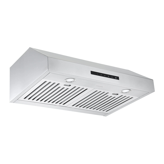
- Page 1 Range Hood UCT630 and UCT636 User Manual & Installation Instructions IMPORTANT SAFETY INSTRUCTIONS Carefully read the important information regarding installation, safety and maintenance. Keep these instructions for future reference. MAAN1201-01 2018-08-01...
-
Page 2: Before You Begin
Before You Begin INSTALLERS - Start Here Safety Instructions are on pages 4 and 5 and Installation Instructions are on pages 8 to 13. Please perform these steps: 1. Read the safety instructions. 2. Read all instructions in the Installation section of this manual BEFORE installing the range hood. -
Page 3: Table Of Contents
Table of Contents Before You Begin ..........................2 Table of Contents ..........................3 Important Safety Information ......................4 Included Parts ........................... 6 Range Hood Dimensions ........................7 Specifications ............................ 7 Installation ............................8 Step 1 - Read the Safety Instructions .................... 8 Step 2 - Unpack Range Hood and Prepare Tools ................ -
Page 4: Important Safety Information
Important Safety Information READ ALL INSTRUCTIONS BEFORE USE Read and follow all instructions before using the range hood to prevent the risk of fire, electric shock, personal injury, or damage when using the range hood or appliances with the range hood. This guide does not cover all possible conditions that may occur. - Page 5 Important Safety Information WARNING: TO REDUCE RISK OF A RANGE To reduce the risk of injury to persons in the TOP GREASE FIRE: event of a gas leaks: a) Never leave surface units unattended at high • Extinguish any open flame. settings. Boilovers cause smoking and greasy • DO NOT turn on the lights or any type of appliance.
-
Page 6: Included Parts
Included Parts Range Hood Damper flap 2 x Filters (30 in.) 3 x Filters (36 in.) Hardware Note: For safety reasons, range hood mounting screws and anchors will not be included due to the variation of cabinetry constructions and wall material. Please consult your installation specialist regarding the optimal type of mounting screws and wall anchors to suit your home’s construction. -
Page 7: Range Hood Dimensions
Range Hood Dimensions Ø 5.9 in. (15 cm) 12 in. (30.5 cm) 3.1 in. (8 cm) 9.6 in. (24.6 cm) 29.7 in. (75.5 cm) / 35.4 in. (90 cm) 20.6 in. (52.5 cm) Specifications Body Design Stainless Steel Power Rating 120 V / 60 Hz (cULus Certified) Total Input Power 405 W (400 W + 2 x 2.5 W) -
Page 8: Installation
Installation STEP 1 Read the Safety Instructions • It is very important to read the safety instructions on pages 4 and 5. IMPORTANT: It is the installer’s responsibility to comply with installation clearances. STEP 2 Unpack Range Hood and Prepare Tools • Carefully unpack the range hood and parts. -
Page 9: Step 5 - Venting Installation Guidelines
Installation STEP 5 Venting Installation Guidelines • The following steps are for exterior ventilation. IMPORTANT: For the most efficient and quiet operation: • Vent system must terminate to the outside (roof or side wall). • It is recommended that the range hood be vented • DO NOT terminate the vent system in an attic or other vertically through the roof through 6 in. - Page 10 Installation IMPORTANT: electric cook tops and minimum of 30-inch (76.2 cm) • A minimum of 6 in. (15.3 cm) round or 3-1/4 x 10 in. (25.4 for gas stove tops and no higher than 30-inch (76.2 cm) cm x 8.3 cm) rectangular duct must be used to maintain for electric cook tops.
-
Page 11: Step 6 - Preparations
Installation STEP 6 Preparations NOTE: To avoid damage to your hood, prevent debris from entering the vent opening. • Determine and mark the centre line on the ceiling or wall where the range hood will be installed. • Make sure there is proper clearance within the ceiling or wall for exhaust vent. • Due to the weight and size of this unit, please make sure that the support system or framework being used is stable and secure in the ceiling or wall. -
Page 12: Step 9 - Attaching The Unit Under The Kitchen Cabinets
Installation STEP 9 Attaching the unit under the kitchen cabinets • Mark or drill a small hole on the mounting position according to the space and dimensions cited on the following drawings. • Attach the range hood under the kitchen cabinets and ducting to the top round 6 in. damper and exhaust outdoors. • The following drawings show the mounting dimensions of the 30 in. -
Page 13: Step 10 - Install Filters
Installation STEP 10 Install Filters To install filters, follow four steps below (See Fig #4): • Angle the filter into slots at the back of the hood. • Push the button on handle of the filter. • Release the handle once the filter fits into a resting position. • Repeat to install all filters. -
Page 14: Operation
056B 056B 056B 056B Operation 056B 056B 056B 056B 056B 056B 013B 056B 056B 056B 056B 013B 013B 056B 056B 056B 056B Decrease Increase Lamp Timer Power 013B 013B 013B 056B 056B 056B Speed Speed 013B 056B 056B 056B 056B 056B NOTE: When the hood has been initially connected to the 056B... -
Page 15: Maintenance
Maintenance Replacing the Light Pucks IMPORTANT: ALWAYS SWITCH OFF THE ELECTRICITY SUPPLY AT THE MAIN PANEL BEFORE CARRYING OUT ANY OPERATION ON THE APPLIANCE. Make sure the range hood is unplugged or turn OFF breaker. Replace with a 10.2 Volt, 2.5 Watt max, LED lights. Plug in new puck and push back into light panel. -
Page 16: Range Hood Assembly
Range Hood Assembly Number Part Power cord Damper flap Housing assembly Cover of control box Control board Base of electronic box Capacitor Cover of electronic box Blower assembly (includes motor) Light Panel LED lights Baffle filter (2 or 3 pcs) Screw bag —... -
Page 17: Assembly
Assembly Circuit Diagram Motor 0V 60Hz Capacitor Main PCB _ _ _ LED Pucks CH B MAX 10.2V 250mA 2.5W Temperature / Humidity Sensor (Optional) Blower Assembly Number Part Left blower housing Impeller Motor Right blower housing Electrical Assembly Number Part Junction box cover Capacitor... -
Page 18: Troubleshooting
Troubleshooting Problem Possible Cause If the range hood or LED light Check if the range hood has been plugged in, make sure that all power does not operate after installation: has been turned back ON, fused not blown and all electrical wiring are properly connected. -
Page 19: Use And Care Information
Use and Care Information Operations • Read and understand all instructions and warnings in this manual before operating the appliance. Save these instructions for future reference. • Always leave safety grills and filters in place. Without these components, operating fans could catch on to hair, fingers and loose clothing. - Page 20 Ancona is in association with Mr Appliance for all after sales service calls. Please contact their service provider or visit their website: Phone: 1-888-998-2011 Website: www.mrappliance.com MAAN1201-01 © 2018 Copyright of Ancona Home. All rights reserved. This material may not be reproduced, displayed, modified or distributed. — 20 —...
Need help?
Do you have a question about the UCT630 and is the answer not in the manual?
Questions and answers