Table of Contents
Advertisement
QQ
3 7 63 1515 0
SERVICE MANUAL
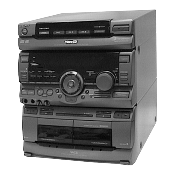
HCD-V808 is the tuner, deck, Video CD and
amplifier section in MHC-V808.
* Dolby noise reduction manufactured
under license from Dolby Laboratories
Licensing Corporation.
"DOLBY" and the double-D symbol a
are trademarks of Dolby Laboratories
Licensing Corporation.
TE
L 13942296513
www
.
MICROFILM
http://www.xiaoyu163.com
x
ao
u163
y
i
http://www.xiaoyu163.com
HCD-V808
2 9
8
Model Name Using Similar Mechanism
CD
CD Mechanism Type
Section
Base Unit Name
Optical Pick-up Name
Tape deck
Model Name Using Similar Mechanism
Section
Tape Transport Mechanism Type
Q Q
3
6 7
1 3
1 5
SPECIFICATIONS
MINI Hi-Fi COMPONENT SYSTEM
co
.
9 4
2 8
E Model
Chinese Model
HCD-V4500
CDM38L-5BD21AL
BU-5BD21AL
KSS-213D/Q-NP
HCD-H881
TCM-220WR2
0 5
8
2 9
9 4
2 8
– Continued on next page –
m
9 9
9 9
Advertisement
Table of Contents

Related Manuals for Sony HCD-V808


Summary of Contents for Sony HCD-V808
- Page 1 HCD-V808 3 7 63 1515 0 SERVICE MANUAL E Model Chinese Model HCD-V808 is the tuner, deck, Video CD and amplifier section in MHC-V808. * Dolby noise reduction manufactured Model Name Using Similar Mechanism HCD-V4500 under license from Dolby Laboratories...
- Page 2 COMPONENTS IDENTIFIED BY MARK ! OR DOTTED LINE WITH MARK ! ON THE SCHEMATIC DIAGRAMS AND IN THE PARTS LIST ARE CRITICAL TO SAFE OPERATION. REPLACE THESE COMPONENTS WITH SONY PARTS WHOSE PART NUMBERS APPEAR AS SHOWN IN THIS MANUAL OR IN SUPPLEMENTS PUBLISHED BY SONY.
-
Page 3: Table Of Contents
http://www.xiaoyu163.com 3 7 63 1515 0 TABLE OF CONTENTS SERVICING NOTES GENERAL ............... NOTES ON HANDLING THE OPTICAL PICK-UP BLOCK OR BASE UNIT DISASSEMBLY ............The laser diode in the optical pick-up block may suffer electro- static break-down because of the potential difference generated TEST MODE ............ -
Page 4: General
http://www.xiaoyu163.com SECTION 1 3 7 63 1515 0 GENERAL 1 POWER button LOCATION OF CONTROLS 2 DISC SKIP EX-CHANGE button — Front Panel — 3 0 button 4 ) button 1 2 3 4 5 6 7 8 9 0 5 DISC 1 button 6 DISC 2 button 7 DISC 3 button... - Page 5 http://www.xiaoyu163.com 3 7 63 1515 0 %∞ PREV button %§ NEXT button %¶ RETURN button %• SELECT button %∞%§%¶%• %ª Jog dial knob and indicator ^º 0 button (deck B side) ^¡ ) button (deck B side) ^™ · button and indicator (deck B side) ^£...
- Page 6 http://www.xiaoyu163.com 3 7 63 1515 0 L 13942296513 u163 – 6 – http://www.xiaoyu163.com...
-
Page 7: Disassembly
http://www.xiaoyu163.com SECTION 2 DISASSEMBLY 3 7 63 1515 0 • This set can be disassembled in the order shown below. CASE (Page 8) OPTICAL PICK-UP CD MECHANISM DECK SECTION FRONT PANEL SECTION CLEANING (CDM38L-5BD21AL) (Page 12) (Page 8) (Page 9) BASE UNIT TRAY SECTION MAIN BOARD... - Page 8 http://www.xiaoyu163.com 3 7 63 1515 0 Note: Follow the disassembly procedure in the numerical order given. CASE 3 three screws (BVTT 3 × 8) 2 screw (case 3 TP2) (3 × 10) 4 Remove the case to direction of the arrow. 2 screw 1 two screws (case 3 TP2)
- Page 9 http://www.xiaoyu163.com 3 7 63 1515 0 CD MECHANISM DECK SECTION (CDM38L-5BD21AL) 1 Turn the cam to direction 8 Removal the CD mechanism deck section of the arrow A . (CDM38L-5BD21AL) to direction of the ar- row B . 9 flat wire (29 core) 3 loading panel (CN101) 7 two screws...
- Page 10 http://www.xiaoyu163.com 3 7 63 1515 0 BD BOARD 1 two screws 1 two screws (PTPWH M2.6 × 6) (PTPWH M2.6 × 6) 2 optical pick-up section 3 two springs 3 two springs 5 screw 4 flat wire (16 core) (BVTP 2.6 × 8) (CN102) 6 Removal 7 BD board...
- Page 11 http://www.xiaoyu163.com 3 7 63 1515 0 TRAY SECTION claw A claw B 3 flat wire (8 core) (CN702) flat wire Note: When installing the tray, pull around the flat wire 4 two claws to pass through the claw A and claw B, as shown in the figure.
- Page 12 http://www.xiaoyu163.com 3 7 63 1515 0 FRONT PANEL SECTION 1 Turn the cam to direction of the arrow A . 3 loading panel 5 screw (BVTP 3 × 10) 5 screw (BVTP 3 × 10) 2 Pull the tray 4 flat wire (21 core) 8 front panel section (CN205) 4 flat wire (17 core)
- Page 13 http://www.xiaoyu163.com 3 7 63 1515 0 CAPSTAN MOTOR (M1) 1 connector (CN651) 2 four screws (BTP 2.6 × 4) 3 Removal the AUDIO board to direction of the arrow A . L 13942296513 5 two screws (BTP 2.6 × 8) 7 Removal the capstan motor (M1) to direction of the arrow B .
- Page 14 http://www.xiaoyu163.com 3 7 63 1515 0 BELT capstan motor 1 belt (FR) 2 belt A 3 belt B 4 belt (FR) L 13942296513 SLIDER (HEAD) ASS’Y 3 tension spring 2 pinch lever (REV) ass’y 1 claw 1 claw 2 pinch lever (FWD) ass’y u163 4 two clips 5 Break the soldering of...
- Page 15 http://www.xiaoyu163.com 3 7 63 1515 0 MAGNETIC HEAD 2 Removal the slider (REV slider) to direction of the arrow. 1 tension spring (1) 4 magnetic head 6 azimuth adjustment spring 3 two screws (P 2 × 6) 5 two azimuth adjustment screws L 13942296513 MAIN BOARD 3 four screws...
-
Page 16: Test Mode
http://www.xiaoyu163.com SECTION 3 3 7 63 1515 0 TEST MODE MC COLD RESET CHANGE-OVER OF AM TUNER STEP BETWEEN 9 kHz • The cold reset clears all data including preset data stored in the AND 10 kHz RAM to initial conditions. Execute this mode when returning the •... - Page 17 http://www.xiaoyu163.com 3 7 63 1515 0 AGING MODE 7. In the aging mode, the aging is executed in a sequence given in “2-2. Operation during Aging Mode”. This mode can be used for operation check of CD section and tape The aging continues unless an alarm occurred.
- Page 18 http://www.xiaoyu163.com 3 7 63 1515 0 E-F BALANCE MODE VIDEO CD COLOR BAR MODE Refer to the SECTION 6 ELECTRICAL ADJUSTMENTS page On this mode, the data of the color bar signal as a picture signal and the 1 kHz sine wave signal as a sound signal are output by the Procedure: mechanism controller (IC701) for the video CD signal check.
-
Page 19: Mechanical Adjustments
http://www.xiaoyu163.com SECTION 4 SECTION 5 MECHANICAL ADJUSTMENTS ELECTRICAL ADJUSTMENTS 3 7 63 1515 0 PRECAUTION DECK SECTION 0 dB=0.775 V 1. Clean the following parts with a denatured-alcohol-moistened 1. Demagnetize the record/playback head with a head demagne- swab: tizer. (Do not bring the head demagnetizer close to the erase record/playback head pinch roller head.) - Page 20 http://www.xiaoyu163.com 3 7 63 1515 0 2. Turn the adjustment screw and check output peaks. If the peaks Tape Speed Adjustment DECK A do not match for L-CH and R-CH, turn the adjustment screw so Note: Start the Tape Speed adjustment as below after setting to that outputs match within 1 dB of peak.
- Page 21 http://www.xiaoyu163.com 3 7 63 1515 0 Adjustment and Connection Location: Record bias Current Adjustment DECK B Procedure: [AUDIO BOARD] (Conductor Side) 1. Mode: Record RECORD pin 6 (L-CH) of IC1501 on the MAIN board. TAPE SPEED BAIS pin #¶ (R-CH) of IC1501 on the MAIN board. ...
-
Page 22: Cd Section
http://www.xiaoyu163.com 3 7 63 1515 0 RF signal waveform CD SECTION VOLT/DIV: 200 mV TIME/DIV: 500 ns Notes: (with the 10: 1 probe 1. CD block basically constructed to operate without adjustment. in use) Therefore, check each item in order given. 2. -
Page 23: Video Section
http://www.xiaoyu163.com 3 7 63 1515 0 When a general remote commander is not used (1 Track Jump VIDEO SECTION Check): Frequency Adjustment Procedure: Connection: 1. Connect the oscilloscope to TP (TE) and TP (VC) on BD board. 2. Turned power switch on. frequency counter 3. -
Page 24: Diagrams
http://www.xiaoyu163.com SECTION 6 DIAGRAMS 3 7 63 1515 0 6-1. IC PIN FUNCTION DESCRIPTION • MAIN BOARD IC301 µPD780016YGF-015-3BA (MASTER CONTROLLER) Pin No. Pin Name Function TA-MUTE Line mute control signal output terminal “L”: mute on DBFB-H/L DBFB normal/high selection signal output terminal “L”: DBFB high, “H”: DBFB low 427-LAT Serial data latch pulse output to the electrical volume (IC201) K-CON-LAT... - Page 25 http://www.xiaoyu163.com 3 7 63 1515 0 Pin No. Pin Name Function Serial data transfer clock signal output to the electrical volume (IC201), DJ effect controller COM-CLK (IC401), and key control (IC1401) CD-POWER Power on/off selection signal output for the CD circuit “H”: power on CD-DATA Serial data output terminal Not used (open) CD-CLK...
- Page 26 http://www.xiaoyu163.com 3 7 63 1515 0 Pin No. Pin Name Function CAP-M-ON/OFF Capstan motor on/off control signal output terminal “L”: capstan motor on PB-A/B Deck-A/B selection signal output to the HA12203NT (IC1501) “L”: deck-A, “H”: deck-B Normal/high speed selection signal output to the HA12203NT (IC1501) EQ-H/N “L”: normal speed, “H”: high speed Recording bias on/off selection signal output to the HA12203NT (IC1501)
- Page 27 http://www.xiaoyu163.com 3 7 63 1515 0 • PANEL BOARD IC601 TMP87CM75-6564 (FLUORESCENT INDICATOR TUBE DRIVER, KEY CONTROL, LED DRIVER) Pin No. Pin Name Function SEG-35 Segment drive signal output to the fluorescent indicator tube (FL601) V-LOAD — Power supply terminal (–30 V) (for fluorescent indicator tube drive) LED1 LED drive signal output terminal (deck-A ·...
- Page 28 http://www.xiaoyu163.com 3 7 63 1515 0 Pin No. Pin Name Function Key input terminal (A/D input) (S603 to 615) KEY-4 TIMER SELECT, CLOCK/TIMER SET, PREV, NEXT, RETURN, SELECT, PLAY MODE, 1/ALL DISCS, DIRECTION, DISPLAY/DEMO, SLEEP, BEAT ON/OFF, LOOP Key input terminal (A/D input) (S645 to 654) KEY-5 POWER, 0, ), DISC SKIP EX-CHANGE, DISC 1/2/3, p, §...
- Page 29 http://www.xiaoyu163.com 3 7 63 1515 0 • VIDEO BOARD IC701 HD6433032SK12F (CD MECHANISM CONTROLLER) Pin No. Pin Name Function CMD0 CMD1 Two-way data bus with the IIC interface controller (IC901) CMD2 CMD3 SACK Data acknowledge output to the IIC interface controller (IC901) QINT Interrupt status output to the IIC interface controller (IC901) VDAC-XLAT...
- Page 30 http://www.xiaoyu163.com 3 7 63 1515 0 Pin No. Pin Name Function STBY Hardware standby signal input terminal (fixed at “H”) RESET Reset signal input from the IIC interface controller (IC901) “L”: reset Non-maskable interrupt input terminal (fixed at “H”) — Ground terminal EXTAL System clock output terminal (10 MHz)
- Page 31 http://www.xiaoyu163.com 3 7 6 3 1 5 1 5 0 • VIDEO BOARD IC901 µPD780016YGF-012-3BA (IIC INTERFACE CONTROLLER) Pin No. Pin Name Function Pin No. Pin Name Function NR-XCS Chip select signal output to the video noise reduction (IC301) 1 to 8 P80 to P87 Not used (fixed at “L”) Not used (fixed at “L”)
- Page 32 http://www.xiaoyu163.com 3 7 6 3 1 5 1 5 0 1 3 9 4 2 2 9 6 5 1 3 w w w u 1 6 3 http://www.xiaoyu163.com...
- Page 33 http://www.xiaoyu163.com 3 7 6 3 1 5 1 5 0 1 3 9 4 2 2 9 6 5 1 3 w w w u 1 6 3...
- Page 34 http://www.xiaoyu163.com 3 7 6 3 1 5 1 5 0 1 3 9 4 2 2 9 6 5 1 3 w w w u 1 6 3 http://www.xiaoyu163.com...
- Page 35 http://www.xiaoyu163.com 3 7 6 3 1 5 1 5 0 1 3 9 4 2 2 9 6 5 1 3 w w w u 1 6 3...
- Page 36 http://www.xiaoyu163.com 3 7 63 1515 0 • Circuit Boards Location TRANS board ENCAPSULATED COMPONENT DECO board (FM/AM TUNER UNIT) CD SW board PANEL board KEYCON board HP/MIC board DJ board MAIN board L 13942296513 TC SW board AMP board SENSOR board MOTOR (TURN) board CONNECTOR board VIDEO board...
- Page 37 http://www.xiaoyu163.com 3 7 6 3 1 5 1 5 0 1 3 9 4 2 2 9 6 5 1 3 w w w u 1 6 3 http://www.xiaoyu163.com...
- Page 38 http://www.xiaoyu163.com http://www.xiaoyu163.com...
- Page 39 http://www.xiaoyu163.com w w w...
- Page 40 http://www.xiaoyu163.com 3 7 6 3 1 5 1 5 0 1 3 9 4 2 2 9 6 5 1 3 w w w u 1 6 3 http://www.xiaoyu163.com...
- Page 41 http://www.xiaoyu163.com 3 7 6 3 1 5 1 5 0 1 3 9 4 2 2 9 6 5 1 3 w w w u 1 6 3 http://www.xiaoyu163.com...
- Page 42 http://www.xiaoyu163.com http://www.xiaoyu163.com...
- Page 43 http://www.xiaoyu163.com...
- Page 44 http://www.xiaoyu163.com w w w http://www.xiaoyu163.com...
- Page 45 http://www.xiaoyu163.com w w w...
- Page 46 http://www.xiaoyu163.com 3 7 6 3 1 5 1 5 0 • IC Block Diagrams – BD Section – IC103 CXA1821M-T6 IC101 CXD2545Q 92 91 85 84 83 LD ON SUBCODE SUBCODE SBSO SRON SLED PWM SLED – INTERFACE INTERFACE – SERVO SRDR GENERATOR...
- Page 47 http://www.xiaoyu163.com 3 7 6 3 1 5 1 5 0 – VIDEO Section – IC201 CXD1852AQ IC101 CXD8567AM 90 89 88 87 86 85 84 83 82 81 80 79 78 77 76 75 74 73 72 71 70 69 68 67 66 65 64 63 62 61 INIT D Vdd 2 60 VDD...
- Page 48 http://www.xiaoyu163.com 3 7 63 1515 0 IC272 TC7W74F IC301 CXD1854Q 79 78 77 76 75 74 73 72 71 70 69 68 67 66 65 64 63 62 61 60 59 58 57 56 55 54 53 52 51 CSYNCO 50 VSS4 HAPGAIN0 49 VCPT...
- Page 49 http://www.xiaoyu163.com 3 7 63 1515 0 IC401 CXD1913Q 50 49 48 46 45 44 43 42 41 40 37-39 36 35 34 33 XTEST4 BURST FLAG CSYNC SYNC Gen. SYNC Slope Gen. XRST Sub Carrier Timing Controller TEST MODE Gen. SYSCLK PDCLK SIO and I...
-
Page 50: Main/Power Supply Section
http://www.xiaoyu163.com 3 7 63 1515 0 – DECK Section – IC602 µPC1330HA INVERTER COMPARATER SW P1 CONT GND SW P2 GND SW R1 GND SW R2 IC1502 LB1641 T.S.D O.C.P MOTOR MOTOR DRIVE DRIVE FWD/REV/STOP CONTROL LOGIC L 13942296513 – MAIN/POWER SUPPLY Section – IC401 MSM6653A-485RS IC281 µPC1237HA OVER LOAD DET... -
Page 51: Power Amp/Key Control Section
http://www.xiaoyu163.com 3 7 63 1515 0 IC901 LA5617 CURRENT CURRENT START ON/OFF ON/OFF LIMITER LIMITER CIRCUIT VREF VMUTE OVER HEAT PROTECT VREF ERROR VREF ~ _ 1.8V ERROR – PANEL Section – – POWER AMP/KEY CONTROL Section – IC751 M65850P IC1401 M65847FP-TP L 13942296513 OSCILLATOR... - Page 52 http://www.xiaoyu163.com 3 7 63 1515 0 • Waveforms – BD Section – – VIDEO Section – 1 IC101 @§ (RFDC) 200 mV/DIV, 500 ns/DIV 6 IC101 $¶ (BCLK) 1 IC501 !§ (B3 (384FS)) +0.25 Vp-p 5.2 Vp-p –0.20 4.4 Vp-p 16.9344 MHz 474 ns 7 IC101 ^™...
- Page 53 http://www.xiaoyu163.com 3 7 63 1515 0 6 IC201 `⁄⁄¤ (BCKI) !¡ IC201 `⁄‚⁄ (LRCO) !§ IC271 8 (OSCIN) 5 Vp-p 3.7 Vp-p 4.3 Vp-p 6.75 MHz 22.7 µ s 474 ns 7 IC201 `⁄⁄‚ (LRCI) !™ IC201 (¢ (FID/FHREF), !¶ IC402 6 IC401 ^™...
- Page 54 http://www.xiaoyu163.com 3 7 63 1515 0 – MAIN/POWER SUPPLY Section – – PANEL Section – @¡ IC901 !º (X2) 1 IC401 !™ (XT) 1 IC601 !™ (X-OUT) 5.4 Vp-p 4 Vp-p 3.5 Vp-p 5 MHz 8 MHz 4.09 MHz 2 IC301 !¡ (X1) @™...
-
Page 55: Exploded Views
http://www.xiaoyu163.com SECTION 7 EXPLODED VIEWS 3 7 63 1515 0 NOTE: The components identified by mark • -XX and -X mean standardized parts, so they • Items marked “*” are not stocked since they ! or dotted line with mark ! are may have some difference from the original are seldom required for routine service. - Page 56 http://www.xiaoyu163.com 3 7 63 1515 0 Ref. No. Part No. Description Remark Ref. No. Part No. Description Remark 4-989-904-01 SPRING (B DECK) 4-990-129-01 SPRING (OPEN A) X-4948-117-1 LID (B) ASSY, CASSETTE (MY) 4-951-620-01 SCREW (2.6X8), +BVTP X-4948-119-1 LID (B) ASSY, CASSETTE (EXCEPT MY) 3-363-099-01 SCREW (CASE 3 TP2) (3X8) X-4948-116-1 LID (A) ASSY, CASSETTE (MY) 3-363-099-41 SCREW (CASE 3 TP2) (3X10)
- Page 57 http://www.xiaoyu163.com 3 7 63 1515 0 (2) FRONT PANEL SECTION not supplied L 13942296513 supplied not supplied supplied with S602 u163 – 92 – http://www.xiaoyu163.com...
- Page 58 * 69 1-664-024-11 TC SW BOARD 4-986-859-11 WINDOW (CD) * 70 4-986-880-01 HOLDER (JOG) (EA, MY, TH) 4-962-708-21 EMBLEM (4-A), SONY * 70 4-986-880-11 HOLDER (JOG) (SP, IA, HK, TW, CH) 4-986-889-21 BUTTON (PAD) (LOOP. FLASH. A PAD. CHAIN. PAD B)
- Page 59 http://www.xiaoyu163.com 3 7 63 1515 0 (3) CHASSIS SECTION CDM38L-5BD21AL supplied IA, CH MY, SP, not supplied EA, MY, SP, HK, L 13942296513 M901 not supplied not supplied not supplied T901 not supplied u163 – 94 – http://www.xiaoyu163.com...
- Page 60 http://www.xiaoyu163.com 3 7 63 1515 0 Ref. No. Part No. Description Remark Ref. No. Part No. Description Remark * 101 A-4403-228-A AMP BOARD, COMPLETE * 102 1-664-026-11 TRANS BOARD * 111 A-4403-223-A MAIN BOARD, COMPLETE (MY) * 103 1-666-126-11 VIDEO POWER BOARD * 111 A-4403-269-A MAIN BOARD, COMPLETE (EA, TH) 1-782-654-11 WIRE (FLAT TYPE) (29 CORE)
- Page 61 http://www.xiaoyu163.com 3 7 63 1515 0 (4) CD MECHANISM DECK SECTION-1 (CDM38L-5BD21AL) M701 L 13942296513 Ref. No. Part No. Description Remark Ref. No. Part No. Description Remark 4-917-583-21 BRACKET, YOKE 4-977-941-01 BEARING (WORM) 4-977-945-01 TRAY (TURN) * 209 1-658-576-11 SENSOR BOARD X-4946-665-1 SHAFT ASSY, WORM 4-934-376-01 SHAFT (ROLLER) 4-977-943-01 BELT (TURN) (1.2)
- Page 62 http://www.xiaoyu163.com 3 7 63 1515 0 (5) CD MECHANISM DECK SECTION-2 (CDM38L-5BD21AL) M801 L 13942296513 BU-5BD21AL S811 Ref. No. Part No. Description Remark Ref. No. Part No. Description Remark * 262 1-658-578-11 MOTOR (SLIDE) BOARD 4-917-583-71 BRACKET, YOKE 4-977-954-01 PULLEY (SL) 4-982-447-01 SPRING (BU), COMPRESSION 4-977-953-01 GEAR (SL-A) 4-951-620-41 SCREW (2.6), +BVTP...
- Page 63 http://www.xiaoyu163.com 3 7 63 1515 0 (6) BASE UNIT SECTION (BU-5BD21AL) L 13942296513 M101 M102 The components identified by mark ! or dotted line with mark ! are critical for safety. Replace only with part number specified. Ref. No. Part No. Description Remark Ref.
- Page 64 http://www.xiaoyu163.com 3 7 63 1515 0 (7) TAPE MECHANISM DECK SECTION-1 (TCM-220WR2) (including r C) HP101 (including r A) not supplied not supplied not supplied HRPE101 L 13942296513 (including r B) not supplied not supplied not supplied not supplied Ref. No. Part No.
- Page 65 http://www.xiaoyu163.com 3 7 63 1515 0 (8) TAPE MECHANISM DECK SECTION-2 (TCM-220WR2) r C: MOTOR board L 13942296513 supplied Ref. No. Part No. Description Remark Ref. No. Part No. Description Remark 3-908-597-01 CAM (A) X-3370-171-1 FLYWHEEL (BR) ASSY 3-908-608-11 SCREW, STEP 3-908-600-01 LEVER (REV-B) X-3372-930-1 ARM (A) ASSY, FR * 416...
-
Page 66: Electrical Parts List
http://www.xiaoyu163.com SECTION 8 3 7 63 1515 0 ELECTRICAL PARTS LIST NOTE: • Due to standardization, replacements in the • Items marked “*” are not stocked since they The components identified by mark parts list may be different from the parts speci- are seldom required for routine service. - Page 67 http://www.xiaoyu163.com AUDIO 3 7 63 1515 0 Ref. No. Part No. Description Remark Ref. No. Part No. Description Remark < THERMISTOR > < COIL > TH801 1-807-796-11 THERMISTOR L331 1-410-780-11 INDUCTOR 27mH L431 1-410-780-11 INDUCTOR 27mH ************************************************************ A-2007-131-A AUDIO BOARD, COMPLETE <...
- Page 68 http://www.xiaoyu163.com AUDIO CD SW 3 7 63 1515 0 Ref. No. Part No. Description Remark Ref. No. Part No. Description Remark R105 1-216-097-00 METAL CHIP 100K 1/10W < TRANSFORMER > R106 1-216-061-00 METAL CHIP 3.3K 1/10W T621 1-423-980-11 TRANSFORMER, BIAS OSCILLATION R107 1-216-061-00 METAL CHIP 3.3K...
- Page 69 http://www.xiaoyu163.com CD SW CONNECTOR DECO 3 7 63 1515 0 Ref. No. Part No. Description Remark Ref. No. Part No. Description Remark < TRANSISTOR > < RESISTOR > Q612 8-729-119-76 TRANSISTOR 2SA1175-HFE R703 1-249-435-11 CARBON 1/4W Q613 8-729-119-76 TRANSISTOR 2SA1175-HFE R704 1-249-429-11 CARBON 1/4W...
- Page 70 http://www.xiaoyu163.com HP/MIC KEYCON 3 7 63 1515 0 Ref. No. Part No. Description Remark Ref. No. Part No. Description Remark < RESISTOR > < DIODE > R401 1-249-429-11 CARBON 1/4W D751 8-719-200-82 DIODE 11ES2 R402 1-247-807-31 CARBON 1/4W D752 8-719-200-82 DIODE 11ES2 R403 1-247-807-31 CARBON 1/4W...
- Page 71 http://www.xiaoyu163.com KEYCON LEAF SWITCH MAIN 3 7 63 1515 0 Ref. No. Part No. Description Remark Ref. No. Part No. Description Remark C1436 1-126-967-11 ELECT 47uF 20% 10V C1437 1-164-159-11 CERAMIC 0.1uF < PHOTO REFLECTOR > C1438 1-126-933-11 ELECT 100uF 20% 10V C1439 1-124-261-00 ELECT...
- Page 72 http://www.xiaoyu163.com MAIN 3 7 63 1515 0 Ref. No. Part No. Description Remark Ref. No. Part No. Description Remark C211 1-126-964-11 ELECT 10uF 20% 50V C909 1-126-964-11 ELECT 10uF 20% 50V C212 1-130-483-00 MYLAR 0.01uF C910 1-126-933-11 ELECT 100uF 20% 10V C213 1-136-165-00 FILM 0.1uF...
- Page 73 http://www.xiaoyu163.com MAIN 3 7 63 1515 0 Ref. No. Part No. Description Remark Ref. No. Part No. Description Remark D145 8-719-987-63 DIODE 1N4148M IC1502 8-759-822-09 IC LB1641 D146 8-719-987-63 DIODE 1N4148M < PIN JACK > D147 8-719-987-63 DIODE 1N4148M D191 8-719-815-85 DIODE 1S1585 J101 1-695-188-31 JACK, PIN 4P (VIDEO/MD (AUDIO) IN/OUT)
- Page 74 http://www.xiaoyu163.com MAIN 3 7 63 1515 0 Ref. No. Part No. Description Remark Ref. No. Part No. Description Remark R124 1-249-429-11 CARBON 1/4W R218 1-249-413-11 CARBON 1/4W R125 1-249-441-11 CARBON 100K 1/4W R219 1-249-429-11 CARBON 1/4W R222 1-249-425-11 CARBON 4.7K 1/4W R126 1-249-417-11 CARBON...
- Page 75 http://www.xiaoyu163.com MAIN 3 7 63 1515 0 Ref. No. Part No. Description Remark Ref. No. Part No. Description Remark R309 1-249-421-11 CARBON 2.2K 1/4W R916 1-249-409-11 CARBON 1/4W R310 1-249-441-11 CARBON 100K 1/4W R917 1-249-409-11 CARBON 1/4W R311 1-247-807-31 CARBON 1/4W R918 1-249-425-11 CARBON...
- Page 76 http://www.xiaoyu163.com MAIN MOTOR MOTOR (SLIDE) MOTOR (TURN) PANEL 3 7 63 1515 0 Ref. No. Part No. Description Remark Ref. No. Part No. Description Remark < TERMINAL > < CONNECTOR > TM131 1-537-240-31 TERMINAL BOARD (CHECKER PIN) CN703 1-750-413-11 CONNECTOR, FFC/FPC 8P (SPEAKER) CN704 1-506-469-11 PIN, CONNECTOR 4P...
- Page 77 http://www.xiaoyu163.com PANEL 3 7 63 1515 0 Ref. No. Part No. Description Remark Ref. No. Part No. Description Remark C638 1-124-464-11 ELECT 0.22uF 20% 50V C639 1-124-464-11 ELECT 0.22uF 20% 50V < COIL > C640 1-162-306-11 CERAMIC 0.01uF 20% 16V L601 1-410-509-11 INDUCTOR 10uH...
- Page 78 http://www.xiaoyu163.com PANEL 3 7 63 1515 0 Ref. No. Part No. Description Remark Ref. No. Part No. Description Remark R638 1-249-411-11 CARBON 1/4W R694 1-247-897-11 CARBON 560K 1/4W R639 1-249-413-11 CARBON 1/4W R695 1-249-437-11 CARBON 1/4W R640 1-249-415-11 CARBON 1/4W R696 1-247-895-00 CARBON 470K...
- Page 79 http://www.xiaoyu163.com PANEL SENSOR TC SW TRANS 3 7 63 1515 0 Ref. No. Part No. Description Remark Ref. No. Part No. Description Remark R745 1-247-807-31 CARBON 1/4W < VIBRATOR > < SWITCH > X601 1-579-125-11 VIBRATOR, CERAMIC (8MHz) S655 1-762-752-11 SWITCH, TACTILE (· (DECK B)) ************************************************************ S656 1-762-752-11 SWITCH, TACTILE (ª...
- Page 80 http://www.xiaoyu163.com VIDEO 3 7 63 1515 0 Ref. No. Part No. Description Remark Ref. No. Part No. Description Remark C303 1-163-038-00 CERAMIC CHIP 0.1uF A-4398-587-A VIDEO BOARD, COMPLETE C304 1-163-038-00 CERAMIC CHIP 0.1uF C305 1-163-038-00 CERAMIC CHIP 0.1uF ********************** C306 1-163-038-00 CERAMIC CHIP 0.1uF <...
- Page 81 http://www.xiaoyu163.com VIDEO 3 7 63 1515 0 Ref. No. Part No. Description Remark Ref. No. Part No. Description Remark < CONNECTOR > < COIL > CN101 1-779-416-11 SOCKET, CONNECTOR 13P L101 1-410-377-31 INDUCTOR CHIP 4.7uH CN102 1-766-942-11 CONNECTOR, FFC/FPC 29P L251 1-410-377-31 INDUCTOR CHIP 4.7uH CN103...
- Page 82 http://www.xiaoyu163.com VIDEO 3 7 63 1515 0 Ref. No. Part No. Description Remark Ref. No. Part No. Description Remark R217 1-216-073-00 METAL CHIP 1/10W R457 1-216-635-11 METAL CHIP 0.5% 1/10W R218 1-216-073-00 METAL CHIP 1/10W R458 1-216-295-00 CONDUCTOR, CHIP (2012) R219 1-216-073-00 METAL CHIP 1/10W...
- Page 83 http://www.xiaoyu163.com VIDEO VIDEO OUT VIDEO POWER 3 7 63 1515 0 Ref. No. Part No. Description Remark Ref. No. Part No. Description Remark R905 1-216-073-00 METAL CHIP 1/10W < SWITCH > R906 1-216-073-00 METAL CHIP 1/10W R907 1-216-085-00 METAL CHIP 1/10W S9001 1-571-589-11 SWITCH, SLIDE (SYSTEM SELECT)
- Page 84 http://www.xiaoyu163.com 3 7 63 1515 0 Ref. No. Part No. Description Remark ! 114 1-569-007-11 ADAPTOR, CONVERSION 2P (IA) ! 114 1-569-008-11 ADAPTOR, CONVERSION 2P (MY, SP, TW) ! 114 1-770-019-11 ADAPTOR, CONVERSION PLUG 3P (HK) 1-782-653-11 WIRE (FLAT TYPE) (13 CORE) 1-452-925-11 MAGNET ASSY 1-776-042-11 WIRE (FLAT TYPE) (8 CORE) ! 301...
- Page 85 HCD-V808 3 7 63 1515 0 L 13942296513 u163 Sony Corporation 97G057013-1 Printed in Singapore © 1997. 7 Home A&V Products Company 9-960-981-11 Published by General Engineering Dept. – 120 – (Shibaura) http://www.xiaoyu163.com...
- Page 86 http://www.xiaoyu163.com 3 7 63 1515 0 L 13942296513 u163 http://www.xiaoyu163.com...
Need help?
Do you have a question about the HCD-V808 and is the answer not in the manual?
Questions and answers