Table of Contents
Advertisement
SERVICE MANUAL
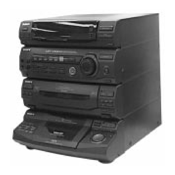
HCD-4800 is the tuner, deck, Video CD and
amplifier section in LBT-V4800/V4800R.
* Dolby noise reduction manufactured under
license from Dolby Laboratories
Licensing Corporation.
"DOLBY" and the double-D symbol a
are trademarks of Dolby Laboratories
Licensing Corporation.
MICROFILM
HCD-V4800
Model Name Using Similar Mechanism
CD
CD Mechanism Type
Section
Base Unit Name
Optical Pick-up Name
Tape deck
Model Name Using Similar Mechanism
Section
Tape Transport Mechanism Type
SPECIFICATIONS
MINI Hi-Fi COMPONENT SYSTEM
E Model
Chinese Model
HCD-V3500
CDM37L-5BD21AL
BU-5BD21AL
KSS-213D/Q-NP
HCD-V808
TCM-220WR2
– Continued on next page –
Advertisement
Table of Contents

Related Manuals for Sony HCD-V4800


Summary of Contents for Sony HCD-V4800
- Page 1 HCD-V4800 SERVICE MANUAL E Model Chinese Model HCD-4800 is the tuner, deck, Video CD and amplifier section in LBT-V4800/V4800R. * Dolby noise reduction manufactured under Model Name Using Similar Mechanism HCD-V3500 license from Dolby Laboratories CD Mechanism Type CDM37L-5BD21AL Licensing Corporation.
- Page 2 COMPONENTS IDENTIFIED BY MARK ! OR DOTTED LINE WITH MARK ! ON THE SCHEMATIC DIAGRAMS AND IN THE PARTS LIST ARE CRITICAL TO SAFE OPERATION. REPLACE THESE COMPONENTS WITH SONY PARTS WHOSE PART NUMBERS APPEAR AS SHOWN IN THIS MANUAL OR IN SUPPLEMENTS PUBLISHED BY SONY.
-
Page 3: Table Of Contents
TABLE OF CONTENTS SERVICING NOTES GENERAL ..............4 NOTES ON HANDLING THE OPTICAL PICK-UP BLOCK OR BASE UNIT DISASSEMBLY ............7 The laser diode in the optical pick-up block may suffer electro- static break-down because of the potential difference generated TEST MODE ............. -
Page 4: General
SECTION 1 GENERAL 1 POWER button LOCATION OF CONTROLS 2 SPECTRUM ANALYZER button — Front Panel — 3 DISPLAY/DEMO button 4 Remote control receiver 5 Fluorescent indicator tube 0 !¡ 6 EFFECT button and indicator 7 ENTER/NEXT button and indicator 8 TUNER MEMORY button 9 TUNING MODE button @£... - Page 5 $º $¡ $™ $£ $º SOUND CONTROL WAVE button $¡ SOUND CONTROL SURROUND button $™ P FILE MEMORY button $£ GEQ CONTROL button $¢ GROOVE button and indicator $∞ GEQ cursor control $§ ENTER button and indicator $¢ %¡ $¶ KEY CONTROL n button $•...
- Page 6 — Rear Panel — 1 FM ANTENNA terminal 2 AM ANTENNA terminal 3 VOLTAGE SELECTOR (except Malaysia, Thai models) 4 PHONO IN pin jack 5 VIDEO (AUDIO) IN pin jack 6 VIDEO (AUDIO) OUT pin jack 7 SPEAKER output terminal 8 VIDEO OUT pin jack 9 S VIDEO OUT connector 0 SYSTEM SELECT switch (NTSC/AUTO/PAL select)
-
Page 7: Disassembly
SECTION 2 DISASSEMBLY • This set can be disassembled in the order shown below. FRONT PANEL OPTICAL MAIN CD MECHANISM CASE BASE UNIT BD BOARD SECTION SECTION DECK SECTION PICK-UP (BU-5BD21AL) (Page 13) (Page 7) (Page 8) (KSS-213D/Q-NP) (Page 9) (CDM37L-5BD21AL) (Page 12) (Page 13) - Page 8 FRONT PANEL SECTION 1 flat wire (17 core) (CN102) 1 flat wire (11 core) (CN206) 1 flat wire (21 core) (CN205) 3 front panel section 2 four screws (BVTP 3 × 8) MAIN BOARD • Installing the power cord for the chinese model.
- Page 9 MAIN SECTION 1 flat wire (13 core) (CN202) 2 connector (CN203) 4 main section 3 two screws (BVTP 3 × 8) 3 eight screws (BVTP 3 × 8) 3 two screws (BVTP 3 × 8) CD MECHANISM DECK SECTION (CDM37L-5BD21AL) 2 five screws (BVTP 3 ×...
- Page 10 TAPE MECHANSM DECK SECTION (TCM-220WR2) 4 three screws 4 three screws (BVTP 2.6 × 8) (BVTP 2.6 × 8) 5 Remove the tape mechanism 3 flat wire (21 core) deck section (TCM-220WR2) (CN601) to derection of the arrow A . 3 flat wore (11 core) (CN1001) 2 Open the...
- Page 11 CD LID ASS’Y SECTION 6 four screws (BVTP 2.6 × 8) 5 connector (CN671) 7 CD lid ass’y 4 connector (CN661) 2 four screws (BVTP 2.6 × 8) 3 CD-B1 SW board 1 connector (CN642) PANEL (A) / (B) SUB ASS’Y 1 connector (CN612) 3 two claws...
- Page 12 BASE UNIT (BU-5BD21AL) 3 base unit (BU-5BD21AL) 1 yoke bracket 2 boss DISC TABLE Note: When the disc table is installed, adjust the positions of roller cam amd mark ( as shown in the figure, then set to the groove of disc table. 3 step screw 1 screw (BVTP 3 ×...
- Page 13 BD BOARD 1 two screws (PTPWH M2.6 × 6) 1 two screws (PTPWH M2.6 × 6) 2 optical pick-up section 3 two springs 3 two springs 4 flat wire (16 core) 5 screw (CN102) (BVTP 2.6 × 8) 7 BD board 6 Removal four solders.
- Page 14 CAPSTAN MOTOR (M1) 1 connector (CN651) 2 four screws (BTP 2.6 × 4) 3 Removal the AUDIO board to direction of the arrow A . 5 two scres (BTP 2.6 × 8) 7 Removal the capstan motor (M1) to direction of the arrow B . 4 Break the soldering of motor lead.
-
Page 15: Test Mode
SECTION 3 TEST MODE MC COLD RESET CHANGE-OVER OF AM TUNER STEP BETWEEN 9 kHz AND 10 kHz • The cold reset clears all data including preset data stored in the RAM to initial conditions. Execute this mode when returning the •... - Page 16 AGING MODE 7. In the aging mode, the aging is executed in a sequence given This mode can be used for operation check of CD section and tape in “2-2. Operation during Aging Mode”. deck section. The aging continues unless an alarm occurred. •...
- Page 17 VIDEO CD COLOR BAR MODE E-F BALANCE MODE On this mode, the data of the color bar signal as a picture signal Refer to the SECTION 6 ELECTRICAL ADJUSTMENTS page and the 1 kHz sine wave signal as a sound signal are output by the mechanism controller (IC701) for the video CD signal check.
-
Page 18: Mechanical Adjustments
SECTION 4 SECTION 5 MECHANICAL ADJUSTMENTS ELECTRICAL ADJUSTMENTS PRECAUTION DECK SECTION 0 dB=0.775 V 1. Clean the following parts with a denatured-alcohol-moistened 1. Demagnetize the record/playback head with a head demagne- swab: tizer. (Do not bring the head demagnetizer close to the erase record/playback head pinch roller head.) - Page 19 3. Mode: Playback (FWD) Tape Speed Adjustment DECK A Note: Start the Tape Speed adjustment as below after setting to the test test tape mode. P-4-A100 MAIN board oscilloscope In the test mode, the tape speed is high during pressing the (10 kHz, –10 dB) CN207 H SPEED DUB button.
- Page 20 Record bias Current Adjustment DECK B Adjustment and Connection Location: Procedure: 1. Mode: Record [AUDIO BOARD] (Conductor Side) RECORD TAPE SPEED pin 6 (L-CH) of IC1501 on the MAIN board. BAIS pin #¶ (R-CH) of IC1501 on the MAIN board. ...
-
Page 21: Cd Section
RF signal waveform CD SECTION VOLT/DIV: 200 mV TIME/DIV: 500 ns Notes: (with the 10: 1 probe 1. CD block basically constructed to operate without adjustment. There- in use) fore, check each item in order given. 2. Use YEDS-18 disc (Part No.: 3-702-101-01) unless otherwise indicated. +0.25 level: 1.3 Vp-p... -
Page 22: Video Section
RF PLL Free-run Frequency Check VIDEO SECTION Connection: Frequency Adjustment frequency counter Connection: BD board frequency counter TP (PLCK) VIDEO board – TP410 (DCLK) – Procedure: 1. Connect the frquency counter to TP (PLCK) on the BD board. Procedure: 2. Turned power switch on. 1. -
Page 23: Ic Pin Function Description
SECTION 6 DIAGRAMS 6-1. IC PIN FUNCTION DESCRIPTION MAIN BOARD IC301 µPD780016YGF-015-3BA (MASTER CONTROLLER) Pin No. Pin Name Function TA-MUTE Line mute control signal output terminal “L”: mute on DBFB-H/L DBFB normal/high selection signal output terminal “L”: DBFB high, “H”: DBFB low 427-LAT Serial data latch pulse output to the electrical volume (IC201) K-CON-LAT... - Page 24 Pin No. Pin Name Function COM-DOUT Serial data output to the electrical volume (IC201) and key control (IC501) COM-CLK Serial data transfer clock signal output to the electrical volume (IC201) and key control (IC501) CD-POWER Power on/off selection signal output for the CD circuit “H”: power on CD-DATA Serial data output terminal Not used (open) CD-CLK...
- Page 25 Pin No. Pin Name Function PB-A/B Deck-A/B selection signal output to the HA12203NT (IC1501) “L”: deck-A, “H”: deck-B Normal/high speed selection signal output to the HA12203NT (IC1501) EQ-H/N “L”: normal speed, “H”: high speed Recording bias on/off selection signal output to the HA12203NT (IC1501) BIAS “L”: bias off, “H”: bias on Recording mute on/off selection signal output to the HA12203NT (IC1501)
- Page 26 PANEL BOARD IC601 TMP87CH74-6566 (FLUORESCENT INDICATOR TUBE DRIVER, KEY CONTROL, LED DRIVER) Pin No. Pin Name Function LED3 LED drive signal output terminal (SUPER WOOFER, P (CD)) LED4 LED drive signal output terminal (· (CD)) LED5 LED drive signal output terminal (deck-B ª / ·) LED6 LED drive signal output terminal (P / r REC (TAPE)) LED7...
- Page 27 Pin No. Pin Name Function SIRCS Sircs input from the remote control receiver (IC602) VOL-B Rotary encoder pulse input from the S701 (VOLUME) JOG-B Jog dial pulse input from the S711 (≠ AMS ±) SPEANA-1 Spectrum analyzer drive signal input terminal (A/D input) SPEANA-2 VASS —...
- Page 28 VIDEO BOARD IC701 HD6433032SK12F (CD MECHANISM CONTROLLER) Pin No. Pin Name Function CMD0 CMD1 Two-way data bus with the IIC interface controller (IC901) CMD2 CMD3 SACK Data acknowledge output to the IIC interface controller (IC901) QINT Interrupt status input from the IIC interface controller (IC901) VDAC-XLAT Serial data latch pulse output to the video D/A converter (IC401) DF-XLAT...
- Page 29 Pin No. Pin Name Function STBY Hardware standby signal input terminal (fixed at “H”) RESET Reset signal input from the IIC interface controller (IC901) “L”: reset Non-maskable interrupt input terminal (fixed at “H”) — Ground terminal EXTAL System clock output terminal (10 MHz) XTAL System clock input terminal (10 MHz) —...
- Page 30 VIDEO BOARD IC901 µPD780016YGF-012-3BA (IIC INTERFACE CONTROLLER) Pin No. Pin Name Function 1 to 8 P80 to P87 Not used (fixed at “L”) TEST Test terminal (fixed at “L”) Main system clock output terminal (5 MHz) Main system clock input terminal (5 MHz) —...
- Page 31 Pin No. Pin Name Function NR-XCS Chip select signal output to the video noise reduction (IC301) Not used (fixed at “L”) Not used (fixed at “L”) — Ground terminal Not used (fixed at “L”) Not used (fixed at “L”) 74 to 81 P60 to P67 Not used (fixed at “L”) 82 to 85...
- Page 32 • Circuit Boards Location VIDEO POWER board TRANS board ENCAPSULATED COMPONENT (FM/AM TUNER UNIT) PANEL board KEY-CON board MAIN board HP/MIC board POWER AMP TC-A SW board board LED board CD-A SW board TC-B SW board CD-B1 SW board DOOR SW board CD-B2 SW board LEAF SWITCH board...
- Page 33 • IC Block Diagrams IC103 CXA1821M-T6 – BD Section – IC101 CXD2545Q 92 91 85 84 83 LD ON – – SUBCODE SUBCODE SBSO SRON SLED PWM SLED INTERFACE INTERFACE SRDR GENERATOR SERVO LC/PD PROCESSOR PROCESSOR APC LD AMP SFON VREF SERVO TFDR...
- Page 34 – VIDEO Section – IC101 CXD8567AM INIT D Vdd 2 SYSM L1 (+) A Vdd L SHIFT L2 (+) LATCH A Vss L 256FSO X Vss TEST1 512IN D Vss X OUT MCKSEL X Vdd XBCK A Vss R DATA R2 (+) LRCK A Vdd R...
- Page 35 IC271 BU6257FV-E2 16 15 14 13 12 CHARACTER HORIZONTAL WRITE SIZE ADDRESS ADDRESS REGISTER REGISTER COUNTER CHARACTER DATA HORIZONTAL HORIZONTAL HORIZONTAL 3 BIT × 288 WORD SIZE POSITION ADDRESS COUNTER COUNTER COUNTER COLOR DATA 3 BIT × 288 WORD VERTICAL CHARACTER DATA 8 BIT ×...
- Page 36 IC401 CXD1913Q 50 49 48 46 45 44 43 42 41 40 37-39 36 35 34 33 XTEST4 BURST FLAG CSYNC SYNC Slope SYNC Gen. Gen. XRST Sub Carrier Timing Controller TEST MODE Gen. SYSCLK PDCLK SIO and I O-Bus Closed Caption Encoder VSYNC (for NTSC)
-
Page 37: Deck Section
– DECK Section – IC602 µPC1330HA IC1502 LB1641 INVERTER T.S.D O.C.P MOTOR MOTOR DRIVE DRIVE COMPARATER SW P1 CONT GND SW R1 GND SW P2 GND SW R2 FWD/REV/STOP CONTROL LOGIC – MAIN/POWER SUPPLY Section – IC281 µPC1237HA IC901 LA5617 OVER LOAD DET CURRENT CURRENT... - Page 38 • Waveforms – BD Section – – VIDEO Section – 1 IC101 @§ (RFDC) 200 mV/DIV, 500 ns/DIV 6 IC101 $¶ (BCLK) 1 IC501 !§ (B3 (384FS)) +0.25 Vp-p 5.2 Vp-p –0.20 4.4 Vp-p 16.9344 MHz 474 ns 7 IC101 ^™ (XTAI) 2 IC501 9 (A8 (BCLK)) 2 IC101 @¶...
- Page 39 6 IC201 `⁄⁄¤ (BCKI) !¡ IC201 `⁄‚⁄ (LRCO) !§ IC271 8 (OSCIN) 3.7 Vp-p 5 Vp-p 4.3 Vp-p 6.75 MHz 22.7 µ s 474 ns 7 IC201 `⁄⁄‚ (LRCI) !™ IC201 (¢ (FID/FHREF), !¶ IC402 6 (SYSCLK) IC401 ^™ (FID) 5.1 Vp-p 4 Vp-p 5.1 Vp-p...
- Page 40 – MAIN Section – – PANEL Section – @¡ IC901 !º (X2) 1 IC301 !¡ (X1) 1 IC601 8 (X-OUT) 5.4 Vp-p 4.4 Vp-p 2.1 Vp-p 5 MHz 5 MHz 8 MHz @™ IC101 6 (384FSO) 2 IC301 !¢ (XT1) 3.1 Vp-p 3.1 Vp-p 16.9344 MHz...
-
Page 41: Exploded Views
SECTION 7 EXPLODED VIEWS NOTE: The components identified by mark • -XX and -X mean standardized parts, so they • Items marked “*” are not stocked since they ! or dotted line with mark ! are may have some difference from the original are seldom required for routine service. - Page 42 (2) FRONT PANEL SECTION-1 TCM-220WR2 not supplied not supplied supplied with S711 Ref. No. Part No. Description Remark Ref. No. Part No. Description Remark 4-987-995-01 SPRING (CD EJECT), COMPRESSION * 65 4-987-933-01 BRACKET (TA) 4-987-001-01 BUTTON (EJECT CD) 4-987-000-01 BUTTON (EJECT B) (6 EJECT) * 53 1-664-009-11 CD-A SW BOARD * 67...
- Page 43 (EFFECT. GROOVE. FUNCTION) 4-986-997-01 BUTTON (DECK. A) (ª. ·. p. 0. ). * 120 A-4403-138-A PANEL BOARD, COMPLETE DIRECTION. DOLBY NR) 4-963-404-21 EMBLEM (5-A), SONY 1-773-051-11 WIRE (FLAT TYPE) (17 CORE) 4-973-644-01 KNOB (MIC) X-4947-962-1 BUTTON (TUNER) ASSY 4-951-620-01 SCREW (2.6X8), +BVTP (TUNER/BAND.
- Page 44 (4) CHASSIS SECTION T901 not supplied IA, CH supplied MY, SP CDM37L-5BD21AL not supplied not supplied not supplied The components identified by mark ! or dotted line with mark ! are critical for safety. Replace only with part number not supplied specified.
- Page 45 (5) TAPE MECHANISM DECK SECTION-1 (TCM-220WR2) not supplied Ref. No. Part No. Description Remark Ref. No. Part No. Description Remark X-4946-820-1 HOLDER (BL) ASSY, CASSETTE * 207 4-980-439-01 FULCRUM, HOLDER X-4946-819-1 HOLDER (BR) ASSY, CASSETTE 3-354-957-01 JOINT (LOCK LEVER) 4-959-231-11 SPRING (L), TORSION * 209 3-354-953-01 LEVER (LOCK LEVER L) 4-959-232-11 SPRING (R), TORSION...
- Page 46 (6) TAPE MECHANISM DECK SECTION-2 (TCM-220WR2) (including r C) not supplied HP101 (including r A) not supplied not supplied HRPE101 (including r B) not supplied not supplied not supplied not supplied Ref. No. Part No. Description Remark Ref. No. Part No. Description Remark 3-908-560-01 SPRING, AZIMUTH ADJUSTMENT...
- Page 47 (7) TAPE MECHANISM DECK SECTION-3 (TCM-220WR2) r C : MOTOR board (supplied with AUDIO board) 307 306 not supplied Ref. No. Part No. Description Remark Ref. No. Part No. Description Remark 3-908-597-01 CAM (A) X-3370-171-1 FLYWHEEL (BR) ASSY 3-908-608-11 SCREW, STEP 3-908-600-01 LEVER (REV-B) X-3372-930-3 ARM (A) ASSY, FR * 316...
- Page 48 (8) CD MECHANISM DECK SECTION (CDM37L-5BD21AL) M201 BU-5BD21AL supplied Ref. No. Part No. Description Remark Ref. No. Part No. Description Remark 4-987-976-01 SCREW, STEP 4-978-426-01 INDICATOR (NO.) 4-944-490-01 BELT (TIMING) * 366 1-659-059-13 BD LED BOARD A-4660-978-A GEAR (PULLEY) ASSY * 367 1-659-058-13 TABLE SENSOR BOARD 4-978-421-01 GEAR (MID)
- Page 49 (9) BASE UNIT SECTION (BU-5BD21AL) M101 M102 The components identified by mark ! or dotted line with mark ! are critical for safety. Replace only with part number specified. Ref. No. Part No. Description Remark Ref. No. Part No. Description Remark ! 401 8-820-020-01 OPTICAL PICK-UP KSS-213D/Q-NP...
-
Page 50: Electrical Parts List
SECTION 8 AUDIO ELECTRICAL PARTS LIST NOTE: The components identified by mark • Items marked “*” are not stocked since they • Due to standardization, replacements in the ! or dotted line with mark ! are are seldom required for routine service. parts list may be different from the parts speci- critical for safety. - Page 51 AUDIO Ref. No. Part No. Description Remark Ref. No. Part No. Description Remark R601 1-249-409-11 CARBON 1/4W C156 1-163-237-11 CERAMIC CHIP 27PF R602 1-249-409-11 CARBON 1/4W C157 1-163-145-00 CERAMIC CHIP 0.0015uF 5% R608 1-249-409-11 CARBON 1/4W C159 1-163-019-00 CERAMIC CHIP 0.0068uF 10% 50V C161 1-163-038-00 CERAMIC CHIP...
- Page 52 BD LED CD MOTOR CD-A SW CD-B1 SW Ref. No. Part No. Description Remark Ref. No. Part No. Description Remark < SWITCH > R732 1-249-417-11 CARBON 1/4W R733 1-249-419-11 CARBON 1.5K 1/4W S101 1-572-085-11 SWITCH, LEAF (LIMIT) R734 1-249-421-11 CARBON 2.2K 1/4W ************************************************************...
- Page 53 CD-B2 SW DOOR SW HP/MIC Ref. No. Part No. Description Remark Ref. No. Part No. Description Remark C781 1-126-957-11 ELECT 0.22uF 20% 50V 1-664-011-11 CD-B2 SW BOARD C782 1-126-957-11 ELECT 0.22uF 20% 50V C783 1-126-967-11 ELECT 47uF 20% 10V *************** C784 1-136-495-11 FILM 0.068uF...
- Page 54 KEY-CON HP/MIC LEAF SWITCH Ref. No. Part No. Description Remark Ref. No. Part No. Description Remark R777 1-249-433-11 CARBON 1/4W < RESISTOR > R778 1-249-437-11 CARBON 1/4W R779 1-249-431-11 CARBON 1/4W R501 1-247-807-31 CARBON 1/4W R502 1-249-429-11 CARBON 1/4W < VARIABLE RESISTOR > R503 1-247-807-31 CARBON 1/4W...
- Page 55 MAIN Ref. No. Part No. Description Remark Ref. No. Part No. Description Remark C202 1-136-167-00 FILM 0.15uF 1-664-017-11 LED BOARD C203 1-130-493-00 MYLAR 0.068uF ********** C204 1-130-493-00 MYLAR 0.068uF < CONNECTOR > C205 1-130-486-00 MYLAR 0.018uF 10% 50V C206 1-130-486-00 MYLAR 0.018uF 10% 50V CN671...
- Page 56 MAIN Ref. No. Part No. Description Remark Ref. No. Part No. Description Remark C906 1-126-923-11 ELECT 220uF 20% 10V D306 8-719-987-63 DIODE 1N4148M C909 1-126-964-11 ELECT 10uF 20% 50V D307 8-719-987-63 DIODE 1N4148M C910 1-126-933-11 ELECT 100uF 20% 10V D309 8-719-987-63 DIODE 1N4148M C911 1-126-964-11 ELECT...
- Page 57 MAIN Ref. No. Part No. Description Remark Ref. No. Part No. Description Remark R159 1-260-091-11 CARBON 1/4W Q204 8-729-141-30 TRANSISTOR 2SC3623A-LK (SP, IA, CH) Q231 8-729-900-63 TRANSISTOR DTA124ES R171 1-249-424-11 CARBON 3.9K 1/4W R172 1-247-887-00 CARBON 220K 1/4W Q232 8-729-900-63 TRANSISTOR DTA124ES Q251 8-729-900-36 TRANSISTOR DTC124ES R176...
- Page 58 MAIN Ref. No. Part No. Description Remark Ref. No. Part No. Description Remark R288 1-249-438-11 CARBON 1/4W R916 1-249-409-11 CARBON 1/4W R289 1-249-437-11 CARBON 1/4W R917 1-249-409-11 CARBON 1/4W R291 1-249-433-11 CARBON 1/4W R918 1-249-425-11 CARBON 4.7K 1/4W R920 1-249-417-11 CARBON 1/4W R292 1-249-433-11 CARBON...
- Page 59 MOTOR PANEL Ref. No. Part No. Description Remark Ref. No. Part No. Description Remark D607 8-719-987-63 DIODE 1N4148M MOTOR BOARD D611 8-719-058-03 LED SEL5423E-TP15 (TUNER/BAND) ************* D612 8-719-058-03 LED SEL5423E-TP15 (TUNER/BAND) (Included in AUDIO BOARD, COMPLETE) D613 8-719-058-04 LED SEL5223S-TP15 (ENTER/NEXT) <...
- Page 60 PANEL Ref. No. Part No. Description Remark Ref. No. Part No. Description Remark R684 1-249-421-11 CARBON 2.2K 1/4W R610 1-247-843-11 CARBON 3.3K 1/4W R611 1-249-429-11 CARBON 1/4W R685 1-249-409-11 CARBON 1/4W R612 1-249-429-11 CARBON 1/4W R686 1-247-807-31 CARBON 1/4W R613 1-249-401-11 CARBON 1/4W R614...
- Page 61 POWER AMP TABLE SENSOR TC-A SW Ref. No. Part No. Description Remark Ref. No. Part No. Description Remark A-4398-968-A POWER AMP BOARD, COMPLETE (SP, IA, CH) A-4403-127-A POWER AMP BOARD, COMPLETE (MY) < RESISTOR > A-4403-592-A POWER AMP BOARD, COMPLETE (TH) R801 1-249-417-11 CARBON 1/4W...
- Page 62 TC-A SW TC-B SW TRANS VIDEO Ref. No. Part No. Description Remark Ref. No. Part No. Description Remark R706 1-249-407-11 CARBON 1/4W R707 1-249-409-11 CARBON 1/4W < CAPACITOR > R708 1-249-410-11 CARBON 1/4W C903 1-136-177-00 CERAMIC R709 1-249-412-11 CARBON 1/4W R710 1-249-414-11 CARBON 1/4W...
- Page 63 VIDEO Ref. No. Part No. Description Remark Ref. No. Part No. Description Remark C705 1-124-779-00 ELECT CHIP 10uF 20% 16V C203 1-163-038-00 CERAMIC CHIP 0.1uF C706 1-163-038-00 CERAMIC CHIP 0.1uF C204 1-163-038-00 CERAMIC CHIP 0.1uF C751 1-124-779-00 ELECT CHIP 10uF 20% 16V C205 1-163-038-00 CERAMIC CHIP...
- Page 64 VIDEO Ref. No. Part No. Description Remark Ref. No. Part No. Description Remark IC271 8-759-464-23 IC BU6257FV-E2 IC272 8-759-180-84 IC TC7W74F R206 1-216-295-00 CONDUCTOR, CHIP (2012) IC301 8-752-384-09 IC CXD1854Q R207 1-216-073-00 METAL CHIP 1/10W IC401 8-752-380-71 IC CXD1913Q R208 1-216-073-00 METAL CHIP 1/10W R209...
- Page 65 VIDEO VIDEO OUT Ref. No. Part No. Description Remark Ref. No. Part No. Description Remark R404 1-216-121-00 METAL CHIP 1/10W R725 1-216-073-00 METAL CHIP 1/10W R405 1-216-047-00 METAL CHIP 1/10W R726 1-216-073-00 METAL CHIP 1/10W R406 1-216-025-00 METAL CHIP 1/10W R727 1-216-073-00 METAL CHIP 1/10W...
- Page 66 VIDEO OUT VIDEO POWER Ref. No. Part No. Description Remark Ref. No. Part No. Description Remark 1-769-069-11 WIRE (FLAT TYPE) (16 CORE) < SWITCH > HP101 1-500-093-11 HEAD, MAGNETIC (PLAYBACK) (DECK A) HRPE1011-500-094-11 HEAD, MAGNETIC (REC/PB/ERASE) (DECK B) S9001 1-571-589-11 SWITCH, SLIDE (SYSTEM SELECT) X-3371-223-1 MOTOR ASSY (CAPSTAN) ************************************************************ A-2004-410-A MOTOR ASSY (TRIGGER)
- Page 67 HCD-V4800 Sony Corporation 97G057020-1 Printed in Singapore © 1997. 7 9-920-948-11 Home A&V Products Company Published by General Engineering Dept. – 114 – (Shibaura)
Need help?
Do you have a question about the HCD-V4800 and is the answer not in the manual?
Questions and answers