Table of Contents
Advertisement
Quick Links
Advertisement
Table of Contents

Related Manuals for DFI LanParty DK P35 Series


Summary of Contents for DFI LanParty DK P35 Series
- Page 1 System Board User’s Manual 935-DP35T1-004G 03110810A...
-
Page 2: Fcc And Doc Statement On Class B
Copyright This publication contains information that is protected by copyright. No part of it may be reproduced in any form or by any means or used to make any transformation/ adaptation without the prior written permission from the copyright holders. This publication is provided for informational purposes only. -
Page 3: Table Of Contents
Table of Contents About this Manual................Warranty....................Static Electricity Precaution..............Safety Measures..................About the Package................Before Using the System Board............System Board Layout................English.................................................................................. -
Page 4: About This Manual
(Main Board Utility CD) will appear. Click the “TOOLS” icon then click “Manual” on the main menu. For additional information on the system board, please download the complete version of the manual from DFI’s website. Visit www. dfi.com. Warranty 1. -
Page 5: Static Electricity Precaution
Introduction Static Electricity Precautions It is quite easy to inadver tently damage your PC, system board, components or devices even before installing them in your system unit. Static electrical discharge can damage computer components without causing any signs of physical damage. You must take extra care in handling them to ensure against electrostatic build-up. -
Page 6: About The Package
Introduction About the Package The system board package contains the following items. If any of these items are missing or damaged, please contact your dealer or sales representative for assistance. The system board A user’s manual One IDE cable One FDD cable Two Serial ATA data cables One Serial ATA power cable One RAID floppy diskette... -
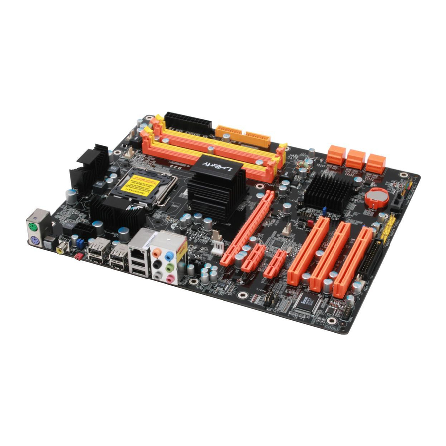
Page 7: System Board Layout
Introduction System Board Layout Mouse Optical power DIMM 2 DIMM 4 CPU fan S/PDIF-out DIMM 1 DIMM 3 PS/2 power select (JP7) power USB 6-11 power select (J 5) Clear CMOS (JP3) USB 8 USB 9 USB 6 JP15 USB 7 JP16 JP14 CPU FSB select... -
Page 8: English
English Chapter 1 - Specifications Processor • LGA 775 socket for: - Intel Core 2 Quad, Intel Core 2 Extreme, Intel Core ® ® ® Duo, Intel Pentium D or Intel Pentium ® ® ® ® • Supports Intel Enhanced Memory 64 Technology (EMT64T) •... - Page 9 English Rear Panel I/O • 1 mini-DIN-6 PS/2 mouse port • 1 mini-DIN-6 PS/2 keyboard port • 1 optical S/PDIF-out port • 1 coaxial RCA S/PDIF-out port • 6 USB 2.0/1.1 ports • 1 RJ45 LAN port • Center/subwoofer, rear R/L and side R/L jacks •...
-
Page 10: Jumper Settings
English Chapter 2 - Hardware Installation Jumper Settings Clear CMOS Data Clearing CMOS Data using Jumpers 1-2 On: Normal 2-3 On: (default) Clear CMOS Data PCI 1 PCI 2 1-2 On: Normal 2-3 On: (default) Clear CMOS Data PCI 3 If you encounter the following, a) CMOS data becomes corrupted. - Page 11 English To load the default values stored in the ROM BIOS, please follow the steps below. 1. Power-off the system then unplug the power cord. 2. Set JP2 or JP3 pins 2 and 3 to On. Wait for a few seconds and set JP2 or JP3 back to its default setting, pins 1 and 2 On.
-
Page 12: Usb Power Select
English PS/2 Power Select 1-2 On: 5V 2-3 On: (default) 5VSB Important: The 5VSB power source of your power supply must support ≥720mA. PCI 1 PCI 2 PCI 3 Selecting 5VSB will allow you to use the PS/2 keyboard or PS/2 mouse to wake up the system. - Page 13 English CPU FSB Select JP14 JP16 JP15 PCI 1 PCI 2 PCI 3 By default, the three jumpers are all set to pins 1 and 2 On. This setting will allow the system to automatically run according to the CPU’s FSB. If you want to change the setting, please refer to the table below.
-
Page 14: Secondary Rtc Reset
English Secondary RTC Reset JP12 PCI 1 1-2 On: Normal 2-3 On: PCI 2 (default) RTC reset PCI 3 When the RTC batter y is removed, this jumper resets the manageability register bits in the RTC. Note: 1. The SRTCRST# input must always be high when all other RTC power planes are on. - Page 15 English PS/2 Ports and S/PDIF Ports PS/2 Mouse PS/2 KB Optical S/PDIF Coaxial RCA S/PDIF PCI 1 PCI 2 PCI 3 PS/2 Mouse and PS/2 Keyboard Ports These por ts are used to connect a PS/2 mouse and a PS/2 keyboard.
- Page 16 English USB Ports and LAN Port USB 9 USB 8 USB 7 USB 6 USB 11 USB 10 PCI 1 PCI 2 PCI 3 USB 4-5 USB 0-1 USB 2-3 USB Ports The USB por ts are used to connect USB 2.0/1.1 devices. The 10- pin connectors allow you to connect 6 additional USB 2.0/1.1 ports.
- Page 17 English Audio Rear audio Center/ Line-in Subwoofer Front R/L Rear R/L Mic-in Side R/L Front audio PCI 1 PCI 2 PCI 3 Right audio channel Ground CD-in Ground Left audio channel Rear Panel Audio Center/Subwoofer Jack (Orange) This jack is used to connect to the center and subwoofer speakers of the audio system.
-
Page 18: Serial Ata Connectors
English Mic-in Jack (Pink) This jack is used to connect an external microphone. Front Audio The front audio connector is used to connect to the line-out and mic-in jacks that are at the front panel of your system. CD-in The CD-in connector is used to receive audio from a CD-ROM drive, TV tuner or MPEG card. - Page 19 English Floppy Disk Drive Connector and IDE Connector PCI 1 PCI 2 PCI 3 Floppy Disk Drive Connector The floppy disk drive connector is used to connect a floppy drive. Inser t one end of the floppy cable into this connector and the other end-most connector to the floppy drive.
- Page 20 English IrDA and Serial (COM) Connectors IRRX N. C. Ground IRTX IrDA PCI 1 PCI 2 COM 1 PCI 3 IrDA Connector This connector is used to connect an IrDA module. Note: The sequence of the pin functions on some IrDA cable may be reversed from the pin function defined on the system board.
-
Page 21: Cooling Fan Connectors
English Cooling Fan Connectors Sense Power Speed Control Ground CPU fan On/Off Power Sense Fan 2 PCI 1 PCI 2 N. C. Ground PCI 3 Power Fan 3 These fan connectors are used to connect cooling fans. Cooling fans will provide adequate airflow throughout the chassis to pre- vent overheating the CPU and system board components. -
Page 22: Power Connectors
English Power Connectors Use a power supply that complies with the ATX12V Power Supply Design Guide Version 1.1. An ATX12V power supply unit has a standard 24-pin ATX main power connector that must be inserted into this connector. 12 24 +3.3VDC +12VDC +5VDC... - Page 23 English The power connectors from the power supply unit are designed to fit the 24-pin and 8-pin connectors in only one orientation. Make sure to find the proper orientation before plugging the connectors. The FDD-type power connector is an additional power connector. If you are using more than one graphics cards, we recommend that you plug a power cable from your power supply unit to the 5V/12V power connector.
- Page 24 English Restarting the PC Normally, you can power-off the PC by: 1. Pressing the power button at the front panel of the chassis. 2. Pressing the power switch that is on the system board (note: not all system boards come with this switch). If for some reasons you need to totally cut off the power supplied to the PC, switch off the power supply or unplug the power cord.
- Page 25 English Front Panel Connectors and LEDs DRAM Power LED RESET PCI 1 SPEAKER HD-LED PCI 2 PCI 3 Standby PWR-LED Power LED ATX-SW HD-LED: Primary/Secondary IDE LED This LED will light when the hard drive is being accessed. RESET: Reset Switch This switch allows you to reboot without having to power off the system thus prolonging the life of the power supply or system.
- Page 26 English PWR-LED: Power/Standby LED When the system’s power is on, this LED will light. When the system is in the S1 (POS - Power On Suspend) or S3 (STR - Suspend To RAM) state, it will blink every second. Note: If a system did not boot-up and the Power/Standby LED did not light after it was powered-on, it may indicate that the CPU or memory module was not installed properly.
-
Page 27: Pci Express Slots
English PCI Express Slots PCI Express x16 PCI Express x1 PCI Express x1 PCI 1 PCI 2 PCI 3 PCI Express x16 Install PCI Express x16 graphics card, that comply to the PCI Ex- press specifications, into the PCI Express x16 slot. To install a graphics card into the x16 slot, align the graphics card above the slot then press it down firmly until it is completely seated in the slot. -
Page 28: Raid Levels
English Chapter 3 - RAID The Intel ICH9R chip alows configuring RAID on Serial ATA drives. It supports RAID 0, RAID 1, RAID 0+1 and RAID 5. RAID Levels RAID 0 (Striped Disk Array without Fault Tolerance) RAID 0 uses two new identical hard disk drives to read and write data in parallel, interleaved stacks. - Page 29 English Step 1: Connect the Serial ATA Drives Refer to chapter 2 for details on connecting the Serial ATA drives. Important: Make sure you have installed the Serial ATA drives and connected the data cables otherwise you won’t be able to enter the RAID BIOS utility. Treat the cables with extreme caution especially while creating RAID.
- Page 30 English Step 4: Install the RAID Driver During OS Installation ® The RAID driver must be installed during the Windows XP or ® Windows 2000 installation using the F6 installation method. This is required in order to install the operating system onto a hard drive or RAID volume when in RAID mode or onto a hard drive when in AHCI mode.
- Page 34 PCI 1 PCI 2 PCI 3...
- Page 36 1-2 On: 5V 2-3 On: 5VSB PCI 1 PCI 2 PCI 3 USB 6-11 (JP5) 2-3 On: 5VSB PCI 1 USB 0-5 (JP6) PCI 2 2-3 On: PCI 3 5VSB...
- Page 37 JP14 JP16 JP15 PCI 1 PCI 2 PCI 3...
- Page 38 JP12 PCI 1 PCI 2 PCI 3 Rear R/L Line-in Front R/L Mic-in USB 8-9 USB 6-7 Side R/L USB 10-11 Clear CMOS S/PDIF-out...
- Page 39 S/PDIF PCI 1 PCI 2 PCI 3...
- Page 40 PCI 1 PCI 2 PCI 3...
- Page 41 PCI 1 PCI 2 PCI 3...
- Page 43 SATA 0-1 SATA 2-3 PCI 1 SATA 4-5 PCI 2 PCI 3...
- Page 44 PCI 1 PCI 2 PCI 3...
- Page 45 IRRX N. C. Ground IRTX IrDA PCI 1 PCI 2 COM 1 PCI 3...
- Page 46 Sense Power Speed Control Ground CPU fan On/Off Power Sense Fan 2 PCI 1 PCI 2 N. C. Ground PCI 3 Power Fan 3 Reset Power PCI 1 PCI 2 PCI 3...
- Page 47 12 24 +3.3VDC +12VDC +5VDC +12VDC +5VDC +5VSB +5VDC PWR_OK +5VDC PS_ON# +5VDC -12VDC +3.3VDC PCI 1 +3.3VDC +3.3VDC PCI 2 PCI 3 Ground +12V PCI 1 PCI 2 PCI 3...
- Page 48 Ground Ground +12V PCI 1 PCI 2 PCI 3...
- Page 50 DRAM Power LED RESET PCI 1 SPEAKER HD-LED PCI 2 PCI 3 PWR-LED Standby Power LED ATX-SW...
- Page 52 PCI Express x16 PCI Express x1 PCI Express x1 PCI 1 PCI 2 PCI 3...
- Page 55 ® ®...
- Page 56 ®...
- Page 59 PCI 1 PCI 2 PCI 3...
- Page 61 2-3 On: 5VSB PCI 1 PCI 2 PCI 3 USB 6-11 (JP5) 2-3 On: 5VSB PCI 1 USB 0-5 (JP6) PCI 2 2-3 On: PCI 3 5VSB...
- Page 62 • • JP14 JP16 JP15 PCI 1 PCI 2 PCI 3...
- Page 63 JP12 PCI 1 PCI 2 PCI 3 Rear R/L Line-in Front R/L Mic-in USB 8-9 USB 6-7 Side R/L USB 10-11...
- Page 64 PCI 1 PCI 2 PCI 3...
- Page 65 USB 9 USB 8 USB 7 USB 6 USB 11 USB 10 PCI 1 PCI 2 PCI 3 USB 4-5 USB 0-1 USB 2-3...
- Page 66 Line-in Front R/L Rear R/L Mic-in Side R/L PCI 1 PCI 2 PCI 3 Right audio channel Ground CD-in Ground Left audio channel...
- Page 68 SATA 0-1 SATA 2-3 PCI 1 SATA 4-5 PCI 2 PCI 3...
- Page 69 PCI 1 PCI 2 PCI 3...
- Page 70 IRRX N. C. Ground IRTX IrDA PCI 1 PCI 2 COM 1 PCI 3...
- Page 71 Sense Power Speed Ground Control CPU fan On/Off Power Sense Fan 2 PCI 1 PCI 2 N. C. Ground PCI 3 Power Fan 3 Reset Power PCI 1 PCI 2 PCI 3...
- Page 72 12 24 +3.3VDC +12VDC +5VDC +12VDC +5VDC +5VDC +5VSB PWR_OK +5VDC PS_ON# +5VDC -12VDC +3.3VDC PCI 1 +3.3VDC +3.3VDC PCI 2 PCI 3 Ground +12V PCI 1 PCI 2 PCI 3...
- Page 73 Ground Ground +12V PCI 1 PCI 2 PCI 3...
- Page 75 DRAM Power LED RESET PCI 1 SPEAKER HD-LED PCI 2 PCI 3 PWR-LED Standby ATX-SW Power LED...
- Page 77 PCI Express x16 PCI Express x1 PCI Express x1 PCI 1 PCI 2 PCI 3...
- Page 79 ® ®...
- Page 81 ® ® ® ® ® ® ® ® ® ® ®...
- Page 83 PCI 1 PCI 2 PCI 3...
- Page 85 1-2 On: 5V 2-3 On: 5VSB PCI 1 PCI 2 PCI 3...
- Page 86 USB 6-11 (JP5) 2-3 On: 1-2 On: 5V 5VSB PCI 1 USB 0-5 (JP6) PCI 2 1-2 On: 5V 2-3 On: PCI 3 5VSB...
- Page 87 JP14 JP16 JP15 PCI 1 PCI 2 PCI 3 FSB 1333 FSB 800 FSB 1066 JP14 1-2 On 2-3 On 2-3 On 2-3 On JP15 1-2 On 2-3 On 3-4 On 2-3 On JP16 1-2 On 2-3 On 2-3 On 3-4 On...
- Page 88 JP12 PCI 1 PCI 2 PCI 3 Center/Subwoofer Rear R/L PS/2 Line-in Front R/L Mic-in USB 8-9 USB 6-7 Side R/L USB 10-11 S/PDIF-out...
- Page 89 PS/2 PS/2 S/PDIF PCI 1 PCI 2 PCI 3...
- Page 90 USB 9 USB 8 USB 7 USB 6 USB 11 USB 10 PCI 1 PCI 2 PCI 3 USB 4-5 USB 0-1 USB 2-3...
- Page 91 Rear audio Center/ Line-in Subwoofer Front R/L Rear R/L Mic-in Side R/L Front audio PCI 1 PCI 2 PCI 3 Right audio channel Ground CD-in Ground Left audio channel...
- Page 93 SATA 0-1 SATA 2-3 PCI 1 SATA 4-5 PCI 2 PCI 3...
- Page 94 PCI 1 PCI 2 PCI 3...
- Page 95 IRRX N. C. Ground IRTX IrDA PCI 1 PCI 2 COM 1 PCI 3...
- Page 96 Sense Power Speed Ground Control CPU fan On/Off Power Sense Fan 2 PCI 1 PCI 2 N. C. Ground PCI 3 Power Fan 3...
- Page 97 Reset Power PCI 1 PCI 2 PCI 3...
- Page 98 12 24 +3.3VDC +12VDC +5VDC +12VDC +5VDC +5VDC +5VSB PWR_OK +5VDC PS_ON# +5VDC -12VDC +3.3VDC PCI 1 +3.3VDC +3.3VDC PCI 2 PCI 3 +12V Ground PCI 1 PCI 2 PCI 3...
- Page 99 Ground Ground +12V PCI 1 PCI 2 PCI 3...
- Page 101 RESET PCI 1 SPEAKER HD-LED PCI 2 PCI 3 PWR-LED ATX-SW...
- Page 102 HDD LED Power HD-LED N. C. N. C. PWRBT+ ATX-SW PWRBT- N. C. N. C. RESET Ground H/W Reset Speaker Data N. C. SPEAKER Ground Speaker Power LED Power (+) LED Power (+) PWR-LED LED Power (-) or Standby Signal...
- Page 103 PCI Express x16 PCI Express x1 PCI Express x1 PCI 1 PCI 2 PCI 3...
Need help?
Do you have a question about the LanParty DK P35 Series and is the answer not in the manual?
Questions and answers