Table of Contents
Advertisement
Advertisement
Table of Contents

Related Manuals for DFI 790fx-m2r


Summary of Contents for DFI 790fx-m2r
-
Page 1: System Board
System Board User’s Manual 935-D790M1-104G 02710751A... -
Page 2: Fcc And Doc Statement On Class B
Copyright This publication contains information that is protected by copyright. No par t of it may be reproduced in any form or by any means or used to make any transfor- mation/adaptation without the prior written permission from the copyright holders. -
Page 3: Table Of Contents
Table of Contents About this Manual................Warranty....................Static Electricity Precaution..............Safety Measures..................About the Package................Before Using the System Board............System Board Layout................English................................................................................. -
Page 4: About This Manual
(Main Board Utility CD) will appear. Click the “TOOLS” icon then click “Manual” on the main menu. For additional information on the system board, please download the complete version of the manual from DFI’s website. Visit www. dfi.com. Warranty 1. -
Page 5: Static Electricity Precaution
Introduction Static Electricity Precautions It is quite easy to inadver tently damage your PC, system board, components or devices even before installing them in your system unit. Static electrical discharge can damage computer components without causing any signs of physical damage. You must take extra care in handling them to ensure against electrostatic build-up. -
Page 6: About The Package
Introduction About the Package The system board package contains the following items. If any of these items are missing or damaged, please contact your dealer or sales representative for assistance. One system board One Bernstein audio module with cable One Transpiper kit - One Transpiper - One metal pipe... -
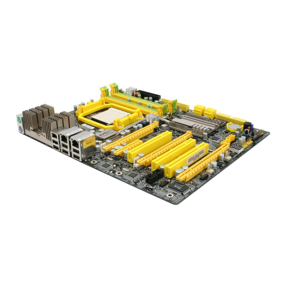
Page 7: System Board Layout
Introduction System Board Layout... -
Page 8: English
English Chapter 1 - Specifications Processor ® • AMD Phenom / Athlon 64 X2 / Athlon 64 FX / Athlon • Socket 940 AM2 65nm • HyperTranspor t 3.0 and 1.0 Chipset • AMD chipset - Nor thbridge: AMD 790FX - Southbridge: AMD SB600 System Memory •... - Page 9 English IEEE 1394 • VIA VT6307 • Suppor ts two 100/200/400 Mb/sec por ts Serial ATA with • AMD SB600 RAID - Suppor ts up to 4 SATA devices - SATA speed up to 3Gb/s - RAID 0, RAID 1 and RAID 0+1 •...
-
Page 10: Jumper Settings
English Chapter 2 - Hardware Installation Jumper Settings Clear CMOS Data Clearing CMOS Data using JP2 1-2 On: Normal 2-3 On: (default) Clear CMOS Data If you encounter the following, a) CMOS data becomes corrupted. b) You forgot the supervisor or user password. c) The overclocked settings in the BIOS resulted to the system’s in- stability or caused system boot up problems. - Page 11 English ® Clearing CMOS Data using the EZ Clear Function ® EZ Clear bypasses the manual process of using a jumper to clear the CMOS by simply using the reset and power buttons. Important: ® EZ Clear is supported only if standby power is present in the system.
-
Page 12: Usb Power Select
English PS/2 Power Select 1-2 On: 5V 2-3 On: (default) 5VSB Important: The 5VSB power source of your p o w e r s u p p l y m u s t s u p p o r t ≥720mA. - Page 13 English Speaker On/Off Select Buzzer 1-2 On: 2-3 On: Speaker Off Speaker On (default) The system board is equipped with a buzzer which serves as the PC’s speaker. By default the buzzer is “on” allowing you to hear the system’s beep messages and warnings. If you intend to use an exter- nal speaker, turn this function off by setting JP8 pins 1 and 2 to On.
- Page 14 English Rear Panel I/O Ports PS/2 LAN 1 LAN 2 Mouse 1394-0 USB 0-1 USB 4-5 PS/2 USB 2-3 PS/2 Ports and IEEE 1394 Ports PS/2 Mouse PS/2 KB 1394-0 1394-1 PS/2 Mouse and PS/2 Keyboard Ports These por ts are used to connect a PS/2 mouse and a PS/2 keyboard.
- Page 15 English USB Ports and LAN Ports USB 1 USB 0 LAN 1 USB 3 USB 2 LAN 2 USB 5 USB 4 USB 6-7 USB 8-9 USB Ports The USB ports are used to connect USB 2.0/1.1 devices. The 10-pin connectors allow you to connect 4 additional USB 2.0/1.1 por ts.
-
Page 16: Bernstein Audio Module
English Bernstein Audio Module Audio Module Options CD-in CD-in Line-in Front Line-out Front audio audio Mic-in Optical Optical S/PDIF Center/ S/PDIF Subwoofer VoIP card Rear R/L connector Side R/L S/PDIF-out S/PDIF-in Bernstein Bernstein audio module audio module connector connector Side view Bernstein audio module Bernstein audio module using Realtek ALC885... - Page 17 English CD-in Connector The CD-in connector is used to receive audio from a CD-ROM drive, TV tuner or MPEG card. Front Audio Connector The front audio connector is used to connect to the line-out and mic-in jacks that are at the front panel of your system. Optical S/PDIF Connector The optical S/PDIF connector is used to connect an external audio output device using an optical S/PDIF cable.
- Page 18 English 3. The length of the audio cable provides the option and flexibil- ity of installing the module on any available expansion bracket slot at the rear of the system chassis. Remove the screw of the bracket where you want the audio module installed then re- move the bracket.
- Page 19 English 3. Connect one end of the VoIP cable to the Bernstein audio module and the other end to the connector on the VoIP card. Connector on VoIP card Connector on ALC888T Bernstein audio module VoIP cable Side view VoIP card and cable properly connected Left audio channel Ground Ground...
-
Page 20: Serial Ata Connectors
English I/O Connectors Serial ATA Connectors SATA 1-2 SATA 1-4 suppor ted by AMD SB600 SATA 3-4 SATA 6 SATA 5-6 suppor ted by Silicon Image SiI3132 SATA 5 The Serial ATA (SATA) connectors are used to connect Serial ATA drives. - Page 21 English Floppy Disk Drive Connector and IDE Connector Floppy Disk Drive Connector The 90 floppy disk drive connector is used to connect a floppy drive. It has a keying mechanism to prevent improper floppy cable installation. Insert one end of the floppy cable into this connector and the other end-most connector to the floppy drive.
- Page 22 English IrDA, CIR and Serial (COM) Connectors IRRX Ground N. C. IRTX IrDA CIRTX 5VSB N. C. Ground CIRRX IrDA and CIR Connectors These connectors are used to connect an IrDA module and/or CIR module. Note: The sequence of the pin functions on some IrDA/CIR cable may be reversed from the pin function defined on the system board.
-
Page 23: Cooling Fan Connectors
English Cooling Fan Connectors Sense Power Power Speed Ground N. C. Ground Control Fan 2 CPU fan On/Off Power Sense N. C. Ground Power 3rd fan NB fan N. C. Ground N. C. Ground Power Power 1st fan 2nd fan These fan connectors are used to connect cooling fans. - Page 24 English LEDs DRAM Power LED Standby Diagnostic Power LED DRAM Power LED This LED will light when the system’s power is on. Standby Power LED This LED will light when the system is in the standby mode. Diagnostic LED The Diagnostic LED displays POST codes. POST (Power-On Self Tests) which is controlled by the BIOS is performed whenever you power-on the system.
-
Page 25: Power Connectors
English Power Connectors Use a power supply that complies with the ATX12V Power Supply Design Guide Version 1.1. An ATX12V power supply unit has a standard 24-pin ATX main power connector that must be inserted into this connector. 1 2 2 4 +3.3VDC +12VDC +5VDC... - Page 26 English The power connectors from the power supply unit are designed to fit the 24-pin and 8-pin connectors in only one orientation. Make sure to find the proper orientation before plugging the connectors. The FDD-type power connectors are additional power connector.s If you are using more than one graphics cards, we recommend that you plug power cables from your power supply unit onto the 5V/ 12V power connectors.
- Page 27 English Restarting the PC Normally, you can power-off the PC by: 1. Pressing the power button at the front panel of the chassis. 2. Pressing the power switch that is on the system board (note: not all system boards come with this switch). If for some reasons you need to totally cut off the power supplied to the PC, switch off the power supply or unplug the power cord.
-
Page 28: Front Panel Connectors
English Front Panel Connectors RESET SPEAKER HD-LED PWR-LED ATX-SW HD-LED: Primary/Secondary IDE LED This LED will light when the hard drive is being accessed. RESET: Reset Switch This switch allows you to reboot without having to power off the system thus prolonging the life of the power supply or system. SPEAKER: Speaker Connector This connects to the speaker installed in the system chassis. - Page 29 English PWR-LED: Power/Standby LED When the system’s power is on, this LED will light. When the system is in the S1 (POS - Power On Suspend) or S3 (STR - Suspend To RAM) state, it will blink every second. Note: If a system did not boot-up and the Power/Standby LED did not light after it was powered-on, it may indicate that the CPU or memor y module was not installed properly.
-
Page 30: Pci Express Slots
English PCI Express Slots PCI Express x16 PCI Express x4 PCI Express x16 PCI Express x16 PCI Express x16 Install PCI Express x16 graphics card, that comply to the PCI Ex- press specifications, into the PCI Express x16 slot. To install a graph- ics card into the x16 slot, align the graphics card above the slot then press it down firmly until it is completely seated in the slot. -
Page 31: Raid Levels
English Chapter 3 - RAID The AMD SB600 chip alows configuring RAID on 4 Serial ATA drives. It suppor ts RAID 0, RAID 1 and RAID 0+1. The Silicon Image Sil3132 chip allows configuring RAID on another 2 Serial ATA drives. - Page 32 English Step 1: Connect the Serial ATA Drives Refer to chapter 2 for details on connecting the Serial ATA drives. Important: 1. Make sure you have installed the Serial ATA drives and connected the data cables otherwise you won’t be able to enter the RAID BIOS utility. 2.
- Page 33 English Step 4: Install the RAID Driver During OS Installation ® The RAID driver must be installed during the Windows XP or ® Windows 2000 installation using the F6 installation method. This is required in order to install the operating system onto a hard drive or RAID volume when in RAID mode or onto a hard drive when in AHCI mode.
- Page 34 ®...
- Page 35 • •...
- Page 38 Reset Power...
- Page 39 2-3 On: 5VSB 1-2 On: 5V USB 0-5 (JP5) USB 6-9 (JP6)
- Page 41 LAN 1 LAN 2 1394-0 USB 0-1 USB 4-5 USB 2-3 1394_0 1394-1...
- Page 42 USB 1 USB 0 LAN 1 USB 3 USB 2 LAN 2 USB 5 USB 4 USB 6-7 USB 8-9...
- Page 43 Line-in Line-out Mic-in Rear R/L Side R/L S/PDIF-out S/PDIF-in...
- Page 47 Left audio channel Ground Ground Right audio channel CD-in 10 9 Line out Jet Detect Line out_Left Sense N. C. Line out_Right Mic Jet Detect Mic_Right Mic_Left SPDIF in SPDIF out...
- Page 48 SATA 1-2 SATA 3-4 SATA 6 SATA 5...
- Page 50 IRRX Ground N. C. IRTX IrDA CIRTX 5VSB Ground N. C. CIRRX...
- Page 51 Sense Power Power Ground Speed N. C. Control Ground Fan 2 CPU fan On/Off Power Sense N. C. Ground Power 3rd fan NB fan N. C. Ground N. C. Ground Power Power 1st fan 2nd fan Reset Power...
- Page 52 DRAM Power LED Standby Diagnostic Power LED...
- Page 53 12 24 +3.3VDC +12VDC +5VDC +12VDC +5VDC +5VDC +5VSB PWR_OK +5VDC PS_ON# +5VDC -12VDC +3.3VDC +3.3VDC +3.3VDC +12V Ground...
- Page 54 +12V Ground Ground...
- Page 56 RESET SPEAKER HD-LED PWR-LED ATX-SW...
- Page 58 PCI Express x16 PCI Express x4 PCI Express x16 PCI Express x16 PCIE 3 PCIE 1 PCIE 2 PCIE 4 x2 or x4 N.C. x2 or x4 N.C. CrossFire CrossFire +...
- Page 60 SATA 1-2 SATA 3-4 SATA 6 SATA 5...
- Page 61 ® ®...
- Page 63 ®...
- Page 67 Reset Power...
- Page 68 2-3 On: 5VSB USB 0-5 (JP5) USB 6-9 (JP6)
-
Page 70: Lan 1 Lan
LAN 1 LAN 2 1394-0 USB 0-1 USB 4-5 USB 2-3 1394_0 1394-1... - Page 71 USB 1 USB 0 LAN 1 USB 3 USB 2 LAN 2 USB 5 USB 4 USB 6-7 USB 8-9...
- Page 72 Line-in Line-out Mic-in Rear R/L Side R/L S/PDIF-out S/PDIF-in Realtek ALC888T...
- Page 75 Realtek ALC888T Realtek ALC888T...
- Page 76 Left audio channel Ground Ground Right audio channel CD-in 10 9 Line out Jet Detect Line out_Left Sense N. C. Line out_Right Mic Jet Detect Mic_Right Mic_Left SPDIF in SPDIF out...
- Page 77 SATA 1-2 SATA 3-4 SATA 6 SATA 5...
- Page 79 IRRX Ground N. C. IRTX IrDA CIRTX 5VSB Ground N. C. CIRRX...
- Page 80 Sense Power Power Speed Ground N. C. Ground Control Fan 2 CPU fan On/Off Power Sense N. C. Ground Power 3rd fan NB fan N. C. Ground N. C. Ground Power Power 1st fan 2nd fan Reset Power...
- Page 81 DRAM Power LED Standby Diagnostic Power LED...
- Page 82 12 24 +3.3VDC +12VDC +5VDC +12VDC +5VDC +5VSB +5VDC PWR_OK +5VDC PS_ON# +5VDC -12VDC +3.3VDC +3.3VDC +3.3VDC +12V Ground...
- Page 83 +12V Ground Ground...
- Page 85 RESET SPEAKER HD-LED PWR-LED ATX-SW...
- Page 87 PCI Express x16 PCI Express x4 PCI Express x16 PCI Express x16 PCIE 3 PCIE 1 PCIE 2 PCIE 4 x2 or x4 N.C. x2 or x4 N.C. 3-way CrossFire 2-way CrossFire + Physics...
- Page 89 SATA 1-2 SATA 3-4 SATA 6 SATA 5...
- Page 90 ® ®...
- Page 92 ® ®...
- Page 93 • • • • •...
- Page 95 Reset Power...
- Page 96 1-2 On: 5V 2-3 On: 5VSB...
- Page 97 USB 0-5 (JP5) 1-2 On: 5V 2-3 On: 5VSB USB 6-9 (JP6) 1-2 On: 5V 2-3 On: 5VSB...
- Page 99 PS/2 LAN 1 LAN 2 1394-0 PS/2 USB 0-1 USB 4-5 USB 2-3 PS/2 Mouse PS/2 KB 1394-0 1394-1...
- Page 100 USB 1 USB 0 LAN 1 USB 3 USB 2 LAN 2 USB 5 USB 4 USB 6-7 USB 8-9...
- Page 101 CD-in CD-in Line-in Front Line-out Front audio audio Mic-in Optical Optical S/PDIF Center/ S/PDIF Subwoofer VoIP card Rear R/L connector Side R/L S/PDIF-out S/PDIF-in Side view...
- Page 102 Left audio channel Ground Ground Right audio channel CD-in 10 9 Line out Jet Detect Line out_Left Sense N. C. Line out_Right Mic Jet Detect Mic_Right Mic_Left Front audio SPDIF in SPDIF out Optical S/PDIF...
- Page 106 SATA 1-2 SATA 3-4 SATA 6 SATA 5...
- Page 108 IRRX Ground N. C. IRTX IrDA CIRTX 5VSB N. C. Ground CIRRX...
- Page 109 Sense Power Power Speed Ground N. C. Control Ground Fan 2 CPU fan On/Off Power Sense N. C. Ground Power 3rd fan NB fan N. C. Ground N. C. Ground Power Power 1st fan 2nd fan...
- Page 110 Reset Power...
- Page 112 12 24 +3.3VDC +12VDC +5VDC +12VDC +5VDC +5VDC +5VSB PWR_OK +5VDC PS_ON# +5VDC -12VDC +3.3VDC +3.3VDC +3.3VDC +12V Ground...
- Page 113 +12V Ground Ground...
- Page 115 RESET SPEAKER HD-LED PWR-LED ATX-SW...
- Page 116 HDD LED Power HD-LED N. C. N. C. PWRBT+ ATX-SW PWRBT- N. C. N. C. RESET Ground H/W Reset Speaker Data N. C. SPEAKER Ground Speaker Power LED Power (+) LED Power (+) PWR-LED LED Power (-) or Standby Signal...
- Page 117 PCI Express x16 PCI Express x4 PCI Express x16 PCI Express x16 PCIE 1 PCIE 2 PCIE 3 PCIE 4 x2 or x4 N.C. x2 or x4 N.C.
- Page 119 SATA 1-2 SATA 3-4 SATA 6 SATA 5...
Need help?
Do you have a question about the 790fx-m2r and is the answer not in the manual?
Questions and answers