Table of Contents
Advertisement
Quick Links
Quick Installation Guide
Moxa Americas:
Toll-free: 1-888-669-2872
Tel:
1-714-528-6777
Fax:
1-714-528-6778
Moxa Europe:
Tel:
+49-89-3 70 03 99-0
Fax:
+49-89-3 70 03 99-99
Moxa India:
Tel:
+91-80-4172-9088
Fax:
+91-80-4132-1045
TCF-142-RM Series
Version 6.0, February 2020
Technical Support Contact Information
www.moxa.com/support
2020 Moxa Inc. All rights reserved.
Moxa China (Shanghai office):
Toll-free: 800-820-5036
Tel:
+86-21-5258-9955
Fax:
+86-21-5258-5505
Moxa Asia-Pacific:
Tel:
+886-2-8919-1230
Fax:
+886-2-8919-1231
P/N: 1802001420642
*1802001420642*
Advertisement
Table of Contents

Related Manuals for Moxa Technologies TCF-142-M-SC-RM


Summary of Contents for Moxa Technologies TCF-142-M-SC-RM
- Page 1 TCF-142-RM Series Quick Installation Guide Version 6.0, February 2020 Technical Support Contact Information www.moxa.com/support Moxa Americas: Moxa China (Shanghai office): Toll-free: 1-888-669-2872 Toll-free: 800-820-5036 Tel: 1-714-528-6777 Tel: +86-21-5258-9955 Fax: 1-714-528-6778 Fax: +86-21-5258-5505 Moxa Europe: Moxa Asia-Pacific: Tel: +49-89-3 70 03 99-0 Tel: +886-2-8919-1230 Fax:...
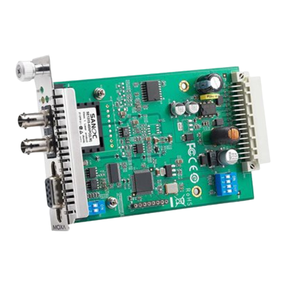
- Page 2 Overview Introduction The TCF-142-RM series fiber converters are slide-in modules that can be installed in the NRack System’s rackmount chassis, such as the TRC- 190 series. The slide-in module is equipped with a multiple interface circuit that can handle RS-232 or RS-422/485 serial interfaces, and multi-mode or single-mode fiber.
-
Page 3: Installation
Installation The media converter slide-in module can be hot-swapped, which means the chassis doesn’t have to power off or be removed during installation. Align the slide-in module with the chassis installation slot so that the panel fastener screw is at the top of the module. Carefully slide the slide-in module into the slot while aligning the module’s circuit board with the installation guide. - Page 4 Mounting Dimensions (Unit: mm) TCF-142-SC TCF-142-ST - 4 -...
-
Page 5: Fiber Cable
ATTENTION Electrostatic Discharge Warning! To protect the product from damage due to electrostatic discharge, we recommend wearing a grounding device when handling your TCF-142-RM-slide-in modules module series. Pin Assignment and Connector 9-pin D-sub Female RS-232 RS-422/485-4w RS-485-2w – RxD-(A) Data-(A) RxD+(B) Data+(B) TxD+(B) -
Page 6: Switch Settings
Switch Settings There are three sets of DIP switches on the board. One set for fiber and another for the connector. Following are the settings for the three connector DIP switches. Pin1 Pull High Pin 2 Pull Low Pin 3 Terminator 150 kilo- ohms 1 kilo-ohm... - Page 7 Pin1 Pin 2 Pin 3 Ring Point to Point The S3 DIP Switch is located inside the TCF-142-RM. When the TCF- 142-RM is in RS-485 mode, use this DIP switch to configure RS-485 data direction control, data format, and baudrate. When the TCF-142- RM is in RS-232/422 mode, the S3 DIP switch cannot affect RS- 232/422 communication.
-
Page 8: Led Indicators
LED Indicators There are three LEDs on the front bracket of the TCF-142-RM slide-in modules. Color Function Green Steady ON: Power is ON Fiber Tx Green When sending serial data from the fiber port Fiber Rx Yellow When receiving data from the fiber port Specifications Serial Communication Signals for RS-232... - Page 9 3 V/m EN 61000-4-8 (PFMF) EN 61000-4-11 (DIPS) Free fall IEC 60068-2-32 - 9 -...
Need help?
Do you have a question about the TCF-142-M-SC-RM and is the answer not in the manual?
Questions and answers