
Related Manuals for Moxa Technologies TCF-142-RM Series


Summary of Contents for Moxa Technologies TCF-142-RM Series
- Page 1 TCF-142-RM Series Hardware Installation Guide Third Edition, March 2015 2015 Moxa Inc. All rights reserved. P/N: 1802001420622 *1802001420622*...
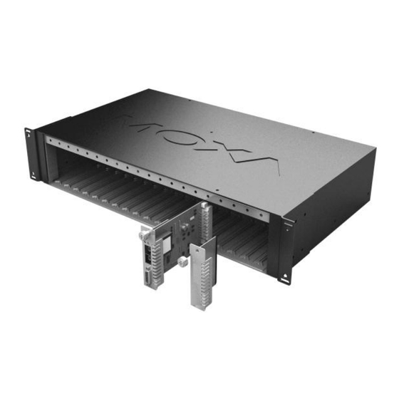
- Page 2 Overview Introduction The TCF-142-RM series fiber converters are slide-in modules that can be installed in the NRack System’s rackmount chassis, such as the TRC-190 series. The slide-in module is equipped with a multiple interface circuit that can handle RS-232 or RS-422/485 serial interfaces, and multi-mode or single-mode fiber.
- Page 3 Installation The media converter slide-in module can be hot-swapped, which means the chassis doesn’t have to power off or be removed during installation. Align the slide-in module with the chassis installation slot so that the panel fastener screw is at the top of the module. Carefully slide the slide-in module into the slot while aligning the module’s circuit board with the installation guide.
- Page 4 Mounting Dimensions (Unit: mm) TCF-142-SC TCF-142-ST - 4 -...
- Page 5 ATTENTION Electrostatic Discharge Warning! To protect the product from damage due to electrostatic discharge, we recommend wearing a grounding device when handling your TCF-142-RM-slide-in modules module series. Pin Assignment and Connector 9-pin D-sub Female RS-232 RS-422/485-4w RS-485-2w RxD-(A) Data-(A) RxD+(B) Data+(B) TxD+(B) TxD-(A)
- Page 6 Switch Settings There are 2 sets of DIP switches on the board. One set for fiber and another for the connector. Following are the settings for the 4 connector DIP switches. Serial Connection Switch 1 Switch 2 RS-232 ON (default) ON (default) RS-422 2-wire RS-485...
- Page 7 Following are the settings for the 2 fiber DIP switches. Switch 1 (Pull Low) Switch 2 (Pull High) 150KΩ 1KΩ ON (Default) ON (Default) LED Indicators There are 3 LEDs on the front bracket of the TCF-142-RM slide-in modules. Color Function Green Steady ON: Power is ON...
- Page 8 Environmental Operating Temperature 0 to 60°C (32 to 142°F), 5 to 95 % RH Storage Temperature -20 to 75°C (-4 to 185°F), 5 to 95 % RH Power Input Power Voltage 12 VDC Power Consumption 150 mA @ 12V Mechanical Dimensions (W ×...
Need help?
Do you have a question about the TCF-142-RM Series and is the answer not in the manual?
Questions and answers