Table of Contents
Advertisement
Thanks for you preference, and have a good time! This hand-
book contains the information you need to properly operate and
maintain your motorcycle.
The data and specifi cations provided in this manual does not constitute an
engagement on the part of BETAMOTOR S.p.A. BETAMOTOR reserves the
right to make any changes and improvements to its models at any moment
and without notice.
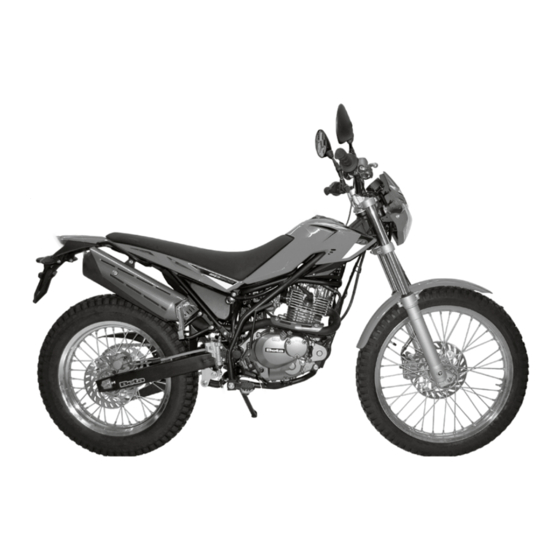
ALP 200
1
GB
Advertisement
Chapters
Table of Contents
Troubleshooting

Subscribe to Our Youtube Channel
Related Manuals for Beta ALP 200


Summary of Contents for Beta ALP 200
- Page 1 ALP 200 Thanks for you preference, and have a good time! This hand- book contains the information you need to properly operate and maintain your motorcycle. The data and specifi cations provided in this manual does not constitute an engagement on the part of BETAMOTOR S.p.A. BETAMOTOR reserves the right to make any changes and improvements to its models at any moment and without notice.
- Page 2 IMPORTANT We recommend checking all the tightenings after the fi rst one or two hours’ ride over rough ground. Special attention should be paid to the following parts: • rear sprocket • footrest supports • front brake caliper • mudguard bracket •...
-
Page 3: Table Of Contents
TABLE OF CONTENTS Operating instructions ................5 Ecologic guide ..................5 Riding safety ..................6 CHAPTER 1 GENERAL INFORMATION ..........7 Vehicle identifi cation data ............... 8 Familiarizing with the vehicle..............9 Specifi cations ..................10 Engine ....................12 Electrical system ................... 14 Recommended lubricants and liquids ............ - Page 4 Spark plug ..................40 Carburettor ..................40 Front brake..................41 Rear brake ..................43 Clutch control ..................44 Ckeck of steering play ................45 Tyres....................46 Fork oil ....................46 Chain ....................47 Headlight .................... 48 Turn indicators ..................49 Tail light ....................
-
Page 5: Operating Instructions
OPERATING INSTRUCTIONS • The vehicle must be accompanied by: number-plate, registration document, tax disc and insurance. • Do not carry animals, pets or loose objects that can stick out from the vehicle. • Riding without a crash helmet is forbidden. •... -
Page 6: Riding Safety
RIDING SAFETY • Observe the Highway Code. • Always put on and fasten a homologated helmet. • Always ride with the low beam on. • Always keep the crash helmet visor clean. • Avoid wearing garments with hanging ends. • Do not keep sharp or brittle objects in your pockets while riding. •... -
Page 7: Chapter 1 General Information
CHAPTER 1 GENERAL INFORMATION CONTENTS Vehicle identifi cation data ............... 8 Frame identifi cation ................8 Engine identifi cation ................8 Toolkit ....................8 Familiarizing with the vehicle..............9 Specifi cations ..................10 Weigth ................... 10 Vehicle dimensions ................10 Tyres .................... -
Page 8: Vehicle Identifi Cation Data
VEHICLE IDENTIFICATION DATA FRAME IDENTIFICATION Frame identifi cation data A are stamped on the right side of the steering head tube. ENGINE IDENTIFICATION Engine identifi cation data B are stamped in the area shown in the picture. TOOLKIT The following items are supplied as stand- ard: maintenance manual and tool kit (see picture). -
Page 9: Familiarizing With The Vehicle
FAMILIARIZING WITH THE VEHICLE Main parts: 1 - Air fi lter 8 - Rear light 15 - Engine protection 2 - Fuel tank 9 - Rear turn indicators 16 - Saddle 3 - Tank cap 10 - Side stand 17 - Engine 4 - Silencer 11 - Rearview mirror 18 - Front mudguard... -
Page 10: Specifi Cations
SPECIFICATIONS WEIGHT Dry weight .................103,0 kg front ...................49,5 kg rear ..................53,5 kg VEHICLE DIMENSIONS maximum length ................ 2143 mm maximum width ................820 mm wheelbase................1372 mm ground clearance ................ 288 mm saddle height ................836 mm TYRES TRIAL settings Dimensions Pressure [Bar] Front tyre... - Page 11 FRONT SUSPENSION Shaft diameter ................∅ 37mm Type of oil ..............AGIP ARNICA SA 32 Oil quantity ................0,552Kg REAR SUSPENSION Spring K ..................K12,5 Spring preload ................139mm FRONT BRAKE Ø 245 mm disc brake with hydraulic control REAR BRAKE Ø...
-
Page 12: Engine
ENGINE Type ................... 4 Stroke Bore x stroke ................ 66x58,2 mm Displacement (cm ) ...............199 cm Pressure ratio ................... 9,4:1 Fuel system ................carburetor CARBURETOR Carburetor type MIKUNI BST31 42AD Main jet 122.5 Slow jet Starter jet Needle 5D26 Needle position (from top)) 3°... - Page 13 TRANSMISSION Primary drive 60/19 Gear ratio 1st gear 33/11 Gear ratio 2nd gear 29/15 Gear ratio 3rd gear 23/16 Gear ratio 4th gear 23/21 Gear ratio 5th gear 21/23 Secondary drive 48/15 Starting .............electric starter and kickstart...
-
Page 14: Electrical System
ELECTRICAL SYSTEM ELECTRICAL DIAGRAM... -
Page 15: Legend Electrical Diagram
LEGEND ELECTRICAL DIAGRAM FRONT R.H. BLINKER WITH BULB 12V-6W FRONT STOP PUSH BUTTON ENGINE STOP STARTING BUTTON RIGHT CENTRAL UNIT WHEEL SPEED SENSOR BLINKERS TELL TALE LAMP BUTTON 1 DIODE 1A 10) DASHBOARD TRAILTECH 11) HIGH BEAM TELL TALE LAMP 12) NEUTRAL TELL TALE LAMP 13) BUTTON 2 14) LEFT CENTRAL UNIT... -
Page 16: Recommended Lubricants And Liquids
RECOMMENDED LUBRICANTS AND LIQUIDS For better operation and longer vehicle life, we advise you to use the products listed in the following chart: TYPE OF PRODUCT TECHNICAL SPECIFICATION TRANSMISSION OIL PANOLIN OFF ROAD 4T BLEND 10W/40 BRAKE OIL BRAKE FLUID DOT 4 FORK OIL AGIP ARNICA SA32 GREASE FOR RODS... -
Page 17: Chapter 2 Operation
CHAPTER 2 OPERATION CONTENTS Main parts ..................18 Fuel cock ..................18 Starter .................... 18 Clutch lever ..................18 Lh switch ..................19 Rh switch ..................19 Front brake lever and gas control ............19 Gearchange lever................20 Brake pedal ..................20 Kickstart .................. -
Page 18: Main Parts
MAIN PARTS FUEL COCK Fuel cock has three positions: OFF: fuel supply closed. Fuel cannot pass from the tank to the carburettor. ON: fuel supply enabled. Fuel fl ows from the tank to the carburettor. The tank empties until it reaches the reserve level. RES: reserve fuel supply. -
Page 19: Lh Switch
LH SWITCH The dip and service switch is located on the left side of the handlebar and is com- posed as follows: 1 Horn button; 2 Dip switch high beam ; low beam) 3 High beam switch; 4 Turn signal light switch: Shifting lever left or right activates the left or right indi- cators. -
Page 20: Gearchange Lever
GEARCHANGE LEVER Gearchange lever A is fi tted to the left side of the engine. The positions corresponding to the different gears are shown in the fi gure. BRAKE PEDAL Brake pedal A is located in front of the right-hand footrest. KICKSTART The kick-starter pedal is located on the right side of the engine. -
Page 21: Keys
KEYS The vehicle is supplied with two keys (one key and its spare), for the ignition switch/ steering lock and the helmet lock. - Turn the key to to start up the engine. - Turn the key to to switch off the en- gine. -
Page 22: Digital Rpm Indicator Operating Instructions
DIGITAL RPM INDICATOR OPERATING INSTRUCTIONS Contents 1 GENERAL SPECIFICATIONS AND GENERAL INFORMATIONS 1.1 General specifi cations 1.2 General informations 2 SETTING THE PARAMETERS 2.1 Setup sequence 2.1.1 Selecting the unit of measure 2.1.2 Selecting the wheel size 2.1.3 Selecting the clock format 2.1.4 Setting the Time 2.1.5 Selecting the maintenance memo 3 SCREENS... - Page 23 When using supplied power with the engine on: • The back-lighting is on permanently when the engine is running. Using only the internal battery: • With the LO symbol, the backlighting will not switch on. The symbol appears when the battery voltage is lower than 2.45V. Reset Button: Using the Reset button, located on the back of the instrument, all travel data will be deleted, including date and time.
- Page 24 2.1 SETUP SEQUENCE Select unit of measure Wheel size Clock format Setting the Time Maintenance reminder 2.1.1 Selecting the unit of measure (Km/h or M/h): TO SELECT THE UNIT OF MEASURE (Km/h or M/h), PRESS THE RIGHT OR LEFT BUTTON. WAIT 5 SECONDS TO PROCEED TO THE NEXT SETTING.
- Page 25 3 SCREENS Switching between 3 normal modes All of the information that the instrument is capable of providing is displayed on one of these 3 screens. The instrument will stay on the set screen until a button is pressed to switch to another screen.
- Page 26 5 SPEEDOMETER Speed The speed is displayed in the centre of screens 1 or 2 and can range from 0 to 399.9 km/h or M/h. The unit of measure (km/h or M/h) appears next to the speed reading. Maximum (Max) and Average (AVG) speed The Maximum (MAX) or Average (AVG) speeds are displayed on screen 3 to the left of the display.
- Page 27 Travelled distance (DST) The travelled distance can range from 0 to 9999.9 miles or kilometers and appears on the right side of screen 1. To clear the travelled distance, hold the right button down for 5 seconds. Note: you must be on screen 1 to clear the travelled distance. Travelled distance 2 (DST 2) Travelled distance 2 can range from 0 to 9999.9 miles or kilometers and appears on the right side of screen 2.
-
Page 28: Checks Before And After Use
CHECKS BEFORE AND AFTER USE For safe driving and long vehicle life you should: • Check all fl uid levels. • Check the correct operation of the brakes and brake pad wear (page 42). • Check pressure, general condition and thickness of tread (page 10). •... -
Page 29: Startup
STARTUP Set the fuel tank tap to ON or RES (see page 18). - Position the key to (see page 21). - Check that the gears are in neutral (page 20). - Pull the clutch lever (page 18). WARNING! If you do not pull the clutch lever the vehicle will not start. - Retract the stand (page 20). -
Page 30: Trial Trim Option
TRIAL TRIM OPTION The motorbike has been designed to change trim, depending on the driving require- ments. It is so fl exible that it’s like having two motorbikes into one: - Alp touring: to drive on or off road. - Alp trial: for extreme driving on rough ground. To set the motorbike in the Alp trial trim, remove the following parts: - the saddle, - the tank cover,... -
Page 31: Chapter 3 Adjustments
CHAPTER 3 ADJUSTMENTS CONTENTS Key to symbols..................32 Brakes ....................32 Front brake ..................32 Adjustment of gas clearance .............. 32 Adjusting the idle speed ............... 33 Handlebar ..................33 Rear shock absorber ................33 Adjusting the spring preload ............. 33 Headlight .................... -
Page 32: Key To Symbols
KEY TO SYMBOLS Tightening torque BRAKES FRONT BRAKE The front brake is disk type with hydraulic control. Use the adjusting nut 1 to vary the inter- vention point. WARNING: reduced play causes brake overheating leading to sudden lockup. ADJUSTMENT OF GAS CLEARANCE The throttle control cable should always have a 3-5 mm play. -
Page 33: Adjusting The Idle Speed
ADJUSTING THE IDLE SPEED The slow running should be adjusted when the engine is hot. Connect an electronic revolution counter to the spark plug ca- ble. Then use a screwdriver on register screw 1 to calibrate the minimum with 1600÷1700 rpm HANDLEBAR The handlebar can be adjusted by rotating it back and forth. -
Page 34: Headlight
HEADLIGHT •The beam is adjusted by loosening the left and right fi xing screws 1 of the mask and changing the inclination of the opti- cal unit by turning the screws 2. •Place the vehicle on level ground (but not on the stand) 10 metres from a verti- cal wall. -
Page 35: Chapter 4 Checks And Maintenance
CHAPTER 4 CHECKS AND MAINTENANCE CONTENTS Engine oil .................... 36 Check the level ................36 Replacement ................... 36 Fume collecting tube ................37 Air fi lter ....................38 Removing and fi tting air fi lter ............38 Air fi lter cleaning ................39 Spark plug .................. -
Page 36: Engine Oil
ENGINE OIL CHECK THE LEVEL When engine is cold check the oil level by means of porthole 1. The oil level must be always visible from the porthole. In contrary case restore the oil level through cap 2. Use the oil indicated on page 16 in the “Recommended lubricants and liquids”... -
Page 37: Fume Collecting Tube
- Pour in the quantity of liquid indicated on page 10. - Screw on fi ller cap 1 again. - Start the engine and run at idle for a few minutes. - Turn off the engine and wait for about one minute, then check the level and top up if needed. -
Page 38: Air Filter
AIR FILTER Check after every ride. REMOVING AND FITTING AIR FILTER Remove the saddle, the tank cover and the under-saddle plastic shield, as described in “Body disassembly and reassembly” on page 58. • Remove the cover 2 by loosening the screw 3. -
Page 39: Air Fi Lter Cleaning
AIR FILTER CLEANING • Thoroughly wash the fi lter with water and soap. • Dry the fi lter. • Wet the filter with filter oil and then remove the excess oil to prevent it from dripping. • If necessary also clean the interior of the fi... -
Page 40: Spark Plug
SPARK PLUG Keeping the spark plug in good condition will reduce fuel consumption and increase engine performance. To perform the check, simply slide off the electrical connection tube and unscrew the spark plug. Examine the distance between the electrodes with a feeler. This distance should be from 0.5 to 0.6 mm. -
Page 41: Front Brake
WARNING: Fuel is fl ammable and toxic and must be handled with great care. Never work on the fuel system near heat sources or open fl ames. Always allow the engine to cool down before working on the fuel system. Wipe off any excess fuel with a rag. Materi- als soaked in fuel are also fl... -
Page 42: Bleeding The Front Brake
BLEEDING THE FRONT BRAKE To bleed air from the front brake circuit, proceed as follows: •Remove the rubber cap 1 from the valve •Open the sump cap. •Insert one end of a transparent tube into a container. •Pump with the brake lever 2/3 times and keep the lever pressed. -
Page 43: Rear Brake
REAR BRAKE CHECK THE LEVEL OF THE REAR BRAKE FLUID Check the level of the brake fl uid through sight 1. The level of the fl uid should never fall below the mark in the sight. RESTORING THE LEVEL OF THE REAR BRAKE FLUID To restore the oil level, top up by means of oil fi... -
Page 44: Clutch Control
REAR BRAKE LINING CONTROL 2 mm In order to verify the wear condition of rear brake is enough to view the caliper from the back side, where is possible to glimpse the brake lining tails which will have to show a brake of 2 mm in thickness. If the stratum is lesser let’s start replacing them. -
Page 45: Ckeck Of Steering Play
CHECK OF STEERING PLAY Periodically check the play in the steering sleeve by moving the fork back and forth as shown in the fi gure. Whenever you feel play, adjust as described below: - Loosen the screws 1 40Nm - Loosen nut 2 - Reduce the play by turning ring 3 Tighten the bolts to the prescribed torque values. -
Page 46: Tyres
FORK OIL The procedure for changing the oil in the forks is provided only for information. We recommend having the operation performed by a BETAMOTOR authorized workshop. Follow these steps to renew the oil: - Position the vehicle on the central bike stand. -
Page 47: Chain
CHAIN Checking the drive chain periodically to ensure longer chain life. Always keep it lubricated and clean of deposited dirt. If play exceeds 20 mm adjust the chain. 20 mm Take special care in preventing the lubri- cant from coming into contact with the rear tyre or brake disc, otherwise the tyre grip and the action of the brake would be greatly reduced, making it very diffi... -
Page 48: Headlight
HEADLIGHT Keep the headlight glass clean at all times (see page 53). Periodically check the correct angle of the light beam (chapter 3). REPLACING THE HEADLIGHT BULBS • Remove the two screws 1 and 2 that secure the light unit to the light holder. •... -
Page 49: Turn Indicators
TURN INDICATORS To reach the bulb, remove the glass cover by loosening screw A. Remove the bulb from the connectors and carry out replacement. TAIL LIGHT Keep the headlight glass clean at all times (see page 53). The LED tail light is sealed. In the case of burnout of one or more LEDs it is necessary to replace the entire group. -
Page 50: Removal
REMOVAL Remove the saddle, the tank cover and the undersaddle plastic shield, as described in “Body disassembly and reassembly” on page 58 . Remove the cover 2 by loosening the screw 3. Release rubber band. FIRST disconnect the negative connector (black) from negative (-) pole and THEN positive connector (black) from negative (+) pole. -
Page 51: Inactivity
INACTIVITY If the vehicle is not going to be used for a long time, remove the battery and charge it every 15 days using a suitable charger. Store the battery in a dry place at a tem- perature of 5 to 35°C and out of the reach of children. -
Page 52: Fuse
FUSE Fuse 1 is located in starting relay 2. To access the fuse remove the relay from the rubber mounting and release connec- tor 3. A spare fuse is supplied. A blown fuse should only be replaced with another of the same type. Should the new fuse also burn out when fi... -
Page 53: Cleaning The Vehicle
CLEANING THE VEHICLE WARNING: Do not clean your vehicle with a high-pressure device with a strong jet of water. Excessive pressure can reach electrical components, connectors, fl exible cables, bearings, etc and can damage or destroy them. WARNING: Wash motorbikes frequently that are used near the sea (salty air) and on roads subject to salt spreading in winter. -
Page 54: Prolonged Inactivity
PROLONGED INACTIVITY A few simple operations should be performed to keep the vehicle in good condition whenever it is to remain inactive for a long period (e.g. during the winter): • Thoroughly clean the vehicle. • Reduce the tyre pressures by approximately 30 percent, and if possible raise the tyres off the ground. -
Page 55: Scheduled Maintenance Vehicle
SCHEDULED MAINTENANCE VEHICLE Engine Spark plug Engine oil fi lter Clutch Valve clearance Engine oil and oil fi lter Idling setting Engine oil pipes Vehicle Rear shock absorber Battery Nuts and bolts Steering bearings and steering play Clean every Air fi lter (paper) 1000 Km Front fork Electrical system... -
Page 57: Chapter 5 Body Disassembly And Reassembly
CHAPTER 5 BODY DISASSEMBLY AND REASSEMBLY CONTENTS Removal and refi tting of the saddle............58 Removal and refi tting of the tank fairing ..........58 Removal and refi tting of the passenger handles ..........58 Removal and refi tting of the under-saddle plastic shield ......59... -
Page 58: Removal And Refi Tting Of The Saddle
REMOVAL AND REFITTING OF THE SADDLE Remove the screws indicated in fi gure. Remove the saddle towards the rear of the motorcycle. Reassemble proceeding in the reverse order. REMOVAL AND REFITTING OF THE TANK FAIRING After removing the saddle it is possible to remove the tank fairing. -
Page 59: Removal And Refi Tting Of The Under-Saddle Plastic Shield
REMOVAL AND REFITTING OF THE UNDER-SADDLE PLASTIC SHIELD After removing the saddle, the tank cover and the passenger handles, the under- saddle plastic shield 1 can be removed. Remove the screw indicated in fi gure. Remove the under-saddle 1 towards the rear of the motorcycle. -
Page 61: Chapter 6 Troubleshooting
CHAPTER 6 TROUBLESHOOTING CONTENTS Troubleshooting ................... 62 Alphabetical index ................63... -
Page 62: Troubleshooting
TROUBLESHOOTING PROBLEM CAUSE REMEDY The electric starter does Key in position Move the key on not turn Flat battery Check the battery Blown fuse Replace Defective relay Contact authorised BETAMOTOR customer service Defective starter motor Contact authorised BETAMOTOR customer service The engine turns over but will Fuel cock in OFF position Move the fuel cock to ON or RES position... - Page 63 ALPHABETICAL INDEX Adjusting the idle speed ............... 33 Air fi lter ....................38 Battery ....................49 Brakes ....................32 Breaking in..................28 Carburettor ..................40 Chain ....................47 Checks before and after use ..............28 Check of steering play ................45 Cleaning the vehicle ................
- Page 64 Operating instructions ................5 Prolonged inactivity ................54 Rear brake ..................43 Rear shock absorber ................33 Recommended lubricants and liquids ............16 Removal and refi tting of the passenger handles ..........58 Removal and refi tting of the saddle............58 Removal and refi...
Need help?
Do you have a question about the ALP 200 and is the answer not in the manual?
Questions and answers