Table of Contents
Advertisement
Thanks for you preference, and have a good time! This hand-
book contains the information you need to properly operate and
maintain your motorcycle.
The data, specifications and images shown in this manual does not constitute
an engagement on the part of BETAMOTOR S.p.A. BETAMOTOR reserves
the right to make any changes and improvements to its models at any mo-
ment and without notice.
ALP 200
Code 017.44.018.83.00
1
EN
Advertisement
Chapters
Table of Contents
Troubleshooting

Related Manuals for Beta Alp 200


Summary of Contents for Beta Alp 200
- Page 1 ALP 200 Thanks for you preference, and have a good time! This hand- book contains the information you need to properly operate and maintain your motorcycle. The data, specifications and images shown in this manual does not constitute an engagement on the part of BETAMOTOR S.p.A. BETAMOTOR reserves the right to make any changes and improvements to its models at any mo- ment and without notice.
- Page 2 IMPORTANT We recommend checking all the tightenings after the first one or two hours’ ride over rough ground. Special attention should be paid to the following parts: • rear sprocket • ensure that the footrests are properly fixed • front/rear brake levers/calipers/discs •...
-
Page 3: Table Of Contents
TABLE OF CONTENTS Operating instructions ................5 Symbols ....................5 Riding safety ..................6 CHAPTER 1 GENERAL INFORMATION ..........7 Vehicle identification data ............... 8 Familiarizing with the vehicle..............9 Specifications ..................10 Engine ....................12 Electrical system ................... 14 Bulbs .................... - Page 4 Petrol fumes exhaust pipe ..............39 Air filter ....................40 Spark plug ..................42 Carburettor ..................42 Front brake..................43 Rear brake ..................45 Check and adjustment of steering play ........... 47 Front wheel ..................48 Fork ....................49 Rear suspension leverage ..............49 Tyres....................
-
Page 5: Operating Instructions
OPERATING INSTRUCTIONS • The vehicle must be accompanied by: number-plate, registration document, tax disc and insurance. • Any modifications of the engine or other parts are punishable by severe sanctions including the confiscation of the vehicle. • To protect your safety and that of others, always drive carefully and with your helmet on and always keep low beams on. -
Page 6: Riding Safety
RIDING SAFETY • Observe the Highway Code. • Always wear approved personal protective equipment. • Always ride with the low beam on. • Always keep the crash helmet visor clean. • Avoid wearing garments with hanging ends. • Do not keep sharp or brittle objects in your pockets while riding. •... -
Page 7: Chapter 1 General Information
CHAPTER 1 GENERAL INFORMATION CONTENTS Vehicle identification data ............... 8 Frame identification ................8 Engine identification ................8 Toolkit ....................8 Familiarizing with the vehicle..............9 Specifications ..................10 Weight ................... 10 Vehicle dimensions ................10 Tyres ....................10 Capacities ..................10 Front suspension ................ -
Page 8: Vehicle Identification Data
VEHICLE IDENTIFICATION DATA FRAME IDENTIFICATION Frame identification data A are stamped on the right side of the steering head tube. ENGINE IDENTIFICATION Engine identification data B are stamped in the area shown in the picture. TOOLKIT The following items are supplied as stand- ard: maintenance manual and tool kit (see picture). -
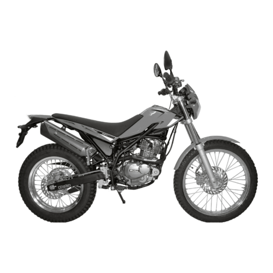
Page 9: Familiarizing With The Vehicle
FAMILIARIZING WITH THE VEHICLE Main parts: 1 - Air filter 8 - Rear light 15 - Engine protection 2 - Fuel tank 9 - Rear turn indicators 16 - Saddle 3 - Tank cap 10 - Side stand 17 - Engine 4 - Silencer 11 - Rearview mirror 18 - Front mudguard... -
Page 10: Specifications
SPECIFICATIONS WEIGHT Weight in running order with full fuel and optional ......118 kg front ..................57 kg rear ..................61 kg VEHICLE DIMENSIONS maximum length ................ 2125 mm maximum width ................820 mm wheelbase................1355 mm ground clearance ................ 350 mm saddle height ................900 mm TYRES Dimensions Pressure [Bar]... -
Page 11: Front Suspension
FRONT SUSPENSION Shaft diameter ................∅ 37mm Type of oil ..................SAE 15 Oil quantity (for each stem) ..............280ml REAR SUSPENSION Spring K ..................K12,5 Spring preload ................139mm FRONT BRAKE Ø 245 mm disc brake with hydraulic control REAR BRAKE Ø... -
Page 12: Engine
ENGINE Type ..............single-cylinder, 4-stroke Bore x stroke [mm] ..............66x58,2 Displacement [cm ] ................199 Pressure ratio ................... 9,4:1 CO2 * ..................76 g/km Fuel consumption * ............... 3,4 l/100km Fuel system ................carburetor CARBURETOR Carburetor type MIKUNI BST31 42AD Cooling system ................Air-cooled Spark plug ................NGK DR8 EA Clutch .................. -
Page 13: Transmission
TRANSMISSION Primary drive 60/19 Gear ratio 1st gear 33/11 Gear ratio 2nd gear 29/15 Gear ratio 3rd gear 23/16 Gear ratio 4th gear 23/21 Gear ratio 5th gear 21/23 Secondary drive 48/15 Starting .............electric starter and kickstart... -
Page 14: Electrical System
ELECTRICAL SYSTEM ELECTRICAL DIAGRAM... -
Page 15: Legend Electrical Diagram
LEGEND ELECTRICAL DIAGRAM FRONT STOP PUSH BUTTON FRONT R.H. BLINKER WITH BULB 12V-6W RIGHT CONTROL SWITCH ENGINE STOP BUTTON STARTING BUTTON SPEED SENSOR ENGINE DIAGNOSIS TELL TALE LAMP RIGHT SIDE BLINKERS TELL TALE LAMP NEUTRAL TELL TALE LAMP DASHBOARD HIGH BEAM TELL TALE LAMP LEFT SIDE BLINKERS TELL TALE LAMP HORN BUTTON FLASH BUTTON... -
Page 16: Bulbs
BULBS High beam/low beam ...........H4 12V - 60/55W Parking/daytime ..............12V - W5W Turn indicators ................ 12V - H6W License plate light ..............12V - W5W Fuses (two) ..................20A RECOMMENDED LUBRICANTS AND LIQUIDS For better operation and longer vehicle life, we advise you to use the products listed in the following chart: TYPE OF PRODUCT TECHNICAL SPECIFICATION... -
Page 17: Chapter 2 Operation
CHAPTER 2 OPERATION CONTENTS Main parts ..................18 Fuel cock ..................18 Starter .................... 18 Clutch lever ..................18 Lh switch ..................19 Rh switch ..................19 Front brake lever and gas control ............19 Gearchange lever................20 Brake pedal ..................20 Kickstart .................. -
Page 18: Main Parts
MAIN PARTS FUEL COCK Fuel cock has three positions: OFF: fuel supply closed. Fuel cannot pass from the tank to the carburettor. ON: fuel supply enabled. Fuel flows from the tank to the carburettor. The tank empties until it reaches the reserve level. RES: reserve fuel supply. -
Page 19: Lh Switch
LH SWITCH The dip and service switch is located on the left side of the handlebar and is com- posed as follows: 1 Horn button; 2 Dip switch high beam ; low beam) 3 High beam switch; 4 Turn signal light switch: Shifting lever left or right activates the left or right indi- cators. -
Page 20: Gearchange Lever
GEARCHANGE LEVER Gearchange lever is fitted to the left side of the engine. The positions corresponding to the different gears are shown in the figure. BRAKE PEDAL Brake pedal A is located in front of the right-hand footrest. KICKSTART The kick-starter pedal is located on the right side of the engine. -
Page 21: Keys
KEYS The vehicle is supplied with two keys (one key and its spare), for the ignition switch/ steering lock and the helmet lock. - Turn the key to to start up the engine. - Turn the key to to switch off the en- gine. -
Page 22: Dashboard Operating Instructions
DASHBOARD OPERATING INSTRUCTIONS MAIN PARTS Time Clock: 12/24 MODE Stopwatch: According to setup distance to record the testing time. Speed Log: Average speed and max Speedometer speed record. Display range: 0~360km/h (0~225 MPH) Display unit: km/h or MPH Battery Inner Battery Level: Display range: 4 levels. -
Page 23: Warning Lights
WARNING LIGHTS 1 Headlight indicator The system activates the indi- cator in synchrony with the ac- tivation of the mains beams. 2 Turn indicator lights The system activates the indi- cator in synchrony with the ac- tivation of the turn indicators. 3 Neutral indicator light The system activates the indicator in synchrony with the engaging of the neutral. -
Page 24: Adjust Button Function Instruction
ADJUST BUTTON FUNCTION INSTRUCTION In main screen, press the Adjust button once to switch the function from odometer to trip. In main screen, you could hold pressing the Adjust button for 3 seconds to change the speed unit. Press the Adjust button to switch from trip A to trip B. -
Page 25: Select Button Function Instruction
Press the Adjust button to switch from Hour Meter B back to the main screen. Press and hold the Adjust button for 3 seconds to reset the Hour Meter B The main screen. SELECT BUTTON FUNCTION INSTRUCTION Press the Select button during main screen to switch from Clock to Stopwatch. -
Page 26: To Enter The Setting Mode
TO ENTER THE SETTING MODE Adjust+SelectX3 function instruction In main screen, press down the Adjust+SelectX3 to enter the tire circum- ference and sensing point setting (for changing different size tire.) The tire circumference and sensor point setting. Press the Adjust button to enter the tire circumference setting. - Page 27 The clock (Hour) setting EX: You want to set the hour at 14. Press the Select button to choose the hour you want to set. NOTE: Setting range: 0~23 H. NOTE: The sequent of cursor movement: Hour>Ten-Digit of Minute>Single Digit of Minute EX.
- Page 28 Switch from Press Select button to switch to Engine Oil Light Mileage setting screen. Press Adjust button to enter the Engine Oil Light Mileage setting. Maintenance Light Mileage Setting Press the Select button to choose mainte- nance mileage ON or OFF. NOTE: Default: OFF If ON is chosen, press Adjust button to enter the maintenance mileage setting...
- Page 29 Backlight brightness Press the Select button to adjust the bright- ness of the backlight NOTE: Adjustable Range: 1 ~ 5 NOTE: Default: 5 Press the Adjust button to exist from the Backlight Brightness setting. From switch to screen Press Adjust button to enter the mileage setting.
-
Page 30: Checks Before And After Use
CHECKS BEFORE AND AFTER USE For safe driving and long vehicle life you should: 1 Check all fluid levels. (page 44). 2 Check the correct operation of the brakes and brake pad wear (page 10). 3 Check pressure, general condition and thickness of tread 4 Check that the spokes are properly tightened. -
Page 31: Fuelling
FUELLING See page 16 for the fuel specifications. Disconnect the ventilation pipe 1. To open the tank turn the cap 2 anticlock- wise. To close the fuel tank’s cap, set it on the tank and crew it clockwise. WARNING! Refuelling must be carried out with the engine switched off. WARNING Fire hazard. -
Page 32: Startup
STARTUP Set the fuel tank tap to ON or RES (see page 18). - Position the key to (see page 21). - Make sure the right switch on the handlebar is on (page 19) - Check that the gears are in neutral (page 20). - Pull the clutch lever (page 18). -
Page 33: Chapter 3 Adjustments
CHAPTER 3 ADJUSTMENTS CONTENTS Key to symbols..................34 Brakes ....................34 Front brake ..................34 Rear brake ..................34 Adjustment of clutch lever ..............34 Adjustment of gas clearance ..............35 Adjusting the idle speed ............... 35 Handlebar ..................35 Rear shock absorber ................ -
Page 34: Key To Symbols
KEY TO SYMBOLS Tightening torque BRAKES FRONT BRAKE The front brake is disk type with hydraulic control. Use the adjusting nut 1 to vary the inter- vention point. WARNING: reduced play causes brake overheating leading to sudden lockup. REAR BRAKE The home position of brake pedal can be altered by turning adjusting screw 1. -
Page 35: Adjustment Of Gas Clearance
ADJUSTMENT OF GAS CLEARANCE The throttle control cable should always have a 3-5 mm play. In addition, the idle speed should not change when the han- dlebars are fully rotated to the left or right. Push back protective cap 1. Loosen counternut 2 and turn adjusting screw 3. -
Page 36: Headlight
HEADLIGHT •The light beam is adjusted by unscrewing or tightening screw A. By tightening screw the light beam is lowered; loosening screw raises the light beam. •Place the vehicle on level ground (but not on the stand) 10 metres from a verti- cal wall. •Measure the height of the headlight cen- tre above the ground and then draw a cross on the wall at 9/10 of the height of the headlight centre. -
Page 37: Chapter 4 Checks And Maintenance
CHAPTER 4 CHECKS AND MAINTENANCE CONTENTS Engine oil .................... 38 Check the level ................38 Replacement ................... 38 Fume collecting tube ................39 Petrol fumes exhaust pipe ..............39 Air filter ....................40 Removing and fitting air filter ............40 Air filter cleaning ................ -
Page 38: Engine Oil
ENGINE OIL CHECK THE LEVEL When engine is cold check the oil level by means of porthole 1. The oil level must be always visible from the porthole. In contrary case restore the oil level through cap 2. Use the oil indicated on page 16 in the “Recommended lubricants and liquids”... -
Page 39: Fume Collecting Tube
- Pour in the quantity of liquid indicated on page 16. - Screw on filler cap 1 again. - Start the engine and run at idle for a few minutes. - Turn off the engine and wait for about one minute, then check the level and top up if needed. -
Page 40: Air Filter
WARNING Fire hazard. Fuel is highly flammable. Pay special attention so that the fuel does not come into contact with hot parts of the vehicle. Immediately clean up any spilled fuel. : Risk of poisoning. WARNING Fuel is poisonous liquid and a health hazard. Fuel must not come into contact with the skin, eyes, and clothing. -
Page 41: Air Filter Cleaning
• Release the filter holder 4. • Remove the filter unit 1. WARNING: After every intervention, check that nothing has been left inside the filter box. Reassemble following the dismantling sequence in inverse order. WARNING: Never use the vehicle if the air filter is not in place. -
Page 42: Spark Plug
SPARK PLUG Keeping the spark plug in good condition will reduce fuel consumption and increase engine performance. To perform the check, simply slide off the electrical connection tube and unscrew the spark plug. Examine the distance between the electrodes with a feeler. This distance should be from 0.5 to 0.6 mm. -
Page 43: Front Brake
WARNING: Follow action on a cold engine. WARNING: Fire hazard! Fuel is highly flam- mable. Always stop the engine when refuelling and keep open flames and lighted cigarettes away. Immediately clean up any spilled fuel. FRONT BRAKE CHECK THE LEVEL OF THE FRONT BRAKE FLUID Check the level of the brake fluid through sight A. -
Page 44: Bleeding The Front Brake
BLEEDING THE FRONT BRAKE To bleed air from the front brake circuit, proceed as follows: •Remove the rubber cap 1 from the valve •Open the sump cap. •Insert one end of a transparent tube into a container. •Pump with the brake lever 2/3 times and keep the lever pressed. •Unscrew the valve and let the oil drain. •If are still visible in the tube repeat above operation until obtaining a continuous outflow of oil within no air bubbles. •Close the valve and release the lever. -
Page 45: Rear Brake
BRAKE DISC THICKNESS CONTROL Periodically verify disc condition. In case signs of damage , veins, or deformations are present, proceed with replacement. Verify disc thickness. The minimum thick- ness is engraved on the disc. Once the limit is in proximity or has been reached, proceed with brake disc replace- ment. -
Page 46: Rear Brake Lining Control
BLEEDING THE REAR BRAKE To bleed air from the rear brake circuit, proceed as follows: •Remove the rubber cap 1 from the valve •Open the sump cap. •Insert one end of a transparent tube into a container. •Pump with the brake lever 2/3 times and keep the lever pressed. •Unscrew the valve and let the oil drain. •If are still visible in the tube repeat above operation until obtaining a continuous outflow of oil within no air bubbles. -
Page 47: Check And Adjustment Of Steering Play
BRAKE DISC THICKNESS CONTROL Periodically verify disc condition. In case signs of damage , veins, or deformations are present, proceed with replacement. Verify disc thickness. The minimum thick- ness is engraved on the disc. Once the limit is in proximity or has been reached, proceed with brake disc replace- ment. -
Page 48: Front Wheel
FRONT WHEEL TIGHTENING Following removal of the wheel: Compress and release the fork 3-4 times. - Tighten the wheel bolt and the screws of the foot-leg. 10Nm 100Nm... -
Page 49: Fork
FORK To maintenance refer at an authorized service centre Betamotor. To check the tightening torques see as shown in the figure. WARNING: Tightening of the screws should be carried out by adjusting the torque 20Nm wrench to the stability torque with repeated tightening until stability torque has been achieved. -
Page 50: Tyres
TYRES Only fit tyres approved by BETAMOTOR. Unsuitable tyres can adversely affect the road holding of the vehicle. • To protect your safety, immediately replace any damaged tyres. • Slick tyres adversely affect the road holding of the vehicle, especially on wet roads and in off-road riding. -
Page 51: Chain
CHAIN Checking the drive chain periodically to ensure longer chain life. Always keep it lubricated and clean of deposited dirt. If play exceeds 20 mm adjust the chain. 20 mm Take special care in preventing the lubri- cant from coming into contact with the rear tyre or brake disc, otherwise the tyre grip and the action of the brake would be greatly reduced, making it very difficult to... -
Page 52: Headlight
HEADLIGHT Keep the headlight glass clean at all times (see page 57). Periodically check the correct angle of the light beam (chapter 3). REPLACING THE HEADLIGHT BULBS Remove the fixing screws and move for- ward the lamp holder front cowl. Carefully remove lamp 1 complete with the lamp holder. -
Page 53: Turn Indicators
TURN INDICATORS To reach the bulb, remove the glass cover by loosening screw A. Remove the bulb from the connectors and carry out replacement. TAIL LIGHT Keep the headlight glass clean at all times (see page 57). The LED tail light is sealed. In the case of burnout of one or more LEDs it is necessary to replace the entire group. -
Page 54: Battery
BATTERY Battery is located under the saddle and requires no maintenance. Keep the battery terminals clean. If neces- sary, protect them with a thin film of acid- free grease. REMOVAL Remove the saddle, the tank cover and the undersaddle plastic shield, as described in “Body disassembly and reassembly”... -
Page 55: Inactivity
Should the electrolyte come into contact with the eyes, rinse with water for at least 15 minutes and immediately seek medical attention. Even though the battery is sealed, there is a possibility that explosive gases may leak out. Keep sparks and open flames away from he battery. Keep spent batteries out of the reach of children and dispose of them as prescribed by law. -
Page 56: Fuses
FUSES The vehicle has a fuses set located under the right side panel. To reach it: - remove the right side panel 1 (page 62). - remove the protective cap. Fuse 2 (10A) protects the electrical services circuit. Fuse 3 (10A) is a spare one. In case of fuse failure: - the vehicle stops/does not start. -
Page 57: Cleaning The Vehicle
CLEANING THE VEHICLE GENERAL PRECAUTIONS WARNING: Do not clean your vehicle with a high-pressure device with a strong jet of water. Excessive pressure can reach electrical components, con- nectors, flexible cables, bearings, etc and can damage or destroy them. WARNING: Wash motorbikes frequently with cold water that are used near the sea (salty air) and on roads subject to salt spreading in winter. -
Page 58: Prolonged Inactivity
PROLONGED INACTIVITY A few simple operations should be performed to keep the vehicle in good condition whenever it is to remain inactive for a long period (e.g. during the winter): • Thoroughly clean the vehicle. • Reduce the tyre pressures by approximately 30 percent, and if possible raise the tyres off the ground. -
Page 59: Scheduled Maintenance Vehicle
SCHEDULED MAINTENANCE VEHICLE Engine Spark plug Engine oil filter Clutch Valve clearance Engine oil and oil filter Idling setting Vehicle Rear shock absorber Battery Nuts and bolts Steering bearings and steering play Clean every Air filter (paper) 1000 Km Fork Electrical system/lights Braking system Brake fluid (renew every 2 years) -
Page 61: Chapter 5 Body Disassembly And Reassembly
CHAPTER 5 BODY DISASSEMBLY AND REASSEMBLY CONTENTS Removal and refitting of the saddle............62 Removal and refitting of the tank fairing ..........62 Removal and refitting right side panel ............. 62 Removal and refitting of the passenger handles ..........63 Removal and refitting of the under-saddle plastic shield ......63... -
Page 62: Removal And Refitting Of The Saddle
REMOVAL AND REFITTING OF THE SADDLE Remove the screws indicated in figure. Remove the saddle towards the rear of the motorcycle. Reassemble proceeding in the reverse order. REMOVAL AND REFITTING OF THE TANK FAIRING After removing the saddle it is possible to remove the tank fairing. -
Page 63: Removal And Refitting Of The Passenger Handles
REMOVAL AND REFITTING OF THE PASSENGER HANDLES After removing the saddle it is possible to remove the two passenger handles 1. Remove the screws indicated in figure. Remove the handles. Reassemble proceeding in the reverse order. REMOVAL AND REFITTING OF THE UNDER-SADDLE PLASTIC SHIELD After removing the saddle, the tank cover and the passenger handles, the under-... -
Page 65: Chapter 6 Troubleshooting
CHAPTER 6 TROUBLESHOOTING CONTENTS Troubleshooting ................... 66 Alphabetical index ................67... -
Page 66: Troubleshooting
TROUBLESHOOTING PROBLEM CAUSE REMEDY The engine starts but the Engine management system fault Contact authorised BETAMOTOR customer telltale “MIL” lights on service The electric starter does Key in position Move the key on not turn Flat battery Check the battery Blown fuse Replace Defective relay... - Page 67 ALPHABETICAL INDEX Adjusting the idle speed ............... 35 Adjustment of clutch lever ..............34 Adjustment of gas clearance ..............35 Air filter ....................40 Battery ....................54 Brakes ....................34 Breaking in..................30 Bulbs ....................16 Carburettor ..................42 Chain ....................51 Check and adjustment of steering play ...........
- Page 68 Main parts ..................18 Operating instructions ................5 Petrol fumes exhaust pipe ..............39 Plate light .................... 53 Prolonged inactivity ................58 Rear brake ..................45 Rear shock absorber ................35 Rear suspension leverage ..............49 Recommended lubricants and liquids ............16 Removal and refitting of the passenger handles ..........63 Removal and refitting of the saddle............
Need help?
Do you have a question about the Alp 200 and is the answer not in the manual?
Questions and answers
how much oil should be in the engine