Raymarine RC435 Owner's Handbook Manual
Hide thumbs
Also See for RC435:
- Owner's handbook manual (128 pages) ,
- Owner's handbook manual (128 pages)

Related Manuals for Raymarine RC435


Summary of Contents for Raymarine RC435
- Page 1 RC435 & RC435i Chartplotters Owner’s Handbook Document Number: 81236-2 Date: August 2004...
- Page 2 RC435 and RC435i Chartplotters...
-
Page 3: About This Handbook
NMEA 0183 interface. You can also download waypoints and routes to the RC435/435i from an external source. Note: This handbook contains important information about installing, using and maintaining your new Raymarine product. To get the best from the product, please read this handbook thoroughly. Conventions Used Throughout this handbook, dedicated buttons are referred to in bold capitals (for example, ENTER). -
Page 4: Important Information
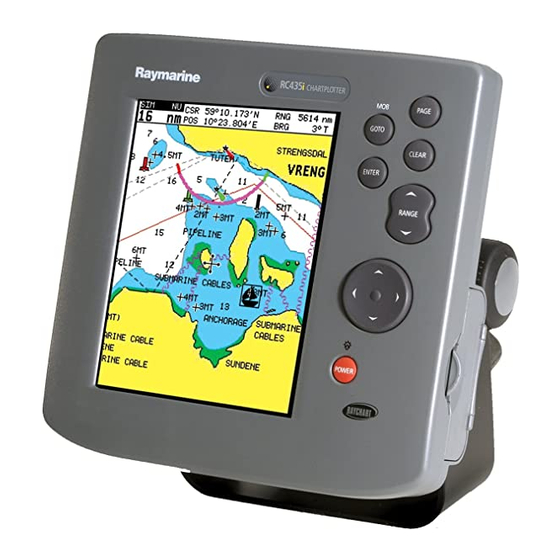
Intended Use The Raymarine RC435 is a chartplotter display unit with a built-in GPS receiver and external GPS antenna. The Raymarine RC435i version of the chartplotter display contains an internal GPS antenna. Both units are intended for marine navigation purposes on recreational boats. -
Page 5: Gps Reception
RC435i should never be mounted below deck or panel (flush) mounted. The optional Panel Mounting Kit listed in the handbook applies to the RC435 with External Antenna only. Failure to properly mount the chartplotter can result in poor performance. - Page 6 RC435 and RC435i Chartplotters Raymarine Products and Services Raymarine products are supported by a network of Authorized Service Representatives. Raymarine’s Technical Services representatives or your local dealer will be available to answer any questions you may have. For information on Raymarine products and services, contact either of the...
-
Page 7: Table Of Contents
2.2 Unpacking and Inspecting the Components ......... 8 Items Missing? ................8 Optional Items ................8 2.3 Installing the RC435 External GPS Antenna ........ 9 Special Instructions for Installing the RC435i ......9 Surface Mounting the External GPS Antenna ......10 Pole Mounting the External GPS Antenna ........ - Page 8 RC435 and RC435i Chartplotters System Check ................19 Initial Switch On ................. 19 Checking Chartplotter Operation ..........20 Chapter 3: Getting Started ................21 Introduction ................21 Simulator ..................21 Switching On/Off ................ 22 Changing the Lighting and Contrast ........... 22 Simulator Mode ................
- Page 9 Anchor Alarm ................42 XTE Alarm ................. 42 Select Chart ................. 42 Chart Text ................... 42 Chart Boundaries ................ 43 Safety Contours ................43 Depth Contours ................43 Spot Soundings ................43 Light Sectors ................43 Presentation ................43 Position Calibration ..............43 4.4 GPS Setup ...................
- Page 10 Servicing and Safety ..............105 Resetting the System ..............106 Problem Solving ............... 107 Troubleshooting ................ 107 How to Contact Raymarine ............108 On the Internet ................108 Customer Support ..............108 In the US ................... 108 In Europe ................... 110 Worldwide Support ..............
-
Page 11: Chapter 1: Overview
Chapter 1: Overview Chapter 1: Overview 1.1 RC435 and 435i Chartplotters Display Features and Functions The RC435/435i Chartplotter includes the following features: • Detailed navigation information from installed Navionics Gold ® Chart card • Positional information from Satellite Differential GPS •... -
Page 12: Trackpad And Cursor
POWER toggles the unit on and off. Cursor Vessel Symbol Primary function bar Figure 1-1: RC435/435i Chartplotter Operating Controls Trackpad and Cursor On the primary chart display, the trackpad is used to move the cursor horizontally, vertically or diagonally. The cursor is the cross-hair symbol (+) which is used to select a position or item on the chart. -
Page 13: Dedicated Keys
Chapter 1: Overview Dedicated Keys These keys have fixed functions. Some keys can be used in either of two ways: • Press: Press the key briefly and then release it. This method is used for most key operations. Press and hold: Press the key, keep it pressed for the period of time •... -
Page 14: Pop-Up Menus
Waypoint or a Route can be erased. 1.2 Satellite Differential System The RC435/435i GPS Antenna utilizes a satellite differential correction system to improve the accuracy and integrity of the basic GPS signals. Three separate compatible systems currently exist or are in development: 1. -
Page 15: How It Works
Geostationary Satellites which broadcast the corrected data on the standard GPS frequency, making it available to the GPS Antenna. The RC435/435i GPS uses the correctional data transmitted by the Geostationary Satellites to refine the basic GPS positional data for greater accuracy. -
Page 16: Availability Of Waas And Egnos Signals
Availability of WAAS and EGNOS Signals The WAAS system is presently broadcasting in North America. The RC435/435i Chartplotter is EGNOS compatible. However, at the time of going to print the EGNOS was still under test. Further information on the WAAS and EGNOS systems can be found at: www.raymarine.com... -
Page 17: Chapter 2: Installation
This chapter provides instructions to assist in planning the installation of the RC435/435i Chartplotter aboard your vessel. Note: If you wish to practice using the RC435/435i Chartplotter before installation, you can connect it, via a 1A quick blow fuse, to a 12VDC power supply and operate it using the simulator mode, as described in Chapter 3:Getting Started. -
Page 18: Unpacking And Inspecting The Components
Figure 2-1: Typical Suppression Ferrites 2.2 Unpacking and Inspecting the Components Unpack your RC435/435i Chartplotter carefully. Retain the carton and packing materials in the event that you need to return the unit for service. Check that you have all the correct system components. -
Page 19: Installing The Rc435 External Gps Antenna
Note: If you want to flush- or pod-mount the unit, have a hardtop, or are otherwise concerned about giving the upper-rear portion of the unit's chassis a clear view of the sky, you should opt for the standard RC435 with its external antenna. -
Page 20: Surface Mounting The External Gps Antenna
RC435 and RC435i Chartplotters Surface Mounting the External GPS Antenna Top view Underside view D4725_1 1. Select a suitable area that allows access to the underside of the mount- ing surface for attaching the mounting hardware. 2. Using the template supplied at the end of the handbook, carefully drill the two 6mm (0.25in) mounting holes. -
Page 21: Pole Mounting The External Gps Antenna
Chapter 2: Installation Pole Mounting the External GPS Antenna D4726-2 1. Screw the pole mount base to a suitable pole or rail mount bracket, having an industry standard 1inch 14TPI thread, until secure. 2. Pass the cable through the center hole of the pole mount base (A) or insert the cable into the side exit channel (B). -
Page 22: Installing The Chartplotter
RC435 and RC435i Chartplotters 2.4 Installing the Chartplotter When planning the installation of your RC435/435i, the following points should be considered to ensure reliable and trouble free operation: Convenience: The unit should be installed in a convenient position • where it can be viewed straight on or with a viewing angle of less than 35°. - Page 23 Chapter 2: Installation 1.57in (39.9mm) 5.08in (129mm) 2.52in (64mm) 7.00in (178mm) 5.12in (130mm) plug clearance ANTENNA PWR/NMEA 4.72in (120mm) 1.38in 1.38in (35mm) (35mm) D6267-2 Figure 2-2: RC435/RC435i Dimensions...
-
Page 24: Bracket Mounting
The RC435 can be panel mounted, using the panel-mounting kit (accessory) available from your local Raymarine dealer. A mounting template appears at the end of this handbook. - Page 25 7. Screw the studs into the vacant holes at the rear of the unit, hand tight only. 8. Place the gasket on the unit and slide the unit into the panel cut-out. 9. Secure the unit with the thumb nuts, hand tight only (Figure 2-3 ). D6265-1 Figure 2-3: RC435 Panel Mounting Arrangement...
-
Page 26: Running The Cable
RC435 and RC435i Chartplotters 2.5 Running the Cable Introduction The minimum requirements are a power cable and (for the RC435 only) a connection from the GPS Antenna. Additional cables will be required if connecting to other equipment. Notes: (1) All Power/NMEA cables should be adequately secured and protected from physical damage and exposure to heat. - Page 27 Chapter 2: Installation POWER/NMEA Connector CAUTION: If you do not have a breaker in your power circuit, you must fit an in- line 1A quick-blow fuse to the positive (red) lead of the power cable. This unit is not intended for use on positive ground vessels. The POWER/NMEA connector provides for 12VDC power connection and NMEA inputs/outputs using the supplied cable.
- Page 28 RC435 and RC435i Chartplotters Function Color Battery positive + (10.0VDC to 18.0VDC) Battery negative – Black NMEA Input (-ve) Green common Not connected Gray NMEA output (-ve) Brown common NMEA output (+ve) Yellow NMEA Input (+ve) White Not connected Drain/Screen (bare wire) ➤...
-
Page 29: System Check And Initial Switch On
Chapter 2: Installation 2.6 System Check and Initial Switch On When installation is complete and all connections have been made, re- check the installation before using the system for navigation. If problems occur, refer to Chapter 6:Maintenance & Troubleshooting. EMC Conformance Always check the installation before going to sea to make sure that it is not affected by radio transmissions, engine starting, etc. -
Page 30: Checking Chartplotter Operation
RC435 and RC435i Chartplotters 3. Using trackpad up/down, select the LANGUAGE option. 4. Using trackpad left/right, select the desired language. 5. Press ENTER to return to the setup functions. The chartplotter now uses the selected language. 6. Press CLEAR to return to the normal chart screen. -
Page 31: Chapter 3: Getting Started
Chapter 3: Getting Started 3.1 Introduction This chapter provides information and instructions to allow you to start using your RC435/435i Chartplotter. It is intended to help you familiarize yourself with the controls before you start using the chartplotter for routine navigation. -
Page 32: Switching On/Off
RC435 and RC435i Chartplotters 3.2 Switching On/Off To turn the chartplotter unit on, press the POWER key. The keys ➤ illuminate, the unit beeps and the Raychart logo is displayed, followed by this warning: WARNING: THE ELECTRONIC CHART IS AN AID TO NAVIGATION DESIGNED TO FACILITATE THE USE OF AUTHORISED GOVERNMENT CHARTS, NOT TO REPLACE THEM. -
Page 33: Simulator Mode
Chapter 3: Getting Started 3. Press the trackpad top/bottom to increase or decrease the lighting to one of four levels. You can press and hold the trackpad to change the setting more rapidly. The lighting level is adjusted as you change the setting. -
Page 34: Controlling The Display
RC435 and RC435i Chartplotters 5. If necessary, use trackpad up/down to highlight, in turn, the SIMU- LATED SOG and COG options and trackpad left/right to set as desired. Speed is set in 1Kt intervals and Course in 1° intervals. 6. Press CLEAR twice to return to the chart screen. - Page 35 Chapter 3: Getting Started Press SIM OV NU CSR 48°30.367'N Press 231°T 128 nm 1°35.636'W 40.91nm EXETER TOPSHAM TEIGNMOUTH to return to EXMOUTH to display CDI ENPORT TORQUAY PORTLAND ISLE O Chart display PLYMOUTH DARTMOUTH HARBOUR SALCOMBE SUNRISE 05:05 CAP DE SUNSET 21:14 TODAY...
-
Page 36: Moving Around The Chart
RC435 and RC435i Chartplotters Moving Around the Chart The most common use of the chartplotter is to show your vessel’s current location. In the default North-Up orientation (shown as NU in the status box at the top of the display), the vessel moves in relation to the screen. You will need to reposition the chart if your vessel moves out of the area currently displayed, or if you wish to examine or place waypoints in another area. -
Page 37: Changing The Chart Scale
Chapter 3: Getting Started • When the vessel moves near the edge of the chart window, the chart is redrawn with the vessel at the center and the cursor homed on the vessel. • While homed, the status bar indicates position, SOG and COG. •... - Page 38 RC435 and RC435i Chartplotters ➤ To zoom in to a more detailed chart: 1. Use the trackpad to position the cursor in the area you wish to see in more detail and press the bottom of the RANGE key to zoom in.
-
Page 39: Using Navionics Gold Chart Cards
Chapter 3: Getting Started 3.5 Using Navionics Gold Chart Cards The chartplotter has a built-in world map that can be used for route planning. Most areas (these are shown with chart box boundaries) are covered at a range of approximately 512nm as shown on the Status Bar at the top of the screen. -
Page 40: Inserting A Gold Chart Card
RC435 and RC435i Chartplotters Inserting a Gold Chart Card CAUTION: To prevent the ingress of water and consequent damage to the unit, ensure that the chart card door is firmly closed. This can be confirmed by an audible click. ➤... -
Page 41: Loading The Chart Data
Chapter 3: Getting Started Card release button To insert chart card Card release button To remove chart card D6235-1 Figure 3-2: Insertion and Removal of Gold Chart Cards Loading the Chart Data A Gold Chart Card can hold multiple chart area portfolios. When the flash card is inserted for the first time and the display powered on the following is displayed. -
Page 42: Displaying The Chart Data
RC435 and RC435i Chartplotters 1G737T32-FLORIDA SE LOAD "ENTER" TO LOAD CHART "CLEAR" TO QUIT D6249-1 Note: Only one chart portfolio can be loaded from the Gold Chart Card to the display memory at a time. Use the trackpad up/down to select the desired chart and press ENTER to load it into the chartplotter’s memory. -
Page 43: Chapter 4: Setting Up
Chapter 4: Setting Up Chapter 4: Setting Up 4.1 Introduction When you have installed your system and are familiar with its basic operation, you can set it up to operate according to your preferences. This is achieved using the function controls that are displayed when the PAGE key is pressed. - Page 44 RC435 and RC435i Chartplotters 2. Use trackpad left/right to highlight SYSTEM SET UP and press ENTER to display the System Set Up menu: SYSTEM SET UP BEARING MODE TRUE KEY BEEP DISTANCE UNITS SPEED UNITS KNOTS DEPTH UNITS FEET VARIATION 5°W...
-
Page 45: Bearing Mode
Chapter 4: Setting Up Factory Menu Item Options Default New Setting BEARING MAGnetic/TRUE TRUE MODE KEY BEEP OFF/ON DISTANCE NAUTICAL MILES (nm) NAUTICAL UNITS KILOMETERS (km) MILES STATUTE MILES (sm) SPEED UNITS KNOTS KNOTS KILOMETERS PER HOUR (KPH) MILES PER HOUR (MPH) DEPTH UNITS METRES METRES... -
Page 46: Units
Note: Variation can only be changed if the VARIATION MODE is set to MANUAL Variation Mode This can be set to AUTO or MANUAL. In AUTO mode, the RC435/435i automatically calculates and sets the magnetic variation. Set this to MANUAL to enter your own value. -
Page 47: Simulator
Chapter 4: Setting Up Simulator The simulator enables operation of the RC435/435i Chartplotter without data from external sources. The options are ON or OFF. When ON is selected the simulator generates position, SOG and COG data and uses the simulated data instead of any real data. A flashing SIM status indicator is displayed in the left hand corner of the Status Bar at the top of the screen. -
Page 48: Chart Set Up Parameters
RC435 and RC435i Chartplotters 4.3 Chart Set Up Parameters The CHART SET UP function allows the chartplotter to be set up according to your system configuration and your personal preferences. ➤ To set the Chart default parameters: 1. Press the PAGE key to display the SET UP function bar: D4694_1 2. - Page 49 Chapter 4: Setting Up 3. Use trackpad up/down to highlight the desired parameter, then use trackpad left/right to select the desired setting. Note: There are two screens for Chart Set-up. Scroll past MORE... to ac- cess the other screen. 4. When the desired values have been set, press ENTER to clear the menu and return to the set up function bar.
-
Page 50: Orientation
RC435 and RC435i Chartplotters Factory Parameter Options Default New Setting DEPTH CONTOURS OFF/5m/10m/20m/ SPOT SOUNDINGS OFF/ON LIGHT SECTORS OFF/ON PRESENTATION INTERNATIONAL INTERNA- U.S. TIONAL POSITION CALIBRA- OFF/ON TION Orientation The chart orientation is normally North Up, but can be changed to Course Up or Head Up. -
Page 51: Show Waypoints
Chapter 4: Setting Up Show Waypoints This option controls whether or not the waypoints are shown on the Chart display, with their appropriate symbols. The active waypoint, and waypoints in the current route, are always shown. Waypoint Symbol This option allows selection of the symbol for waypoint display. The selected symbol is used for subsequent waypoints. -
Page 52: Anchor Alarm
RC435 and RC435i Chartplotters Anchor Alarm The selected value is used as the anchor alarm distance. If the vessel moves outside of the selected distance from its position (at the time that the alarm was enabled) the alarm sounds and an alarm message is displayed. -
Page 53: Chart Boundaries
Chapter 4: Setting Up Chart Boundaries When ON, Chart boundary lines are shown on the screen. The selected setting is retained when the unit switched off. Safety Contours Set to display safety contours of less than 2, 5, 10 and 20 meters or set to OFF. -
Page 54: Gps Setup
RC435 and RC435i Chartplotters 3. Using the trackpad, set the desired offset value. The distance and bearing of cursor from vessel is displayed in the Status Bar as BRG and RNG. 4. Press CLEAR to reset the value to zero and return to the Chart Set Up menu. - Page 55 Chapter 4: Setting Up GPS STATUS HDOP FIX STATUS SD-FIX D6250-1 SD-GPS RESET ENABLE D6253-2 Figure 4-3: GPS Status Screen and Soft Key The GPS STATUS screen provides, for each tracked satellite, the satellite number, a graphical signal strength bar, status, azimuth angle and its elevation angle from your vessel.
- Page 56 RC435 and RC435i Chartplotters ➤ To enable or disable SD-GPS mode. 1. Using the trackpad left/right highlight SD-GPS in the function bar. SD-GPS RESET ENABLE D6253-2 2. Press ENTER to toggle between SD-GPS ENABLE and SD-GPS OFF. • Select ON to allow the unit to use SD corrections if available.
-
Page 57: Chapter 5: Operation
RC435/435i. 5.2 Working with Waypoints The RC435 and RC435i Chartplotters enable you to place up to 500 waypoints. A waypoint is a position entered on a chart as a reference or destination point. All waypoints placed on the chartplotter are stored in a waypoint database list which includes symbol, position, bearing, range, date and time. -
Page 58: Placing A Waypoint
RC435 and RC435i Chartplotters Placing a Waypoint Note: It is not possible to place multiple waypoints at the same position. ➤ To place a new waypoint: 1. From chart mode, press ENTER; the primary function bar is displayed FIND SHIP... - Page 59 Chapter 5: Operation 5. To place a waypoint at a known position (lat./long): Select PLACE WPT AT POS. A box appears in the center of the screen with the current cursor position (lat./long). Use the trackpad left/right to select the value and the trackpad up/down to change the value. Press ENTER to place the waypoint or CLEAR to cancel.
-
Page 60: Selecting A Waypoint
RC435 and RC435i Chartplotters Selecting a Waypoint Positioning the cursor over a waypoint selects that waypoint and accesses the WAYPOINT OPTIONS function bar. This enables you to GoTo (described in Section 5.4), edit (name, symbol), erase or move the waypoint. -
Page 61: Waypoint Data Display
Chapter 5: Operation 3. Select WAYPOINT LIST and press ENTER to display the Waypoint List. The Waypoint List and associated function bar are displayed (see Fig- ure 5-1 ). The list details all waypoints. The selected waypoint is indicated by the highlight bar with its position;... -
Page 62: Editing Waypoint Details
RC435 and RC435i Chartplotters Editing Waypoint Details The name, symbol and position of a waypoint can be changed, either by means of the cursor or via the Waypoint List. Note: The target waypoint cannot be edited. ➤ To edit a waypoint using the cursor: 1. - Page 63 Chapter 5: Operation ➤ To edit a waypoint using the Waypoint List: 1. From chart mode, press ENTER to display the primary function bar. FIND SHIP ROUTES WAYPOINTS MORE¬ OBJECT ARCHIVES MORE¬ INFO D6233-1 2. Using trackpad left/right, select WAYPOINTS. PLACE WPT PLACE WPT PLACE WPT...
-
Page 64: Erasing Waypoints
RC435 and RC435i Chartplotters Erasing Waypoints Note: A waypoint that is the target waypoint or waypoints that are also used in any saved route(s) cannot be erased. If an attempt is made to erase a waypoint that is used in a saved route, the warning “WAYPOINT IS USED IN ROUTE(S) AND CANNOT BE ERASED”... -
Page 65: Working With Routes
Chapter 5: Operation CURSOR SELECT POS, "ENTER" MOVES WPT, "CLEAR" TO QUIT D4676-1 4. Move the cursor to the desired waypoint position. 5. When the cursor is in the correct position, press ENTER to set the new position and return to normal cursor control. To return to chart mode, press CLEAR twice. -
Page 66: Creating A New Route
RC435 and RC435i Chartplotters • Use the database list to erase and name existing routes • Edit a route by adding, removing and moving waypoints Note: The system is limited to 500 unique waypoints yet 20 routes of 50 waypoints as stated above are permissible. This figure is achieved by us- ing waypoints in more than one route. - Page 67 Note: The completed route is stored in the unit’s memory and will be re- displayed if the unit is switched off and on again. However, Raymarine recommends that you save the route as described below. The current...
-
Page 68: Saving The Current Route
RC435 and RC435i Chartplotters Saving the Current Route You can save up to 20 named routes in the route database. These routes can then be re-displayed and followed subsequently. Note: If you attempt an operation that affects this route (CLEAR ROUTE, for example) before the current route is saved, you are prompted to save ➤... -
Page 69: Clearing The Current Route From The Screen
Chapter 5: Operation Clearing the Current Route from the Screen To clear the current route from the screen, select CLEAR ROUTE. If the current route has not been saved, you are prompted to save it. ➤ To clear the current route from the screen: 1. -
Page 70: Displaying Route Leg And Waypoint Information
RC435 and RC435i Chartplotters SIM OV NU CSR 48°30.367'N 231°T 128 nm 1°35.636'W 40.91nm EXETER TOPSHAM TEIGNMOUTH EXMOUTH ENPORT TORQUAY PORTLAND ISLE O PLYMOUTH DARTMOUTH HARBOUR SALCOMBE CAP DE LA HAGUE ALDERNEY GUERNSEY JERSEY PORTB SHOW ERASE ROUTE NAME ROUTE... -
Page 71: Erasing Or (Re)Naming A Route
Chapter 5: Operation Erasing or (re)Naming a Route A route can be deleted or re-named via the Route List. When deleting a route, you are prompted to confirm. ➤ To select a route to delete: 1. Select ROUTES, followed by MORE, then ROUTE LIST. The route list is displayed with the selected route highlighted. - Page 72 RC435 and RC435i Chartplotters TIME ACTUAL PLANNED D6238-2 Figure 5-3: Route Info The route is displayed as a series of legs. For each leg the next waypoint position, leg bearing, leg distance, total distance and elapsed time at current Speed over Ground (SOG) is listed. Press the trackpad up/down keys to scroll through the list.
-
Page 73: Editing A Route
Chapter 5: Operation Editing a Route A route may be edited in order to: • Add a Waypoint into a route • Remove a Waypoint from a route • Move a Waypoint (as described in Section 5.2) • Reverse a Route Any changes made to the route affect only the current route, so the route must be saved in order to keep the changes. - Page 74 RC435 and RC435i Chartplotters 2. Press ENTER; the Route Leg functions are displayed: 3. Select INSERT WAYPOINT. The cursor now controls the route leg which is connected to the exist- ing waypoints on either side of the cursor by a dotted line.
-
Page 75: Following Routes And Going To Target Points
Chapter 5: Operation 5.4 Following Routes and Going to Target Points The GOTO key accesses the functions to follow a route or go to a waypoint, port, nearest facility or current cursor position. When the target destination is selected, the chartplotter calculates bearing, distance and cross track error;... -
Page 76: Follow A Route
RC435 and RC435i Chartplotters Follow a Route Note: If a route has been reversed or if a route on screen was being fol- lowed, but stopped before completion, the target waypoint (outlined by a square box) may be different to when the route was created. The target waypoint should always be checked before initiating a FOLLOW ROUTE. -
Page 77: Target Point Arrival
Chapter 5: Operation Target Point Arrival Target alarms (see Chapter 5) can be set up to sound when the vessel is approaching the target point. The arrival alarm is defined as a circle (not visible on the screen), with a specified radius around the target. The alarm is triggered when either of the following conditions is met: •... -
Page 78: Advance To A Waypoint
RC435 and RC435i Chartplotters FOLLOW EDIT REMOVE MOVE FROM HERE WAYPOINT WAYPOINT WAYPOINT D4687_1 The vessel follows the route, using the selected waypoint as the target. Advance to a Waypoint When following a route it is possible to advance to the next waypoint, even if the current target waypoint has not been reached. -
Page 79: Going To An Individual Target
Chapter 5: Operation STOP RESTART GOTO D4689_1 2. Select RESTART XTE. The dotted line between the original origin and the target waypoint is redrawn from the vessel’s current position to the target waypoint and the XTE is reset to zero Going to an Individual Target Rather than following a route, you can go directly to a selected target. -
Page 80: Go To Cursor
RC435 and RC435i Chartplotters D4991-3 Figure 5-4: Waypoint List A waypoint also can be selected from the Waypoint List as described in Working with Waypoints on page 47. 2. Select GOTO WAYPOINT. A dotted line is drawn from the vessel’s current position to the selected waypoint and navigation to the selected waypoint begins. -
Page 81: Go To A Port
Chapter 5: Operation A temporary waypoint is placed at the cursor position and navigation proceeds towards it. The temporary waypoint is shown as a square with a dot in the center and is connected to the vessel’s starting position by a dotted line. -
Page 82: Stop Follow Or Stop Goto
RC435 and RC435i Chartplotters Stop Follow or Stop GoTo ➤ To stop following the route or target point: 1. Either press the GOTO key or move the cursor over the target waypoint. 2. Select the STOP GOTO or STOP FOLLOW function:... -
Page 83: Cdi Display
Chapter 5: Operation CDI Display The CDI display shows Cross Track Error (XTE) and distance to waypoint presented in a “runway” format: D6241-1 Figure 5-5: CDI Display The runway represents a 0.3nm width with the vessel symbol shown on the center line when the vessel is on course. Cross Track Error (XTE), Bearing to Waypoint, Distance to Waypoint, Time to Go (TTG), Course Over Ground (COG) and Speed Over Ground (SOG) are also shown. -
Page 84: Bdi Display
RC435 and RC435i Chartplotters The graphical XTE indication places arrows either side of the steering instruction and pointing towards it, dependent on the value of XTE. The first arrow is shown when the XTE reaches 0.01nm, the second at.05nm and subsequently at 0.1nm intervals. -
Page 85: Waypoint Data
Chapter 5: Operation The steering instruction for the BDI display uses the deviation from vessel bearing to waypoint bearing to instruct you to turn the vessel towards the target waypoint. This is different from the steering instructions in all other display modes, which use the XTE to assist you in steering the vessel back towards the rhumbline between origin and destination. -
Page 86: Navigation Data
RC435 and RC435i Chartplotters If a route is not selected, the ROUTE field displays NO ROUTE. The WAYPOINT field shows the name of the waypoint. If the waypoint is part of a route then the title field includes the waypoint index in the route. - Page 87 Chapter 5: Operation The Fix indicator shows the GPS Fix status and indicates either FIX OK, SD FIX or NO FIX. POSITION 50°46.338'N 1°10.391'W 313° T 5.0 Kts WAYPOINT "HILLHEAD" 313°T GPS FIX OK 3.74nm TIME 02:15 10/07/04 STEER STARBOARD >...
-
Page 88: Time/Date Data
RC435 and RC435i Chartplotters Time/Date Data The Time/Date display comprises text data occupying the whole screen: Textual data provides Sunrise and Sunset time, Current Time/ Date, Waypoint and Route arrival times plus the XTE indicator. Sunrise and Sunset times are for the selected day and at the selected position. - Page 89 Chapter 5: Operation The Time and Date fields show the local current time and date. The TTG and ETA (WAYPOINT) data relates to the target waypoint. The TTG and ETA (ROUTE) data relates to the end of the route. All data is based on the SOG towards the current target. If the SOG is negative, or data is not available, these fields are replaced with dashes, one per character.
-
Page 90: Transferring Waypoints And Routes
RC435 and RC435i Chartplotters 5.6 Transferring Waypoints and Routes There are two methods of transferring waypoints and routes. The first is via the NMEA interface and the seconds is via the Gold Chart card. The transferring to and from the Gold Chart card is described in the Using Archives section on page 86. - Page 91 Chapter 5: Operation D4692-1 4. Initiate receiving of waypoints on the NMEA compatible equipment. 5. Select WPT/ROUTE TRANSFER. The waypoint transfer functions are displayed: D4693-1 6. Select SEND WAYPOINTS and press ENTER; the text changes to STOP SENDING. 7. To stop waypoint transfer, press ENTER. ➤...
-
Page 92: Using Tracks
RC435 and RC435i Chartplotters 5.7 Using Tracks The TRACK function is used to mark an on-screen trail that the vessel has followed, as if it had left a visible fixed wake. While the track is turned on, it is recorded in the display unit’s memory. - Page 93 Chapter 5: Operation Track points continue to be placed until the track is switched off. The current track is retained even when the unit is powered off. Setting a short time interval between track points is best suited to navigation within a close or complex environment such as an estuary or marina, whereas a greater distance interval is best suited to a long voyage.
-
Page 94: Clearing The Current Track
RC435 and RC435i Chartplotters 2. Use trackpad left/right to select TRACK ENABLE and press ENTER. The TRACK ENABLE text changes to indicate TRACK OFF. The vessel’s track is displayed on-screen with a line joining the points at the selected interval. -
Page 95: Object Information
Chapter 5: Operation 5.8 Object Information The OBJECT INFO function provides detailed information about objects displayed on the chart. ➤ To display detailed object information: 1. Using the trackpad, place the cursor over the desired object. 2. In chart mode, press ENTER; the primary function bar is displayed: FIND SHIP ROUTES WAYPOINTS... -
Page 96: Using Archives
RC435 and RC435i Chartplotters 5.9 Using Archives The ARCHIVE function is used to save routes, tracks and waypoints to the Gold Chart card. This is particularly useful if you use a lot of routes, tracks or waypoints and do not wish to repeatedly re-enter these. Once you have archived your data to the card, the copy on the chartplotter can be deleted, thus freeing up memory. - Page 97 Chapter 5: Operation ROUTE-66 ARCHIVE ARCHIVE ARCHIVE ROUTE TRACK WAYPOINT MORE¬ D6256-1 Figure 5-11: Archiving a Route 4. You can now (if desired) change the name of the archived file. Use trackpad left/right and up/down to change. Press ENTER when com- plete.
-
Page 98: Loading Or Deleting An Archived Route
RC435 and RC435i Chartplotters Loading or Deleting an Archived Route Using the ROUTE ARCH. LIST function, a previously archived route can be loaded back into the chartplotters memory, renamed or deleted. ➤ To load, delete or rename a route from the archive: 1. -
Page 99: Archiving A Track
Chapter 5: Operation 4. A list of archived routes is displayed. • To load a route from the archive: Use trackpad up/down to select the route you wish to load and press ENTER. • To delete a route from the archive: Use trackpad up/down to select the route you wish to delete, then use the trackpad left/right to select DELETE ARCHIVE and press ENTER. -
Page 100: Loading Or Deleting An Archived Track
RC435 and RC435i Chartplotters ARCHIVE ARCHIVE ARCHIVE ROUTE TRACK WAYPOINT MORE¬ D6257-1 Figure 5-13: Archiving a Track 4. The track is now archived. Press CLEAR twice to return to normal operation. Note: Once archived, the track can be cleared from the chartplotters memory to free up space. - Page 101 Chapter 5: Operation 2. Using trackpad left/right, select ARCHIVES. ROUTE TRACK WAYPOINT ARCH.LIST ARCH.LIST ARCH.LIST MORE¬ D6255-1 3. Using trackpad left/right, select MORE... and then TRACK ARCH. LIST. TRACK ARCHIVES TRACK001 LOAD DELETE RENAME RENAME TRACK ARCHIVE ARCHIVE ARCHIVE D6261-1 Figure 5-14: Track Archive List 4.
-
Page 102: Archiving A Waypoint Set
RC435 and RC435i Chartplotters • To rename a track in the archive: Use trackpad up/down to select the track you wish to rename, then use the trackpad left/right to select RENAME ARCHIVE and press ENTER. The first character of the selected track name will be highlighted. -
Page 103: Loading Or Deleting An Archived Waypoint Set
Chapter 5: Operation ARCHIVE ARCHIVE ARCHIVE ROUTE TRACK WAYPOINT MORE¬ D6258-1 Figure 5-15: Archiving a Waypoint 4. The waypoint set is now archived. Press CLEAR twice to return to normal operation. Note: Once archived, waypoints can be erased from the chartplotters memory to free up space. - Page 104 RC435 and RC435i Chartplotters 2. Using trackpad left/right, select ARCHIVES. ROUTE TRACK WAYPOINT ARCH.LIST ARCH.LIST ARCH.LIST MORE¬ D6255-1 3. Using trackpad left/right, select MORE... and then WAYPOINT ARCH. LIST. WAYPOINTS ARCHIVES WAYPNT01 REPLACE DELETE RENAME WAYPOINTS WAYPOINTS ARCHIVE ARCHIVE D6262-1 Figure 5-16: Waypoint Archive List 4.
-
Page 105: Displaying Chart Information
Chapter 5: Operation • To delete a waypoint set from the archive: Use trackpad up/down to select the waypoint set you wish to delete, then use the trackpad left/right to select DELETE ARCHIVE and press ENTER. • To rename a waypoint set in the archive: Use trackpad up/down to select the waypoint set you wish to rename, then use the trackpad left/right to select RENAME ARCHIVE and press ENTER. - Page 106 RC435 and RC435i Chartplotters OTHER INFORMATION FUEL GENERAL SERVICES FIRST AID OTHER UTILITIES ON THE PIER WATER REPAIR SERVICES D4993_1 Figure 5-17: Available Port Services 3. Use the trackpad to select the desired service and press ENTER to dis- play further details:...
-
Page 107: Tide Information
Chapter 5: Operation Tide Information At detailed chart scales, placing the cursor over a Tide Height or Current symbol for more than 0.5 seconds enables detailed tide information to be displayed in an object information pop-up box. Soft keys enable Sun/ Moon Data and Previous/Next Day information to be displayed. - Page 108 RC435 and RC435i Chartplotters NANTUCKET TIDAL HEIGHT 1.30 1.06 0.81 0.57 0.33 0.08 -0.15 TIME CURSOR TODAY TIME 04:18 DATE:10/07/04 HEIGHT 1.28 m TIME:04:13:56 HIGH WATER LOW WATER 12:17 0.97 m 05:37 -0.16 m --:-- ---.-- m 17:37 -0.00 m MORE "ENTER"...
- Page 109 Chapter 5: Operation ➤ To display Sun/Moon data: 1. Select SUN/MOON DATA. The SUN rise/set and MOON rise/set times are displayed. The MOON PHASE box indicates the number of days referred to full moon, together with a pictorial representation. NANTUCKET TIDAL HEIGHT 1.30 1.06...
- Page 110 RC435 and RC435i Chartplotters Tidal Current ➤ To obtain Tidal Current Data: 1. Place the cursor over a Tide Current symbol The Tidal Current soft key and help text appear. TIDAL "ENTER"FOR TIDAL INFORMATION, CURRENT "CLEAR" OR MOVE CURSOR QUITS D4978_1 2.
- Page 111 Chapter 5: Operation The “Port Name” is that supplied by the Gold Chart cartridge. The Tidal Current graph is automatically scaled. The cursor, represented by a dashed line, can be moved along the horizontal axis by means of the Trackpad. A CURSOR data box below the graph shows corresponding TIME, SET and DRIFT.
- Page 112 RC435 and RC435i Chartplotters NANTUCKET HARBOR TIDAL CURRENT 1.75 1.46 1.18 0.89 0.60 0.32 0.03 TIME TODAY RISES 04:18 DATE:10/07/04 SETS 19:13 TIME:01:16:56 MOON MOON PHASE RISES 04:50 FIRST QRT SETS 19:45 IN 7 DAYS TIDAL PREVIOUS NEXT TODAY CURRENT D4980-3 Figure 5-22: Tidal Current &...
-
Page 113: Man Overboard (Mob)
Chapter 5: Operation 5.11 Man Overboard (MOB) If a person or object is lost overboard, and you need to return to the location, use the Man Overboard (MOB) function. Note: To obtain MOB position, a valid GPS fix must be available. To initiate the MOB procedure from the Chart display, press and hold ➤... -
Page 114: Alarms
RC435 and RC435i Chartplotters 5.12 Alarms The chartplotter reports the following alarms Alarm Indicates Arrival The vessel has arrived at the active waypoint: it has either reached the arrival circle (the radius of which is specified) or, has reached its closest point of approach (defined by a line passing through the waypoint and perpendicular to the track). -
Page 115: Chapter 6: Maintenance & Troubleshooting
Chapter 6: Maintenance & Troubleshooting Chapter 6: Maintenance & Troubleshooting This chapter provides information on routine maintenance and problem solving associated with your RC435/435i Chartplotter and/or its antenna. 6.1 Maintenance CAUTION: The chartplotter contains high voltage and specialized circuits only... -
Page 116: Resetting The System
RC435 and RC435i Chartplotters To minimize these effects and to give you the best possible performance from your Raymarine equipment, guidelines are given in the installation instructions that enable you to ensure minimum interaction between different items of equipment, that is, to ensure optimum Electromagnetic Compatibility (EMC). -
Page 117: Problem Solving
Chapter 6: Maintenance & Troubleshooting 6.3 Problem Solving Prior to packing and shipping, all Raymarine products are subjected to comprehensive test and quality assurance programmes. However, if this unit should develop a fault, please refer to the following table to identify the most likely cause and the corrective action required to restore normal operation. -
Page 118: How To Contact Raymarine
Other problems Visit our website at www.raymarine.com. 6.4 How to Contact Raymarine On the Internet Visit the Raymarine World Wide Web site for the latest information on Raymarine electronic equipment and systems at: www.raymarine.com Customer Support Navigate to the Customer Support page for links to: •... -
Page 119: Technical Support
Technical Service is available Monday through Friday 4:00 AM to 6:00 PM Eastern Time. Please have the Raymarine item or part number ready when call- ing if placing an order. If you are not sure which item is appropri- ate for your unit, you should first contact the Technical Support Department to verify your requirements. -
Page 120: In Europe
Raymarine dealer. Please refer to the lists of compo- nent part numbers and optional accessories in the Installation chapter of this manual and have the Raymarine part number ready when speaking with your dealer. If you are uncertain about what item to choose for your Rayma- rine unit, please contact our Customer Services Department prior to placing your order. -
Page 121: Appendix A:specifications
Appendix A: Specifications Appendix A: Specifications Conforms to 89/336/EEC(EMC), EN60945:1997 Size (H x W x D) 6.93in (176mm) x 7.0in (178mm) x 2.52in (64mm), excluding mounting bracket Weight 1.87 lb. (0.85 kg.) Environmental Waterproofing: To US Coast Guard Standard CFR46; suitable for external mounting Temp Range -10°C to 50°C... -
Page 122: Nmea Data
RC435 and RC435i Chartplotters GPS Time to first fix Cold start: Typically < 3 min (4 min max) Warm start: Typically < 60 seconds Hot start: Typically < 8 seconds GPS Position <15m RMS. accuracy <5m with SD-GPS Geodetic Datum... -
Page 123: Appendix B: List Of Abbreviations
Appendix B: List of Abbreviations Appendix B: List of Abbreviations Bearing Deviation Indicator Bearing To Waypoint Course Deviation Indicator Course Over Ground. The actual direction of your vessel’s movement over the ground. dGPS Differential Global Positioning System Distance To Go Electro-Magnetic Compatibility Estimated Time of Arrival Global Positioning System... - Page 124 RC435 and RC435i Chartplotters...
-
Page 125: Index
Index Database Lists 4 Date 36 Dedicated Keys 3 Depth Contours 43 Abbreviations 113 Depth Units 36 Alarms 104 Display Features 1 Anchor 42 Display Layout 1 Man Overboard 103 Database Lists 4 XTE 42 Function Bar 3 – Archives 86 Object Information 85 Archiving Pop-up Menus 4... - Page 126 RC435 and RC435i Chartplotters STOP 72 Dedicated Keys 3 Waypoint 69 Trackpad 2 GPS 4 Orientation 40 – GPS Setup 44 Plotter Mode 40 Help from Raymarine 108 Pop-up Menus 4 Port Services 95 Position Calibration 43 Installation 7 Power cable 17...
- Page 127 Select Chart 42 Data 51 Service 108 Deleting from a Route 63 Servicing 105 Deleting from Archive 93 Simulated COG 37 Displaying within a Route 60 Simulated SOG 37 Editing 52 Simulator 23 Erasing 54 Speed Units 36 List 52 Spot Soundings 43 Loading from Archive 93 Status Bar 3...
- Page 128 RC435 and RC435i Chartplotters...
Need help?
Do you have a question about the RC435 and is the answer not in the manual?
Questions and answers