Table of Contents
Advertisement
Quick Links
Advertisement
Table of Contents

Related Manuals for Olivetti d-Copia 18MF


Summary of Contents for Olivetti d-Copia 18MF
- Page 1 Copier d-Copia 18MF SERVICE MANUAL Code Y104230-6...
- Page 2 PUBLICATION ISSUED BY: Olivetti S.p.A. 77, Via Jervis - 10015 Ivrea (TO) Italy Copyright © 2005, Olivetti All rights reserved...
- Page 3 CAUTION Danger of explosion if battery is incorrectly replaced. Replace only with the same or equivalent type recommended by the manufacturer. Dispose of used batteries according to the manufacturer’s instructions. CAUTION Double-pole/neutral fusing. Y104230-6 Sevice Manual...
-
Page 4: Safety Precautions
Safety precautions This booklet provides safety warnings and precautions for our service personnel to ensure the safety of their customers, their machines as well as themselves during maintenance activities. Service personnel are advised to read this booklet carefully to familiarize themselves with the warnings and precautions described here before engaging in maintenance activities. - Page 5 Safety warnings and precautions Various symbols are used to protect our service personnel and customers from physical danger and to prevent damage to their property. These symbols are described below: DANGER: High risk of serious bodily injury or death may result from insufficient attention to or incorrect compliance with warning messages using this symbol.
-
Page 6: Installation Precautions
1. Installation Precautions WARNING • Do not use a power supply with a voltage other than that specified. Avoid multiple connections to one outlet: they may cause fire or electric shock. When using an extension cable, always check that it is adequate for the rated current..................... •... -
Page 7: Specifications 1
2. Precautions for Maintenance WARNING • Always remove the power plug from the wall outlet before starting machine disassembly....• Always follow the procedures for maintenance described in the service manual and other related brochures............................• Under no circumstances attempt to bypass or disable safety features including safety mechanisms and protective circuits. - Page 8 • Do not pull on the AC power cord or connector wires on high-voltage components when removing them; always hold the plug itself....................... • Do not route the power cable where it may be stood on or trapped. If necessary, protect it with a cable cover or other appropriate item.
-
Page 9: Table Of Contents
CONTENTS 1-1 Specifications 1-1-1 Specifications ............................1-1-1 1-1-2 Names of parts ............................. 1-1-3 (1) Main body ............................1-1-3 (2) Operation panel ..........................1-1-4 1-2 Handling Precautions 1-2-1 Drum ..............................1-2-1 1-2-2 Installation environment ........................1-2-1 1-3 Installation 1-3-1 Unpacking and installation ........................1-3-1 (1) Installation procedure ........................ - Page 10 (15) Fixing is poor..........................1-5-21 (16) Image center does not align with the original center..............1-5-21 1-5-4 Electrical problems ..........................1-5-22 (1) The machine does not operate when the power switch is turned on..........1-5-22 (2) The main motor does not operate. (C2000) ................. 1-5-22 (3) The scanner motor does not operate.
- Page 11 1-6-13 Removing the exposure lamp ......................1-6-34 1-6-14 Removing the scanner mirror A ......................1-6-36 1-6-15 Removing the scanner motor ......................1-6-37 1-6-16 Removing the main charger unit ......................1-6-40 1-6-17 Adjustment the maintenance mode ....................1-6-41 (1) Adjusting the leading edge registration of image printing ............. 1-6-41 (2) Adjusting the center line of image printing ..................
- Page 12 2-3-6 CCD PWB ............................2-3-22 2-3-7 Operation PWB ..........................2-3-24 2-3-8 Scanner PWB ............................. 2-3-26 2-4 Appendixes Timing chart No. 1 ............................2-4-1 Timing chart No. 2 ............................2-4-2 Timing chart No. 3 ............................2-4-3 Wiring diagram ............................... 2-4-4 1-1-4 Service Manual Y104230-6...
-
Page 13: Specifications
1-1-1 Specifications Type ..........Desktop Copying system ......Indirect electrostatic system " × 14" [legal]) Originals ......... Sheets of paper (Maximum original size: folio/8 Platen: Sheets of paper, books, 3-dimensional objects (Maximum original size: folio/ " × 14" [legal]) Original feed system ...... Contact glass: fixed Document processor (optional): sheet-through Copy paper ........ - Page 14 Power source ......... 120 V AC, 60 Hz, 7.8 A 220 - 240 V AC, 50/60 Hz, 4.0 A Power consumption ......854 W Options ........... Paper feeder, document processor (DP), additional memory and fax system • Printing functions " × 11": 18 prints/min. Printing speed ........
-
Page 15: Names Of Parts
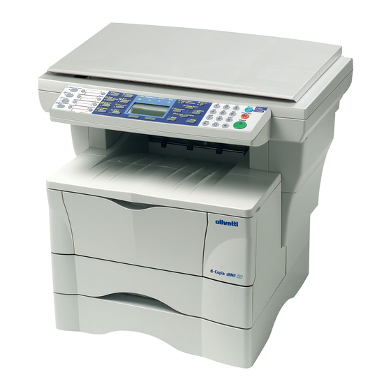
1-1-2 Names of parts (1) Main body ‹ fi fl ⁄ › ‡ ¤ & Figure 1-1-1 Names of parts 1 Original cover % Stopper extension lock 2 Contact glass ^ Face-down output tray 3 Original size indicator plate & MP tray 4 Operation panel * Extension tray 5 Front top cover... -
Page 16: Operation Panel
(2) Operation panel & ⁄ fl ‡ · ¤ ‹ — › fi ‚ Œ „ Figure 1-1-2 1 Status/Job cancel key and indicator & Main power indicator 2 Copy key and indicator * Original quality key and indicator 3 Send key and indicator ( Original size key and indicator 4 One-touch keys (1 to 8) ) Exposure key and indicator... -
Page 17: Drum
1-2-1 Drum Note the following when handling or storing the drum. • When removing the process unit, never expose the drum surface to strong direct light. • Keep the drum at an ambient temperature between 10 °C/50 °F and 32.5 °C/90.5 °F and at a relative humidity not higher than 80% RH. -
Page 19: Installation
1-3-1 Unpacking and installation (1) Installation procedure Start Unpack. Remove the tapes, pads and sheets. Remove the pin holding scanner unit. Install a toner container. Connect the power cord. Inisializing the machine. Load paper. Using the one-touch key sheet. Make test copies. End of installation. - Page 20 Unpack — ‡ · ¤ ⁄ & fi ‹ fl › fi fl Figure 1-3-1 Unpacking 1 Main body ! Front spacer ⁄ Pocket spacer 2 Toner container @ Front pad ¤ Paper tag 3 Power cord # Bottom spacer ‹...
- Page 21 CAUTIONS • Be sure to hold both the front and rear sides of the machine when carrying it, as shown in the illustration. • Be sure not to pull the cassette out when holding the front of the machine. • Be sure that the original cover is closed whenever transporting the machine. •...
- Page 22 Remove the tapes, pads and sheets. 1. Remove the sheet and the two tapes. Tapes Sheet Figure 1-3-3 2. Open the original cover. Original cover Figure 1-3-4 1-3-4 Service Manual Y104230-6...
- Page 23 3. Remove the eight tapes, the two pads and the sheet. Tapes Sheet Tape Tapes Tape Figure 1-3-5 4. Pull the cassette out of the machine. Cassette Figure 1-3-6 Cassette spacer 5. Remove the cassette spacer from inside the cassette. Figure 1-3-7 1-3-5 Y104230-6...
- Page 24 Remove the pin holding scanner unit. 1. Remove the yellow pin for scanner unit and the paper tag from the left side of the machine. Paper tag Figure 1-3-8 Install a toner container. 1. Open the front top cover and front cover. Front top cover Front cover Figure 1-3-9...
- Page 25 3. Remove the process unit from the machine. CAUTIONS • Place the process unit on a clean, level surface. • Never expose the process unit to any sort of impact or shock. • The drum in the process unit is sensitive to light. Never expose the drum even to normal office lighting (500 lux) for more than five minutes.
- Page 26 6. Shake the toner container horizontally back and forth five or six times so that the toner inside of it becomes evenly distributed. Toner container Figure 1-3-14 7. Remove the orange protective seal. Seal Figure 1-3-15 8. Align the knob on the left side of the container with the groove in the process unit and set the toner container into the process unit.
- Page 27 9. Hold the process unit stable and push on the areas marked PUSH HERE on the toner Toner container container until the container clicks into place. Figure 1-3-17 10. Push the lock lever back into its locked position. Lock lever Figure 1-3-18 11.
- Page 28 12. Close the front cover. Front cover Figure 1-3-20 13. Close the front top cover. Front top cover Figure 1-3-21 1-3-10 Service Manual Y104230-6...
- Page 29 Connect the power cord. 1. Connect the power cord. Power cord Figure 1-3-22 Initializing the machine. 1. Turn the power switch to the machine ON ( | ). Power switch Figure 1-3-23 The machine will begin replenishing the toner. Wait until it has completed that operation. (15 minutes) Once the toner has been replenished and the machine is once again in a ready-to-use state,...
- Page 30 Load paper. 1. Pull the cassette out of the machine. Cassette Figure 1-3-25 2. Adjust the paper stopper in the rear portion of the Paper stopper cassette to fit the size of the paper being loaded there by pressing in on the release buttons and sliding the paper stopper to the corresponding paper size.
- Page 31 4) Press down on the stopper extension lock and slide the paper stopper towards the rear of the cassette to set the lock into place. Paper stopper The paper stopper is in position for Folio and Oficio II size paper. Stopper extension lock Figure 1-3-28...
- Page 32 NOTES • Always adjust the paper stopper and paper width guides before loading paper into the cassette. Paper width guide Failure to do so may result in skewed paper feed and/or a paper jam. • Make sure that the paper is set securely against the paper stopper and the paper width guides.
- Page 33 Using the one-touch key sheet. 1. Remove the one-touch key sheet from bottom side of the operation panel. One-touch key sheet Figure 1-3-33 2. Enter the information for the registered destinations onto the one-touch key sheet. (There are 4 spare one-touch key sheets included with this machine.) 3.
-
Page 34: Connecting The Cable
1-3-2 Connecting the cables (1) Connecting the network cable To connect the machine to a network, use an network cable (10Base-T or 100Base-TX). Procedure 1. Turn the power switch located on the rear side of the machine off (O), and remove the power cord from the outlet. -
Page 35: Connecting The Printer Cable
(2) Connecting the printer cable To connect the machine directly to your computer, use either a parallel cable or USB cable. Procedure 1. Turn the power switch located on the rear side of the machine off (O), remove the power cord from the outlet and turn the power off to computer. -
Page 36: Installing The Document Processor (Option)
1-3-3 Installing the document processor (option) Procedure 1. Remove all of the components to the document processor from the box. CAUTION Be sure to hold both sides of the document processor when carrying it, as shown in the illustration. Be particularly careful NOT to touch the guide film or the thin white surface indicated by the A in the illustration. - Page 37 4. Attach the document processor to the machine. CAUTION Be sure that the connection cable does not get caught between the document processor and the machine when attaching the document processor to the machine. Connection cable Figure 1-3-42 5. Gently close the document processor. Document processor Figure 1-3-43...
-
Page 38: Connecting The Cable 1
CAUTION Be sure to tighten the pins securely when connecting the cable. Pins Figure 1-3-45 7.Connect the power cord and turn the power switch on ( | ). Warm up will begin. 1 will appear on the operation panel and the start indicator will light when the machine is in a ready state. -
Page 39: Installing The Expanding Memory (Option)
1-3-4 Installing the expanding memory (option) The main PWB of the machine is equipped with one socket for memory expansion. Expansion memory is available in the form of DIMM (Dual In-line Memory Module). CAUTION Take precautions that no foreign substances such as metal chips or liquid get inside the machine during the installation process. -
Page 40: Installing The Fax System (Option)
1-3-5 Installing the fax system (option) Turn the machine's power switch to OFF and unplug the machine from the power supply before installing the fax system. Precautions for handling the FAX assembly The FAX assembly is delivered in an antistatic air- padded bag. - Page 41 3. Connect the modular cord to the line jack. 120 V specifications: Connect the modular cord with the attached ferrite core to the machine. Line jack Figure 1-3-51 220-240 V specifications only 4. Attach the core to the power cord of the machine so that the stopper section is located near the Core power plug as shown in the illustration.
- Page 42 Initialization procedure after installation of fax system 1. Insert the machine power plug to the wall outlet and turn the power switch on. 2. Run maintenance item U601. 3. Enter a destination code using the numeric keys (refer to the destination code list) and then press the enter key. * Enter a destination code with three digits.
-
Page 43: Maintenance Mode
1-4-1 Maintenance mode The machine is equipped with a maintenance function which can be used to maintain and service the machine. (1) Executing a maintenance item Start Press the system menu/counter key. Select Service setting using the up/down cursor keys. While pressing the start key and the # key, Maintenance mode is entered. -
Page 44: Maintenance Modes
(2) Maintenance modes Item Initial Category Maintenance setting* General U000 Outputting an own-status report — Initialization U020 Initializing all data — Drive, paper U034 Setting paper timing feed and paper • Adjusting the leading edge registration — conveying • Adjusting the center line —... -
Page 45: Contents Of Maintenance Mode Items
(3) Contents of maintenance mode items Maintenance Description item No. U000 Outputting an own-status report Description Outputs lists of the current settings of the maintenance items, and paper jam and service call occurrences and event log report. Purpose To check the current setting of the maintenance items, or paper jam or service call occurrences. Before initializing the backup RAM, output a list of the current settings of the maintenance items to reenter the settings after initialization or replacement. - Page 46 Maintenance Description item No. Item Description 1 Paper Jam Log #: Log number 1 to 16 jams are recorded. (If the number of jams exceeds 16, the oldest log is deleted.) Count.: Number of pages Total page counter at the time of jam Event: Log code Six types of two-digit hexadecimal numbers are displayed.
- Page 47 Maintenance Description item No. Item Description (c) Paper size 01: Envelope Monarch 09: B5 1F: Postcard 02: Envelope #10 0D: A5 20: Reply-paid postcard 03: Envelope DL 0E: A6 21: Officio II 04: Envelope C5 0F: B6 28: 16K 05: Executive 10: Envelope #9 32: Statement 06: Letter...
- Page 48 Maintenance Description item No. U020 Initializing all data Description Initializes all the backup RAM on the engine PWB to return to the original settings. Purpose Used when replacing backup RAM on the engine PWB. After initialization, run U157 “Changing the developing drive time”...
- Page 49 Maintenance Description item No. U063 Adjusting the shading position Description Changes the shading position. Purpose Used when white lines continue to appear longitudinally on the image after the shading plate is cleaned. This is due to flaws or stains inside the shading plate. To prevent this problem, the shading position should be changed so that shading is possible without being affected by the flaws or stains.
- Page 50 Maintenance Description item No. U074 Adjusting the DP input light luminosity Description Adjusts the luminosity of the exposure lamp for scanning originals from the DP. Purpose Used if the exposure amount differs significantly between when scanning an original on the contact glass and when scanning an original from the DP.
- Page 51 Maintenance Description item No. U089 Outputting a MIP-PG pattern Description Selects and outputs a MIP-PG pattern created in the machine. Purpose When performing respective image printing adjustments, used to check the machine status apart from that of the scanner with a non-scanned output MIP-PG pattern. Method 1.
- Page 52 Maintenance Description item No. U089 Method: 1dot PG output 1. Change the setting using the left/right cursor keys. Description Setting range Initial setting Number of 1dot pattern 1 to 16 2. Press the enter key. The value is set. 3. Press the system menu/counter key. The machine enters the PG pattern output mode. 4.
- Page 53 Maintenance Description item No. U144 Setting toner loading operation Description Sets toner loading operation. Purpose To run when drum filming (background blur in paper edge section) occurs. Method Press the enter key. Setting 1. Change the setting using the left/right cursor keys. Setting value Description Toner not loaded...
- Page 54 Maintenance Description item No. U161 Setting the fusing control temperature Description Changes the fusing control temperature. Purpose Normally no change is necessary. However, can be used to prevent curling or creasing of paper, or solve a fusing problem on thick paper. Method Press the enter key.
- Page 55 Maintenance Description item No. U203 Operating DP separately Description Simulates the original conveying operation separately in the DP. Purpose To check the DP. Method 1. Press the enter key. A selection item appears. 2. Select the item to using the up/down cursor keys. Display Operation With paper...
- Page 56 Maintenance Description item No. U403 Adjusting margins for scanning an original on the contact glass Adjustment See page 1-6-48. U404 Adjusting margins for scanning an original from the DP Adjustment See page 1-6-53. U411 Adjusting the scanner automatically Description Uses the original for adjustment to carry out the automatic adjustment of scanner (scanner center line adjustment, scanner leading edge registration adjustment, magnification of the scanner in the auxiliary scanning direction adjustment, monochrome/color input γ...
- Page 57 Maintenance Description item No. U425 Setting the target Description When running U411 “Adjusting the scanner automatically,” input the color data value of the specified patch written in the LAB value table on the back side of the original for adjustment. Note that incorrect value input results in improper automatic adjustment.
- Page 58 Maintenance Description item No. U901 Checking/clearing print counts by paper feed locations Description Displays or clears print counts by paper feed locations. Purpose To check the time to replace consumable parts. Also to clear the counts after replacing the consumable parts. Method 1.
- Page 59 Maintenance Description item No. U927 Clearing accounting counter Description Clears the total count, scanner count and machine life count. The counts, however, can be cleared only one time. If either of the total count, canner count or machine life count exceeds 1,000, this mode cannot be run. Purpose To start the counters with value 0 when installing the machine.
-
Page 60: System Settings
1-4-2 System settings In addition to a maintenance function, the machine is equipped with a system settings which can be operated by users (mainly by the machine administrator). In this machine system settings, default settings can be changed. (1) Executing a system setting item •... -
Page 61: System Settings
(2) System settings Adjusting the contrast of the message display Registering destination E-mail addresses under 1. Select Adjust and press the enter key. one-touch keys 2. Select LCD Contrast and press the enter key. 1. Select Common Setting and press the enter key. 3. - Page 62 Setting of the reset time Setting defalt original size 1. Select Date/Timer Set. and press the enter key. 1. Select Common Setting and press the enter key. 2. Select Reset Timer and press the enter key. 2. Select Orig./Paper Set. and press the enter key. 3.
-
Page 63: Service Settings
1-4-3 Service settings The machine is equipped with a service settings which can be operated by service person. (1) Executing a service setting item ¥ Executing a system setting item Start Press the System Menu/ Counter key. Select Service Setting using the up/down cursor keys. -
Page 64: Contents Of Service Setting Items
(2) Contents of service setting items Service items Description Printing a status page for service purpose Ser. Status Page Description Prints a status page for service purpose. The status page includes various printing settings and service cumulatives. Procedure 1.Select [Ser. Status Page] using up/down cursor keys and press the enter key. 2.Select [Yes] using the left select key. - Page 65 Service items Description Items Description Destination information 1: For Europe/Australia/New Zealand 2: For America/Canada/South America 3: For Europe/Middle East/Asia 17/18/19/21: OEM Area information 1: Europe 2: North America 3: Asia (except Chine) 4: Japan 5: Australia 6: China Printable area Legth/Width Offset for each paper source MP tray top offset/MP tray left offset/Optional drawer...
- Page 66 Service items Description Items Description Maintenance information (Hexadecimal) Data Description Initial setting for the developer Setting toner loading operation Developing drive time (most significant byte) (secod byte) (third byte) (least significant byte) Fusing control temperature: Primary stabilization fusing temperature Secondary stabilization fusing temperature Printing operation temperature 1 Printing operation temperature 2 Number of sheets for fusing control...
- Page 67 Service items Description Items Description Maintenance information (Hexadecimal) Data Description " × 11" size (most significant byte) Paper size counter: 8 (secod byte) (third byte) (least significant byte) " × 8 " size (most significant byte) (secod byte) (third byte) (least significant byte) Other size (most significant byte) (secod byte)
- Page 68 Service items Description Printing a status page for network NW Status Page Description Prints a status page that lists information on the network settings. Procedure 1. Select [NW Status Page] using up/down cursor keys and press the enter key. 2. Select [Yes] using the left select key. Network status pages (3 pages) are output. Sample of network status page NetWare IPX/SPX Logical Printers...
- Page 69 Service items Description Toner installation mode New Developer Description Executes toner install operation when replacing the toner. Procedure 1. Select [New Developer] using up/down cursor keys and press the enter key. 2. Select [Yes] using the left select key. 3. [Completed] is displayed and set the toner install mode. 4.
- Page 70 Service items Description Setting the FAX destination code FAX Country Code Note: This setting is only available when the optional fax system is installed in the machine. Description To set the fax destination code. Basically, the setting need not be changed. Procedure 1.
-
Page 71: Paper Misfeed Detection
1-5-1 Paper misfeed detection (1) Paper misfeed indication When a paper misfeed occurs, the machine immediately stops copying or printing and displays the jam location on the operation panel. To remove paper jammed in the machine, open the face-up output tray, front top cover, front cover or pull the cassette out. To remove original jammed in the optional DP, open the DP original cover. -
Page 72: Paper Misfeed Detection Conditions
(2) Paper misfeed detection conditions Exit Registration sensor sensor Figure 1-5-2 1-5-2 Service Manual Y104230-6... - Page 73 Section Jam code Description Conditions System No paper feed When the power switch is turned on or front top cover is closed, the machine detects activation of the registration sensor or the exit sensor. Cover open JAM A cover open state is detected during copying or printing. Secondary paper feed When the machine waits for secondary paper feed, 15 s or timeout...
-
Page 74: Paper Misfeeds
(3) Paper misfeeds • Main body Problem Causes/check procedures Corrective measures A piece of paper torn from Check visually and remove it, if any. A paper jam in the paper is caught around conveying, fusing or registration sensor or exit exit section is indi- sensor. - Page 75 Problem Causes/check procedures Corrective measures Check if the MP feed roller Check visually and replace any deformed roller. A paper jam in the is deformed. paper feed section Defective registration sen- Check if YC8-7 on the engine PWB remains low when the regis- is indicated during sor.
- Page 76 Problem Causes/check procedures Corrective measures Defective registration sen- Check if YC8-7 on the engine PWB remains low when the regis- A paper jam in the sor. tration sensor is turned on and off. If it does, replace the regis- exit section is indi- tration sensor.
- Page 77 • DP Problem Causes/check procedures Corrective measures A piece of paper torn from Remove any found. An original jams an original is caught when the power around the DP timing switch is turned on. switch. Defective DP timing Check if YC10-6 on the engine PWB remains low when the DP switch.
-
Page 78: Self-Diagnosis
1-5-2 Self-diagnosis (1) Self-diagnostic function This unit is equipped with a self-diagnostic function. When a problem is detected, copying is disabled. C and a number between 0030 and 7990 altenates, indicating the nature of the problem. After removing the problem, the self-diagnostic function can be reset by turning interlock switch off and back on. (2) Self diagnostic codes Remarks Code... - Page 79 Remarks Code Contents Causes Check procedures/corrective measures C0220 Communication problem between Poor contact in Check the connection of connectors YC13 the main PWB and operation PWB the connector ter- on the main PWB and YC3 on the opera- • There is no reply after 20 retries at minals.
- Page 80 Remarks Code Contents Causes Check procedures/corrective measures C2000 Main motor problem Poor contact in Reinsert the connector. Also check for con- • LOCK ALM signal remains high for 1 the main motor tinuity within the connector cable. If none, s, 1 s after the main motor has turned connector termi- remedy or replace the cable.
- Page 81 Remarks Code Contents Causes Check procedures/corrective measures C4000 Polygon motor synchronization Poor contact in Reinsert the connector. Also check for con- problem the polygon motor tinuity within the connector cable. If none, • The polygon motor does not reach connector termi- remedy or replace the cable.
- Page 82 Remarks Code Contents Causes Check procedures/corrective measures C6050 Abnormally low fusing unit ther- Poor contact in Check the connection of connector YC4 on mistor temperature the thermistor the power supply PWB and the continuity • The fusing temperature remains be- connector termi- across the connector terminals.
- Page 83 Remarks Code Contents Causes Check procedures/corrective measures C7980 Waste toner reservoir overflow Defective waste Shake the process unit from side to side problem (when the total number of toner sensor or and turn the power switch off and then on. copies is less than 100 thousand engine PWB.
- Page 84 Remarks Code Contents Causes Check procedures/corrective measures CF5-- Controller system error Defective main If this error occurs again even after the PWB. power switch is turned off and then on again, contact the Service Administrative Division. CF6-- Controller system error Defective main If this error occurs again even after the PWB.
-
Page 85: Image Formation Problems
1-5-3 Image formation problems (1) No image appears (2) No image appears (3) Image is too light. (4) Background is visible. (entirely white). (entirely black). See page 1-5-16 See page 1-5-16 See page 1-5-17 See page 1-5-17 (8) One side of the print (5) A white line appears (7) A black line appears (6) A black line appears... - Page 86 (1) No image appears Causes (entirely white). 1. No transfer charging. Causes Check procedures/corrective measures 1. No transfer charging. A. The connector terminals of the high voltage Reinsert the connector. Also check for continuity within the PWB make poor contact. connector cable.
- Page 87 (3) Image is too Causes light. 1. Insufficient toner. 2. Deteriorated developer. 3. Dirty or deteriorated drum. Causes Check procedures/corrective measures 1. Insufficient toner. If the add toner indicator lights, replace the toner container. 2. Deteriorated developer. Replace the process unit. 3.
- Page 88 (6) A black line appears Causes longitudinally. 1. Dirty contact glass. 2. Dirty or flawed drum. 3. Deformed or worn cleaning blade. 4. Dirty scanner mirror. Causes Check procedures/corrective measures 1. Dirty contact glass. Clean the contact glass. 2. Dirty or flawed drum. Replace the process unit.
- Page 89 (9) Black dots appear Causes on the image. 1. Dirty or flawed drum. 2. Dirty contact glass. 3. Deformed or worn cleaning blade. Causes Check procedures/corrective measures 1. Dirty or flawed drum. Replace the process unit. 2. Dirty contact glass. Clean the contact glass.
- Page 90 (12) Paper creases. Causes 1. Paper curled. 2. Paper damp. Causes Check procedures/corrective measures 1. Paper curled. Check the paper storage conditions. 2. Paper damp. Check the paper storage conditions. (13) Offset occurs. Causes 1. Defective cleaning blade. Causes Check procedures/corrective measures 1.
- Page 91 (15) Fusing is poor. Causes 1. Wrong paper. 2. Flawed press roller. Causes Check procedures/corrective measures 1. Wrong paper. Check if the paper meets specifications. 2. Flawed press roller. Replace the press roller (see page 1-6-26). (16) Image center does not Causes align with the original 1.
-
Page 92: Electrical Problems
1-5-4 Electrical problems Problem Causes Check procedures/corrective measures No electricity at the power Measure the input voltage. The machine does outlet. not operate when The power cord is not Check the contact between the power plug and the outlet. the power switch is plugged in properly. -
Page 93: The Mp Feed Clutch Does Not Operate
Problem Causes Check procedures/corrective measures Broken MP feed clutch Check for continuity across the coil. If none, replace the MP feed The MP feed clutch coil. clutch. does not operate. Poor contact in the MP Reinsert the connector. Also check for continuity within the con- feed clutch connector ter- nector cable. -
Page 94: Main Charging Is Not Performed
Problem Causes Check procedures/corrective measures (13) Broken main charger wire. See page 1-5-16. Main charging is not Leaking main charger performed. housing. Poor contact in the high voltage PWB connector terminals. Defective engine PWB. Defective high voltage PWB. (14) Poor contact in the high See page 1-5-16. -
Page 95: Mechanical Problems
1-5-5 Mechanical problems Problem Causes/check procedures Corrective measures Check if the surfaces of the feed roller and Clean with isopropyl alcohol. No primary paper feed. MP feed roller are dirty with paper powder. Check if the feed roller and MP feed roller Check visually and replace any deformed are deformed. -
Page 97: Precautions For Assembly And Disassembly
1-6-1 Precautions for assembly and disassembly (1) Precautions • Be sure to turn the power switch off and disconnect the power plug before starting disassembly. • When handling PWBs, do not touch connectors with bare hands or damage the board. •... -
Page 98: Removing The Process Unit
1-6-2 Removing the process unit 1. Open the front top cover. 2. Open the front cover. 3. Lift the process unit together with the toner container out of the machine. Front top cover Front cover Process unit Figure 1-6-1 Removing the process unit CAUTIONS •... -
Page 99: Removing The Principal Outer Covers
1-6-3 Removing the principal outer covers (1) Removing the front top cover/face-down output tray 1. Remove the screw and then remove the memory cover. 2. Remove the screw and then remove the rear cover. Screw Rear cover Memory cover Screw Figure 1-6-2 Removing the memory cover and rear cover 3. -
Page 100: Removing The Right Cover
(2) Removing the right cover 1. Remove the front top cover/face-down output tray (see page1-6-3). 2. Remove the memory cover (see page 1-6-3). 3. Unlatch the snaps and hook, remove the right cover. Right cover :Snap/Hook (inside cover) Right cover Figure 1-6-4 Removing the right cover (3) Removing the left cover 1. -
Page 101: Removing The Feed Roller
1-6-4 Removing the feed roller CAUTION When refit the feed roller, fit the D-cut shaft into the D-shape hole of the feed roller. 1. Remove the cassette and the process unit (see page 1-6-2). 2. Stand the machine the front side up. 3. -
Page 102: Removing The Mp Feed Roller
1-6-5 Removing the MP feed roller 1. Remove the engine PWB (see page 1-6-9). 2. Remove the screw. 3. Remove the grounding plate. 4. Remove the stop ring . 5. Remove the MP feed clutch. MP feed clutch Stop ring Grounding plate Screw... - Page 103 6. Remove the screw. 7. Remove the toner sensor and spring. 8. Remove two screws. 9. While pressing the latch by using the driver and then remove the MP feed unit. Toner sensor Screw Screw Spring Screw Latch MP feed unit Figure 1-6-8 Removing the MP feed unit 10.
-
Page 104: Removing The Transfer Roller
1-6-6 Removing the transfer roller CAUTION Do not touch the transfer roller (sponge) surface. Oil and dust (particles of paper, etc.) on the transfer roller can significantly deteriorate the print quality (white spots, etc.). When refitting the bushes and springs, make sure to refit the black colored bush and spring on the left side. Also, observe the correct direction to which the bush is fit in reference to the paper passing direction. -
Page 105: Removing The Primary Circuit Pwbs
1-6-7 Removing the primary circuit PWBs (1) Removing the engine PWB 1. Remove the right cover (see page 1-6-4). 2. Remove all (twelve) connectors from the engine PWB. 3. Remove three screws. 4. Remove the engine PWB. * When replacing the PWB with a new PWB, remove the EEPROM from the old PWB and mount it to the new PWB. -
Page 106: Removing The Main Pwb
(2) Removing the main PWB 1. Remove the right cover (see page 1-6-4). 2. Remove the connector. 3. Remove the screw and then remove the speaker. Connector Speaker Screw Figure 1-6-12 Removing the speaker 4. Remove three connectors. 5. Remove the flexible flat cable. 6. - Page 107 7. Remove two screws at the back of the main PWB. * When replacing the PWB with a new PWB, remove the EEPROM from the old PWB and mount it to the new PWB. Main PWB Screws EEPROM Figure 1-6-14 Removing the main PWB 1-6-11 Y104230-6 Sevice Manual...
-
Page 108: Removing The Power Supply Pwb And High Voltage Pwb
(3) Removing the power supply PWB and high voltage PWB 1. Remove the process unit (see page 1-6-2). 2. Remove the left cover (see page 1-6-4). 3. Remove three connectors from the power supply PWB. 4. Remove eight screws. 5. Remove the power supply PWB and high voltage PWB. (Note: The high voltage PWB is directly connected to the bias PWB.) 6. -
Page 109: Removing The Bias Pwb
(4) Removing the bias PWB 1. Remove the cassette and process unit (see page 1-6-2). 2. Remove the left cover (see page 1-6-4). 3. Remove the power supply PWB and high voltage PWB (see page 1-6-12). 4. Stand the machine with the front side up. 5. -
Page 110: Removing The Main Motor And Drive Unit
1-6-8 Removing the main motor and drive unit 1. Remove the cassette and process unit (see page 1-6-2). 2. Remove the right cover (see page 1-6-4). 3. Remove three connectors from the main motor. 4. Remove four screws. 5. Remove main motor. Connectors Main motor Screws... - Page 111 6. Remove the engine PWB (see page 1-6-9). 7. Remove wires from wire saddles on the cord cover. 8. Remove the screw. 9. Remove the cord cover. Wire saddle Screw Wire saddles Cord cover Figure 1-6-18 Removing the cord cover 1-6-15 Y104230-6 Sevice Manual...
- Page 112 10. Remove the main PWB (see page 1-6-10). 11. Remove the screw and then remove the grounding plate. 12. Remove the screw and then remove the feed clutch. 13. Remove three stop rings. 14. Remove MP feed clutch (gear), feed clutch (gear), and registration clutch (gear). MP feed clutch (gear) Grounding Stop ring...
- Page 113 15. Remove four screws. 16. Remove the drive unit. Drive unit Screws Figure 1-6-20 Removing the drive unit 1-6-17 Y104230-6 Sevice Manual...
-
Page 114: Removing And Splitting The Fuser Unit
1-6-9 Removing and splitting the fuser unit WARNING • The fuser unit is hot after the machine was running. Wait until it cools down. CAUTION • When refitting the fuser unit, make sure the fuser unit gear and the machine’s drive gear are properly meshed with each other. - Page 115 6. Remove two screws. 7. Open and split the fuser unit. Screw Fuser unit Screw Figure 1-6-22 Splitting the fuser unit 1-6-19 Y104230-6 Sevice Manual...
-
Page 116: Removing The Separation Craws
(1) Removing the separation claws WARNING The separation claws are extremely hot immediately after the copier was running. Allow substantial period of time until it cools down. 1. Remove and split the fuser unit (see page 1-6-18). 2. Loosen the stopper screws. 3. -
Page 117: Removing The Heater Lamp
(2) Removing the heater lamp WARNING • The heater lamp is extremely hot immediately after the machine was running. • Allow substantial period of time until it cools down. Also, the heater lamp is fragile: Handle it with great care. CAUTION •... -
Page 118: Removing The Heat Roller
(3) Removing the heat roller WARNING • The heat roller is extremely hot immediately after the machine was running. Allow substantial period of time until it cools down. 1. Remove and split the fuser unit (see page 1-6-18). 2. Remove the heater lamp (see page 1-6-22). 3. - Page 119 4. Remove the heat gear Z33, heat R bush, and heat L bush from the heat roller. Heat gear Z33 Heat R bush Heat L bush Heat roller Figure 1-6-26 Removing the heat roller 1-6-23 Y104230-6 Sevice Manual...
-
Page 120: Removing The Thermistor
(4) Removing the thermistor 1. Remove and split the fuser unit (see page 1-6-18). 2. Remove the heater lamp (see page 1-6-21). 3. Remove the heat roller (see page 1-6-22). 4. Remove the screw. 5. Remove the thermistor. Screw Thermistor Figure 1-6-27 Removing the thermistor 1-6-24 Service Manual... -
Page 121: Removing The Thermal Cutout
(5) Removing the thermal cutout CAUTION • Do not bend the terminals of the thermal cutout. 1. Remove and split the fuser unit (see page 1-6-18). 2. Remove the heater lamp (see page 1-6-21). 3. Remove the heat roller (see page 1-6-22). 4. -
Page 122: Removing The Press Roller
(6) Removing the press roller WARNING • The press roller is extremely hot immediately after the machine was running. Allow substantial period of time until it cools down. 1. Remove and split the fuser unit (see page 1-6-18). 2. Remove the press roller from the fuser unit. Press roller Fuser unit Figure 1-6-29 Removing the press roller... -
Page 123: Removing And Scanner Unit
1-6-10 Removing the scanner unit 1. Remove the right and left cover (see page 1- 6-4). 2. Remove the speaker (see page 1-6-10). 3. Remove five connectors and two flexible flat cables from the scanner PWB. 4. Remove five screws and then remove the Screw scanner PWB. - Page 124 4. Remove two screws. 5. Slide the scanner unit and then remove the scanner unit. Scanner unit Screws Figure 1-6-31 Removing the scanner unit 1-6-28 Service Manual Y104230-6...
-
Page 125: Removing The Laser Scanner Unit And The Eraser Lamp
1-6-11 Removing the laser scanner unit and the eraser lamp 1. Remove the scanner unit (see page 1-6-27). 2. Remove two screws and then remove grounding plate. 3. Remove each two screws and then remove the right and left scanner stays. Screws Screws Left scanner stay... - Page 126 6. Remove three screws. 7. Remove two connectors from the laser scanner unit. 8. Remove the laser scanner unit. * When refitting the laser scanner unit, tighten a screw in order of 3 from 1. Screws Laser scanner unit Conncetor Conncetor Figure 1-6-34 Removing the laser scanner unit 1-6-30...
- Page 127 9. Remove the eraser lamp. Eraser lamp Figure 1-6-35 Removing the eraser lamp 1-6-31 Y104230-6 Sevice Manual...
-
Page 128: Removing The Isu Unit
1-6-12 Removing the ISU unit 1. Unhook two hooks by using screw driver through the holes and then remove the operation unit. Hole Operation unit Hook Hook Hole Figure 1-6-36 Removing the operation unit 2. Remove two screws and then remove the original holder cover. - Page 129 3. Remove two screws and then remove two grounding plates. 4. Remove the stopper ring and then detach the scanner shaft. * Detach the shaft taking care to tilt it as little as possible. Stopper ring Screw Grounding plates Scanner shaft Screw Figure 1-6-38 Detaching the scanner shaft 5.
-
Page 130: Removing The Exposure Lamp
1-6-13 Removing the exposure lamp 1. Remove the ISU unit (see page 1-6-32). 2. Remove two connectors from the inverter PWB. 3. Remove the screw and then remove the inverter PWB. ISU unit Inverter PWB Screw Connectors Figure 1-6-40 Removing the inverter PWB 4. - Page 131 5. Remove the exposure lamp and cables from the exposure lamp mount. • Do not touch the glass surfaces of the exposure lamp with bare hands. Exposure lamp Exposure lamp mount Cables Figure 1-6-42 Removing the exposure lamp 1-6-35 Y104230-6 Sevice Manual...
-
Page 132: Removing The Scanner Mirror A
1-6-14 Removing the scanner mirror A 1. Remove the ISU unit (see page 1-6-32). 2. Remove the exposure lamp (see page 1-6- 34). 3. Unhook two mirror A holders and then Mirror A holder remove the scanner mirror A. Scanner mirror A Hook Mirror A holder Scanner mirror A... -
Page 133: Removing The Scanner Motor
1-6-15 Removing the scanner motor 1. Remove the original holder cover (see page 1-6-32). 2. Remove the right cover (see page 1-6-4). 3. Remove the speaker (see page 1-6-10). 4. Remove the connector from the scanner PWB. Scanner PWB Connector Figure 1-6-44 Removing the scanner motor (1) Screw 5. - Page 134 8. Remove three screws and then remove the grounding plate. Screws Grounding plate Screw Figure 1-6-47 Removing the scanner motor (4) 9. Remove the stopper ring and then detach the scanner shaft. Stopper ring * Detach the shaft taking care to tilt it as little as possible.
- Page 135 10.Remove the cable from the cable clamps. 11. Remove four screws and then remove the scanner motor mount with scanner motor. Screws Screw Scanner motor mount Cable Cable clamps Figure 1-6-49 Removing the scanner motor (6) 12. Remove the screw and then remove the scanner motor.
-
Page 136: Removing The Main Charger Unit
1-6-16 Removing the main charger unit 1. Remove the process unit from the machine (see page 1-6-2). 2. Unlatch three snaps, and remove the main charger cap. 3. Draw the main charger unit in the direction of arrow A, then pull it out in the direction of arrow B. Main charger unit Snap... -
Page 137: Adjustment The Maintenance Mode
1-6-17 Adjustment the maintenance mode (1) Adjusting the leading edge registration of image printing Make the following adjustment if there is a regular error between the leading edges of the copy image and original. U066 U071 U034 (P. 1-6-46) (P. 1-6-50) Caution: Check the copy image after the adjustment. -
Page 138: Adjusting The Center Line Of Image Printing
(2) Adjusting the center line of image printing Make the following adjustment if there is a regular error between the center lines of the copy image and original when paper is fed from the cassette. U067 U072 U034 (P. 1-6-47) (P. -
Page 139: Adjusting The Amount Of Slack In The Paper
(3) Adjusting the amount of slack in the paper Make the following adjustment if the leading edge of the copy image is missing or varies randomly, or if the copy paper is Z-folded. Procedure Start Enter maintenance mode. Enter 051 using Correct image Copy Copy... -
Page 140: Adjusting Magnification Of The Scanner In The Main Scanning Direction
(4) Adjusting magnification of the scanner in the main scanning direction Perform the following adjustment if the magnification in the main scanning direction is not correct. U065 U065 U067 (auxiliary scanning (main scanning (P. 1-6-47) direction) (P. 1-6-45) direction) Caution: Before making the following adjustment, ensure that the above adjustments have been made in maintenance mode. -
Page 141: Adjusting Magnification Of The Scanner In The Auxiliary Scanning Direction
(5) Adjusting magnification of the scanner in the auxiliary scanning direction Perform the following adjustment if the magnification in the auxiliary scanning direction is not correct. U065 U065 U070 (main scanning (auxiliary scanning (P. 1-6-49) direction) (P. 1-6-44) direction) Caution: Before making the following adjustment, ensure that the above adjustments have been made in maintenance mode. -
Page 142: Adjusting The Scanner Leading Edge Registration
(6) Adjusting the scanner leading edge registration Perform the following adjustment if there is regular error between the leading edges of the copy image and original. U034 U071 U066 (P. 1-6-41) (P. 1-6-50) Caution: Before making the following adjustment, ensure that the above adjustments have been made in maintenance mode. Procedure Leading edge registration Start... -
Page 143: Adjusting The Scanner Center Line
(7) Adjusting the scanner center line Perform the following adjustment if there is a regular error between the center lines of the copy image and original. U034 U072 U067 (P. 1-6-42) (P. 1-6-52) Caution: Before making the following adjustment, ensure that the above adjustments have been made in maintenance mode. Procedure Scanner center line Start... -
Page 144: Adjusting The Margins For Scanning An Original On The Contact Glass
(8) Adjusting the margins for scanning an original on the contact glass Perform the following adjustment if the margins are not correct. U404 U403 (P. 1-6-53) Caution: Check the copy image after the adjustment. If the image is still incorrect, perform the above adjustments in maintenance mode. -
Page 145: Adjusting The Dp Magnification
(9) Adjusting the DP magnification Adjust magnification in the auxiliary scanning direction if magnification is incorrect when the DP is used. U065 U070 (P. 1-6-44) Caution: Before making the following adjustment, ensure that the above adjustments have been made in maintenance mode. Procedure Start Enter maintenance mode. -
Page 146: Adjusting The Dp Leading Edge Registration
(10) Adjusting the DP leading edge registration Perform the following adjustment if there is a regular error between the leading edge of the original and the copy image. U034 U066 U071 (P. 1-6-41) (P. 1-6-46) Caution: Before making the following adjustment, ensure that the above adjustments have been made in maintenance mode. Procedure Leading edge registration Start... -
Page 147: Adjusting The Dp Trailing Edge Registration
(11) Adjusting the DP trailing edge registration Perform the following adjustment if the original scanning end position is not correct when the DP is used. Caution: If the copy image looks like copy example 2, clean the DP original scanning section. Procedure Start Enter maintenance mode. -
Page 148: Adjusting The Dp Center Line
(12) Adjusting the DP center line Perform the following adjustment if there is a regular error between the centers of the original and the copy image. U034 U067 U072 (P. 1-6-42) (P. 1-6-47) Caution: Before making the following adjustment, ensure that the above adjustments have been made in maintenance mode. Procedure Reference Start... -
Page 149: Adjusting The Margins For Scanning The Original From The Dp
(13) Adjusting the margins for scanning the original from the DP Perform the following adjustment if margins are not correct. U403 U404 (P. 1-6-48) Caution: Before making the following adjustment, ensure that the above adjustments have been made in maintenance mode. Procedure (3 ±... -
Page 151: Upgrading The Firmware On The Main Pwb
1-7-1 Upgrading the firmware on the main PWB • When using Compact Flash Firmware upgrading requires the following tools: Compact Flash (Products manufactured by SANDISK are recommended.) NOTE • When writing data from a computer to a new Compact Flash, be sure to format it from the computer in advance. •... - Page 152 • When replacing DIMM Firmware upgrading requires the following tools: DIMM Procedure DIMM slot 1. Turn the power switch off and disconnect the power plug. 2. Remove the pin and then remove the memory cover. 3. Remove the DIMM from the DIMM slot on the main PWB.
-
Page 153: Paper Feeding System
2-1-1 Paper feeding system The paper feeding system picks up paper from the cassette, MP tray, or if installed, the optional cassette, feeds it in the machine, and delivers in the output tray. Paper is fed at the precise timing in synchronization with data processing. The paper feeding system finally delivers the printed page to either the face-down or face-up tray as manipulated by the user. -
Page 154: Paper Feed Control
(1) Paper feed control The following diagram shows interconnectivity of the feeding system components including the sensors and rollers. The engine PWB provides the signals in conjunction with the electrophotography process that is driven by the main PWB. Power train Toner container Process unit Registration... -
Page 155: Paper Feeding Mechanism
(2) Paper feeding mechanism Driving power train A For process unit; drum (From main unit) B For process unit; toner container, developing roller etc. (From main unit) C From process unit; drum (To transfer roller) & fl 1 Main motor (gear) fi... -
Page 156: Original Scanning System
2-1-2 Original scanning system The scanner unit consists of the image scanning unit (ISU) for main-direction scanning, and drive part for traveling the ISU unit to sub-direction. ^ & ⁄ ¤ › ) ‹ Figure 2-1-4 Scanner unit 1 Original holder # Scanner gear 39/22 2 Scanner upper frame $ Scanner shaft... - Page 157 Original Scanner unit ISU unit Scanner Exposure Main PWB lamp image YC6-2 YC1-4 sensor YC6-3 YC1-5 CCDCLKN YC6-4 YC1-14 Inverter CCDCLK YC6-6 YC1-12 CCD PWB YC6-8 YC1-10 YC6-10 YC1-8 LAMP YC2-2 YC6-12 YC1-6 CCDG(O) YC6-16 YC1-18 CCDB(E) YC6-18 YC1-20 CCDR YC6-20 YC1-22 Engine PWB...
-
Page 158: Isu Unit
(1) ISU unit The ISU unit consists of an exposure lamp, three mirrors, an ISU lens, a CCD PWB, and so on. Also an inverter PWB for driving the exposure lamp and a scanner home position sensor for detecting the home position of the ISU unit are incorporated. -
Page 159: Electrophotographic System
2-1-3 Electrophotographic system Electrophotography is the technology used in laser printing which transfer data representing texts or graphics objects into a visible image which is developed on the photosensitive drum, finally fusing on paper, using light beam generated by a laser diode. This section provides technical details on the machine’s electrophotography system. -
Page 160: Process Unit Mechanism
(1-1) Process unit mechanism Driving power train A For drum (From main unit) B For toner container, developing roller, etc. (From main unit) C For main unit (Transfer roller) D For toner container ¤ & ⁄ ‹ Figure 2-1-8 Process unit mechanism 1 Main charger unit # DLP screw B 2 Charger wire... -
Page 161: Main Charging
(2) Main charging (2-1) Photo conductive drum The durable layer of organic photoconductor (OPC) is coated over the aluminum cylinder base. The OPC tend to reduce its own electrical conductance when exposed to light. After a cyclic process of charging, exposure, and development, the electrostatic image is constituted over the OPC layer. -
Page 162: Charging The Drum
(2-2) Charging the drum The following shows a simplified diagram of the electrophotographic components in relation to the engine system. Charging the drum is done by the main charger unit. High voltage PWB Engine PWB Bias MHVDR1 YC1-A4 YC8-10 YC-M MHVDR2 YC1-A9 YC7-8... -
Page 163: Exposure
(3) Exposure The charged surface of the drum is then scanned by the laser beam from the laser scanner unit. Laser scanner unit Drum Figure 2-1-11 Exposure The laser beam (780 nm wavelength) beam is dispersed as the polygon motor (polygon mirrors) revolves to reflect the laser beam over the drum. -
Page 164: Laser Scanner Unit
(3-1) Laser scanner unit Diversion mirror Figure 2-1-12 Laser scanner unit 1 Laser diode ........... Emits diffused, visible laser. 2 Cylindrical lens ..........Compensates the vertical angle at which the laser beam hits a polygon mirror segment. 3 Polygon mirror (motor) ........Has six mirror segments around its hexagonal circumference; each mirror corresponding to one scanned line width on the drum when laser beam scans on it. -
Page 165: Drum Surface Potential
(3-2) Drum surface potential The laser beam is continually switched on and off depending on the print data. It is on for a black (exposed) dot and off for a white (blank) dot. Since the drum surface is evenly charged, whenever it is illuminated by the laser beam, the electrical resistance of the photoconductor is reduced and the potential on the photoconductor is also lowered. -
Page 166: Development
(4) Development The latent image constituted on the drum is developed into a visible image. The developing roller contains a 3-pole (S-N- S) magnet core and an aluminum cylinder rotating around the magnet core. Toner attracts to the developing roller since it is powdery ink made of black resin bound to iron particles. -
Page 167: Transfer
(5) Transfer The image developed by toner on the drum is transferred onto the paper because of the electrical attraction between the toner itself and the transfer roller. The transfer roller is negatively biased so that the positively charged toner is attracted onto the paper while it is pinched by the drum and the transfer roller. -
Page 168: Fusing
(6) Fusing The toner on the paper is molten and pressed into the paper as it passes between the heat roller and the press roller in the fuser unit. Heat roller Press roller Figure 2-1-16 Fusing The heat roller has a halogen lamp inside which continuously turns on and off by the thermistor to maintain the constant temperature onto the heat roller surface. -
Page 169: Fuser Unit Mechanism
(6-1) Fuser unit mechanism Figure 2-1-17 Fuser unit mechanism 7 Heater lamp 1 Heat roller 2 Idle gear Z34 8 Thermal cutout 3 Exit gear Z23 9 Separator(s) 4 Idle gear Z18 0 Thermistor 5 Heat gear Z33 ! Exit pulley(s) @ Lower exit roller 6 Press roller 2-1-17... -
Page 170: Cleaning
(7) Cleaning After the transferring process, the drum needs to be physically cleaned of toner which is residual after the development process. The cleaning blade is constantly pressed against the drum and scrapes the residual toner off to the sweep roller. -
Page 171: Electrical Parts Layout
2-2-1 Electrical parts layout (1) Main unit D 4 % & Figure 2-2-1 Main unit 1 Main PWB 7 Cooling fan 2 Engine PWB 8 Registration clutch 3 Power supply PWB 9 Feed clutch A Power switch 0 MP feed clutch B Exit sensor ! MP paper sensor C AC Inlet... -
Page 172: Scanner Unit
(2) Scanner unit Figure 2-2-2 Scanner unit 1 Operation PWB 2 CCD PWB 3 Scanner PWB 4 Inverter PWB 5 Scanner home position sensor 6 Scanner motor 7 Exposure lamp 2-2-2 Service Manual Y104230-6... -
Page 173: Main Pwb
2-3-1 Main PWB SDA [12:0] CPUA [31:0] SDRAM SDD [31:0] CPUD [31:0] (U14,15) Latch (U1) (U5,7,9) SDA [12:0] SDRAM DIMM SDD [31:0] slot Transceiver (YS2) (U4,6,8,10) ASIC CCDRD,CCDBED,CCDGOD, (U2) CCDSH,CCDCLP,CCDRS, Scanner I/F CCDCLK,CCDSW[1:0] (YC6) LA [22:5] VDFONSPL,OUTPEN. ROMA[4:2], Laser CODE VDATA,BDN ROMOEN[0], scanner unit... - Page 174 YC10 Figure 2-3-2 Main PWB silk-screen diagram 2-3-2 Service Manual Y104230-6...
- Page 175 Connector Pin No. Signal Description Not used Not used Connected AUDIO AUDIO signal to the FAX +3.3 V 3.3 V DC power supply control Ground Address bus A13 Address bus A11 Address bus A9 Ground Address bus A6 Address bus A4 Address bus A2 Ground OP2IFn...
- Page 176 Connector Pin No. Signal Description Ground Data bus D3 Connected Data bus D4 to the Data bus D5 compact Data bus D6 flash socket Data bus D7 CE1n CE1 signal Address bus A10 OE signal Address bus A9 Address bus A8 Address bus A7 3.3 V DC power supply Address bus A6...
- Page 177 Connector Pin No. Signal Description Paper empty signal Select signal Connected CAN signal to the Not used parallel I/F Ground Ground INIT 5 V DC power supply Ground Ground Ground Ground Ground Ground Ground Ground Ground Ground Ground ARARM Ground ASFON Not used FAULT...
- Page 178 Connector Pin No. Signal Description Ground CCDR Image data R (red) signal (analog) Connected to the scanner SGND Ground SGND Ground Connected +3.3 V 3.3 V DC power supply to the +3.3 V 3.3 V DC power supply engine +5 V 5 V DC power supply OUTPEN OUTPEN signal...
-
Page 179: Engine Pwb
2-3-2 Engine PWB Scanner Engine PWB motor ISUMOTA, ISUMOTNA Scanner ISUMOTB, ISUMMOTONB Optional LAMP , LAMPHI, LAMPLOW Main PWB RSTIN HPSWN PLGCLK Scanner home +24V3 position Reset IC RSTN sensor Inverter Exposure PLGDRN lamp PFMDRN PLGRDYN PFSEN, PFPFPER, PFCLK MOTORN Laser scanner unit MRDYN Cassette... - Page 180 YC15 YC11 YC10 YC13 YC14 YC12 Figure 2-3-4 Engine PWB silk-screen diagram 2-3-8 Service Manual Y104230-6...
-
Page 181: Eraser Lamp Control Circuit
(1) Eraser lamp control circuit The CPU (U1) turns pin #86 (ERASER) of U1 to H level, transistors (Q18) turns on consequently, and the 24 V DC given at pin #1 of connector YC14 applies to the eraser lamps. The eraser lamps thus illuminate as the current flows through the eraser lamp, the pin #2 of connector YC14, resistors (R109, R110, and R111), transistor Q18 and the ground. -
Page 182: Heater Lamp Control Circuit
(2) Heater lamp control circuit Activation of the heater lamp is dominated by the HEAT signal which is derived by the engine CPU (U1) at its pin #74. When its level is high, transistor Q8 turns on, photo-triac PC2 and triac TRC1 turn on simultaneously, and the heater lamp is applied with the primary AC voltage in turn. - Page 183 The AC power for the heater is applied in one of the five variations of the zero cross switchings as shown in Figure 2-3-7. Each variation is constituted with the unit of ten positive and negative envelops in five cycles, as obtained by varying the duration during which TRC1 turns on.
- Page 184 Heater lamp turn-on pattern in 1 cycle (10 half waves) AC wave Variation No.1 (Duty 100 %) Zero − cross point Conductivity staus of Triac (TRC1) Variation No.2 (Duty 80 %) − Variation No.3 (Duty 60 %) − Variation No.4 (Duty 40 %) −...
-
Page 185: Polygon Motor Control Circuit
(3) Polygon motor control circuit The main controller PWB supplies the 2598.4 Hz clock pulse (PLGCLK) via the engine PWB to the PLL control IC (IC1) for the polygon motor. To begin printing, the engine CPU U1 turns PLGDR to H level, the PLL control IC (IC1) starts to revolve the polygon motor so that the revolution is 25,984 rpm which depends on the PLGCLK clock pulse. - Page 186 Connector Pin No. Signal Description SGND Ground OVSYNK OVSYNK signal Connected SGND Ground to the main RSTN RSTN signal SGND Ground EGRN EGRN signal SDIR SDIR signal SBSY SBSY signal PDMASKN PDMASKN signal EGSI EGSI signal SCKN SCKN signal EGSO EGSO signal PLGCLK PLGCLK signal...
- Page 187 Connector Pin No. Signal Description +24 V3 24 V DC power supply +24 V3 24 V DC power supply Connected PGND Ground to the bias PGND Ground PAPERN Paper sensor: On/Off SWIN Cassette switch: On/Off RESIT Registration sensor: On/Off TONEREPY Toner sensor: On/Off +24 V2 24 V DC power supply...
- Page 188 Connector Pin No. Signal Description YC14 ERASPW 24 V DC power supply ERASERN Eraser lamp: On/Off Connected PGND Ground to the eraser lamp 2-3-16 Service Manual Y104230-6...
-
Page 189: Power Supply Pwb
2-3-3 Power supply PWB The power supply PWB provides the AC power input and DC power and outputs. The high voltage bias generator circuit is mounted on a separate PWB. A simplified schematic diagram is shown below. Power supply unit Power Current switch... - Page 190 • 100 V Q121 C103 Q122 C104 TRA1 NTC1 C101 C102 • 200 V Q121 C103 Q122 C104 TRA1 NTC1 C101 C102 Figure 2-3-10 Power supply PWB silk-screen diagram 2-3-18 Service Manual Y104230-6...
-
Page 191: Bias Pwb
2-3-4 Bias PWB The bias PWB contains the developing bias output circuit, registration sensor, paper empty sensor, and the cassette switch. It also provides a liaison connection to the high voltage PWB, power supply, and the toner sensor. Bias PWB Engine PWB Toner TONEREPY... -
Page 192: High Voltage Pwb
2-3-5 High voltage PWB The high voltage PWB contains the high voltage output circuit, interlock switch circuit as well as providing a liaison connection with the power supply PWB, bias PWB, and the engine PWB. High voltage PWB High voltage output circuit Engine PWB Main Bias PWB... -
Page 193: Interlock Switch
(1) Interlock switch The interlock switch is located on the high voltage PWB and opened and closed in conjunction with the front cover or the front top cover via the interlock lever. This switch connects and disconnects the +24 V DC power supply line. If the front cover or the front top cover is open, the interlock switch is open, and the +24 V DC to the high voltage output circuit, bias PWB, engine PWB, and the power supply PWB is disconnected, deactivating the high voltage output, laser output, main motor output for safety. - Page 194 2-3-6 CCD PWB The CCD PWB consists mainly of a CCD sensor (U4) that scans an original. The CCD sensor (U4) is driven to scan an original by the CCD sensor control signals (CCDCLKN, SH_BW, SH_RGB, SW, SWN, CPN, and RSN) based on the clock for driving the CCD sensor (CCDCLK) supplied from the main PWB through the scanner PWB.
- Page 195 Figure 2-3-17 CCD PWB silk-screen diagram Connector Pin No. Signal Description Ground Ground Connected Ground to the Color/monochro control signal scanner Color/monochro control signal CCD shift signal Ground CCD CP signal Ground CCD RS signal Ground CCDCLK CCD clock signal Ground CCDCLKN CCD clock signal...
-
Page 196: Operation Pwb
2-3-7 Operation PWB The operation PWB consists of key switches and LEDs. The lighting of LEDs is determined by scan signals (SCAN0 to SCAN7) and LED lighting selection signals (LED0 to LED3) from the main PWB. The key switches operated are identified by the scan signals (SCAN0 to SCAN7) and the return signals (KEYIN0 to KEYIN7). - Page 197 Figure 2-3-19 Operator PWB silk-screen diagram Connector Pin No. Signal Description SGND Ground AUDIO AUDIO signal Connected +5 V 5 V DC power supply to the main FPRST FPRST signal PANTXD PANTXD signal PANRXD PANRXD signal PANRTS PANRTS signal PANCTS PANCTS signal +3.3 V 3.3 V DC power supply...
-
Page 198: Scanner Pwb
2-3-8 Scanner PWB The scanner PWB consists of scanner driver circuit Q1 to Q5 and exposure lamp driver circuit U1, relays signals from engine PWB, main PWB, operation PWB, CCD PWB and optional document processor. Scanner PWB ISUMOTA MOTA Driver MOTNA ISUMOTNA Scanner... - Page 199 2-4-1 Y104230-6 Sevice Manual...
- Page 200 2-4-2 Service Manual Y104230-6...
- Page 201 2-4-3 Y104230-6 Sevice Manual...
- Page 202 Wiring diagram NC/NC A1/B1 A1/B1 NC/TXDREQ A2/B2 A2/B2 AUDIO/Power 3.3V A3/B3 A3/B3 Power 3.3V/A15 A4/B4 A4/B4 GND/A14 A5/B5 A5/B5 A13/A12 A6/B6 A6/B6 A11/A10 A7/B7 A7/B7 A9/A8 A8/B8 A8/B8 Optional fax GND/A7 A9/B9 A9/B9 A6/A5 A10/B10 A10/B10 A4/A3 A11/B11 A11/B11 To optional document processor FCPWB A2/A1 A12/B12...
- Page 203 UPDATING STATUS DATE UPDATED PAGES PAGES CODE 09/2005 EDITION Y104230-6...
Need help?
Do you have a question about the d-Copia 18MF and is the answer not in the manual?
Questions and answers