Table of Contents
Advertisement
Quick Links
One Technology Way • P.O. Box 9106 • Norwood, MA 02062-9106, U.S.A. • Tel: 781.329.4700 • Fax: 781.461.3113 • www.analog.com
Evaluation Board for the
24-Bit, Sigma-Delta ADC with In-Amp and Reference
FEATURES
Full featured evaluation board for the
PC control in conjunction with the Analog Devices, Inc.,
System Demonstration Platform (EVAL-SDP-CB1Z)
PC software for control and data analysis (time domain)
Standalone capability
EVALUATION KIT CONTENTS
EVAL-AD7124-4SDZ
evaluation board
Evaluation software CD for the
ONLINE RESOURCES
Documents Needed
AD7124-4
data sheet
EVAL-AD7124-4SDZ
user guide
Required Software
AD7124-4 EVAL+ Software
EQUIPMENT NEEDED
EVAL-AD7124-4SDZ
evaluation board
EVAL-SDP-CB1Z
System Demonstration Platform
DC signal source
USB cable
PC running Windows with USB 2.0 port
PLEASE SEE THE LAST PAGE FOR AN IMPORTANT
WARNING AND LEGAL TERMS AND CONDITIONS.
AD7124-4
AD7124-4
AD7124-4
EVAL-AD7124-4SDZ User Guide
4-Channel, Low Noise, Low Power,
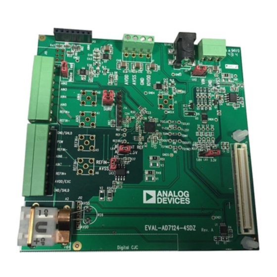
GENERAL DESCRIPTION
The
EVAL-AD7124-4SDZ
24-bit, low power, low noise analog-to-digital converter (ADC).
A 7 V to 9 V external supply is regulated to 3.3 V to supply the
AD7124-4
and to support all necessary components. The
EVAL-AD7124-4SDZ
PC via the connection to the
The
AD7124-4 EVAL+ Software
device register functionality and provides dc time domain
analysis in the form of waveform graphs, histograms, and
associated noise analysis for ADC performance evaluation.
The
EVAL-AD7124-4SDZ
user to evaluate the features of the ADC. The user PC software
executable controls the
EVAL-SDP-CB1Z
board.
Full specifications on the
data sheet, which should be consulted in conjunction with this
user guide when working with the evaluation board.
Rev. 0 | Page 1 of 29
evaluation kit features the
board connects to the USB port of the
EVAL-SDP-CB1Z
fully configures the
is an evaluation board that allows the
AD7124-4
over the USB through the
System Demonstration Platform (SDP)
AD7124-4
are available in the product
UG-855
AD7124-4
motherboard.
AD7124-4
Advertisement
Table of Contents

Related Manuals for Analog Devices EVAL-AD7124-4SDZ


Summary of Contents for Analog Devices EVAL-AD7124-4SDZ
-
Page 1: Features
AD7124-4 Full featured evaluation board for the AD7124-4 PC control in conjunction with the Analog Devices, Inc., 24-bit, low power, low noise analog-to-digital converter (ADC). System Demonstration Platform (EVAL-SDP-CB1Z) A 7 V to 9 V external supply is regulated to 3.3 V to supply the... -
Page 2: Table Of Contents
Revision History ................2 Software Operation ..............12 EVAL-AD7124-4SDZ Block Diagram ........... 3 Configuration Tab ..............12 EVAL-AD7124-4SDZ Quick Start Guide ........4 Wavefrom Tab ................14 Evaluation Board Hardware ............5 Histogram Tab ................16 Device Description ............... 5 Register Map Tab ................ -
Page 3: Eval-Ad7124-4Sdz Block Diagram
EVAL-AD7124-4SDZ User Guide UG-855 EVAL-AD7124-4SDZ BLOCK DIAGRAM ADP1720ARMZ-R7 27kΩ 1.8V OUTPUT ADP1720 ADR4525 57.6kΩ 3.3V OUTPUT 2.5V OUTPUT 7V TO 9V VOUT REGCAPA REFOUT REFIN1(+) REFIN1(–) REGCAPD BANDGAP REFIN2(+) BIAS 1.9V 1.8V REFIN2(–) CROSSPOINT ON-BOARD NOISE TEST AIN0 TO AIN1... -
Page 4: Eval-Ad7124-4Sdz Quick Start Guide
PC using the (the software is included on the CD in the evaluation kit, supplied USB cable. If you are using Windows® XP, you or it can be downloaded from the Analog Devices website). may need to search for the EVAL-SDP-CB1Z drivers. -
Page 5: Evaluation Board Hardware
Full details end for high precision measurement applications. It contains a about the EVAL-SDP-CB1Z are available on the Analog Devices low noise, 24-bit, Σ-Δ ADC. It can be configured to have four website. differential inputs or seven single-ended or pseudo differential HARDWARE LINK OPTIONS inputs. - Page 6 UG-855 EVAL-AD7124-4SDZ User Guide On-Board Connectors Table 2 provides information about the external connectors on the EVAL-AD7124-4SDZ. Table 2. On-Board Connectors Connector Function A 120-pin connector that mates with the EVAL-SDP-CB1Z (controller board). Straight PCB mount SMB/SMA jack for master clock (not inserted). The...
-
Page 7: Power Supplies
EVAL-AD7124-4SDZ User Guide UG-855 POWER SUPPLIES SERIAL INTERFACE The evaluation board requires that an external power supply— EVAL-AD7124-4SDZ evaluation board connects via the either a bench top supply or a wall wart (dc plug) supply—be serial peripheral interface (SPI) to the Blackfin®... -
Page 8: Reference Options
UG-855 EVAL-AD7124-4SDZ User Guide REFERENCE OPTIONS EVALUATION BOARD SETUP PROCEDURES EVAL-AD7124-4SDZ includes an external 2.5 V reference After following the instructions in the Software Installation (the ADR4525) and an internal 2.5 V reference. The default Procedures section, set up the evaluation and SDP boards as operation is to use the external reference input, which is set to detailed in this section. -
Page 9: Evaluation Board Software
Selecting the Location for Software Installation software installation. The software installs to the following A license agreement appears. Read the agreement, select I default location: C:\Program Files\Analog Devices\ accept the License Agreement, and click Next. AD7124 EVAL+. A dialog box appears asking for permission to allow the program to make changes to your PC. - Page 10 UG-855 EVAL-AD7124-4SDZ User Guide A summary of the installation displays. Click Next to Installing the EVAL-SDP-CB1Z System Demonstration Platform Board Drivers continue. After the installation of the evaluation software is complete, a welcome window displays for the installation of the SDP board drivers.
- Page 11 EVAL-AD7124-4SDZ User Guide UG-855 Click Install to confirm that you want to install the drivers. Setting Up the System for Data Capture After completing the steps in the Software Installation Procedures and Evaluation Board Hardware sections, set up the system for data capture as follows:...
-
Page 12: Software Operation
On running the software, the user selects the evaluation board that is connected to the PC. For the AD7124-4, From the Start menu, click Programs > Analog Devices > select EVAL-AD7124-4SDZ from the drop-down list, as shown AD7124 Eval+ > AD7124 Eval+. The dialog box in in Figure 19. - Page 13 EVAL-AD7124-4SDZ User Guide UG-855 Tutorial Button CONFIG SUMMARY Clicking TUTORIAL (Label 4) opens a tutorial on using the Clicking CONFIG SUMMARY (Label 7) displays the channel software, which provides additional information on using the configuration, information on the individual setups, as well as AD7124-4 EVAL+ Software.
-
Page 14: Wavefrom Tab
UG-855 EVAL-AD7124-4SDZ User Guide WAVEFROM TAB Channel Selection The channel selection control (Label 7) chooses which channels The Waveform tab graphs the conversions and processes the display on the data waveform, and also shows the analog inputs data, calculating the p-p noise, rms noise, and resolution (see for the channel labeled next to the on and off controls. - Page 15 EVAL-AD7124-4SDZ User Guide UG-855 Figure 21. Waveform Tab of the AD7124-4 EVAL+ Software Rev. 0 | Page 15 of 29...
-
Page 16: Histogram Tab
UG-855 EVAL-AD7124-4SDZ User Guide HISTOGRAM TAB Display Units and Axis Controls Click the Display Units drop-down list (Label 4) to select The Histogram tab generates a histogram using the gathered whether the data graph displays in units of voltages or codes. -
Page 17: Register Map Tab
EVAL-AD7124-4SDZ User Guide UG-855 REGISTER MAP TAB checked in this section by clicking the bits that are to be changed. Clicking any of the individual bit changes that bit Use the Register Map tab to access the registers of the AD7124-4. -
Page 18: Noise Test-Quick Start Demonstration
UG-855 EVAL-AD7124-4SDZ User Guide NOISE TEST—QUICK START DEMONSTRATION When the drop-down box is set to Continuous Run, the software performs a continuous capture from the Click the NOISE TEST demo button to configure the device for ADC when SAMPLE is clicked. - Page 19 EVAL-AD7124-4SDZ User Guide UG-855 Histogram The conversion data can be saved in a text file from the File at menu. To save the data into an Excel file, right-click the This tab shows the histogram analysis. The indicators beside histogram graph and select Export Data from the drop-down this graph show the channels being converted.
-
Page 20: Evaluation Board Schematics And Artwork
UG-855 EVAL-AD7124-4SDZ User Guide EVALUATION BOARD SCHEMATICS AND ARTWORK Figure 26. Schematic Rev. 0 | Page 20 of 29... - Page 21 EVAL-AD7124-4SDZ User Guide UG-855 Figure 27. Schematic—Power Supply Rev. 0 | Page 21 of 29...
- Page 22 UG-855 EVAL-AD7124-4SDZ User Guide Figure 28. Schematic—Regulators Rev. 0 | Page 22 of 29...
- Page 23 EVAL-AD7124-4SDZ User Guide UG-855 Figure 29. Schematic—SDP Rev. 0 | Page 23 of 29...
- Page 24 UG-855 EVAL-AD7124-4SDZ User Guide Figure 30. Top Printed Circuit Board (PCB) Silkscreen Rev. 0 | Page 24 of 29...
- Page 25 EVAL-AD7124-4SDZ User Guide UG-855 Figure 31. Layer 1—Component Side Figure 32. Layer 2—Ground Plane Rev. 0 | Page 25 of 29...
- Page 26 UG-855 EVAL-AD7124-4SDZ User Guide Figure 33. Layer 3—Power/Ground Plane Figure 34. Layer 4—Component Side Rev. 0 | Page 26 of 29...
-
Page 27: Bill Of Materials
1727078 Do not insert Contact Screw terminal block, pitch 3.81 mm, 1 × 4-pin Phoenix 1727036 FEC 370-4592 Contact PCB pads, 6-way solder slot for Analog Devices Aragorn ADT7320-CJC-PCB ADT7320-CJC-PCB PCB, 6-way 7-way SSW, 2.54 mm vertical socket Samtec SSW-107-01-T-S FEC 180-3478 7-way sip, 2.54 mm, TH header... - Page 28 UG-855 EVAL-AD7124-4SDZ User Guide Reference Description Manufacturer Part No. Stock Code Designator LK3, LK5 2-pin (0.1" pitch) header and shorting shunt Harwin M20-9990246 FEC 102-2247 and 150-411 LK4, LK6 4-pin (2×2) 0.1" header and shorting block Harwin M20-9983646 and FEC 1022244 and...
- Page 29 By using the evaluation board discussed herein (together with any tools, components documentation or support materials, the “Evaluation Board”), you are agreeing to be bound by the terms and conditions set forth below (“Agreement”) unless you have purchased the Evaluation Board, in which case the Analog Devices Standard Terms and Conditions of Sale shall govern. Do not use the Evaluation Board until you have read and agreed to the Agreement.
Need help?
Do you have a question about the EVAL-AD7124-4SDZ and is the answer not in the manual?
Questions and answers